This chapter provides the following information and instructions:
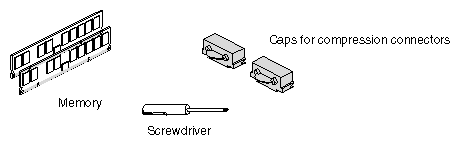
For this portion of the Duo installation, collect the following parts:
 | Note: The wrist strap you attached in Chapter 1 should remain in place until all tasks are complete. |
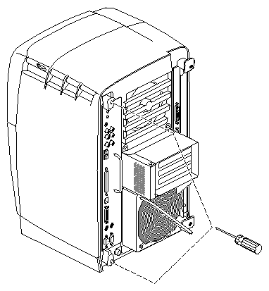

Warning: The heat sinks on the CPU and system module become very hot. Wait five minutes after powering off the OCTANE workstation before you remove the system module. Test before touching the CPU or heat sinks.
Loosen the captive screws that hold the sliding handles to the OCTANE workstation. See Figure 3-2.
For illustration purposes, the optional PCI module is shown installed.
Compression connectors are very delicate. Before you remove the system module, be aware that these connectors are on the side opposite the handles. This section tells you about them so that you are aware of their location and delicacy before you remove the system module.

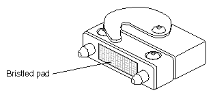
Caution: The gold bristled pad on the compression connectors on the back of the system module is very delicate and easily damaged. Before you remove the system module, read Appendix B, “Care and Cleaning of the Compression Connectors.”
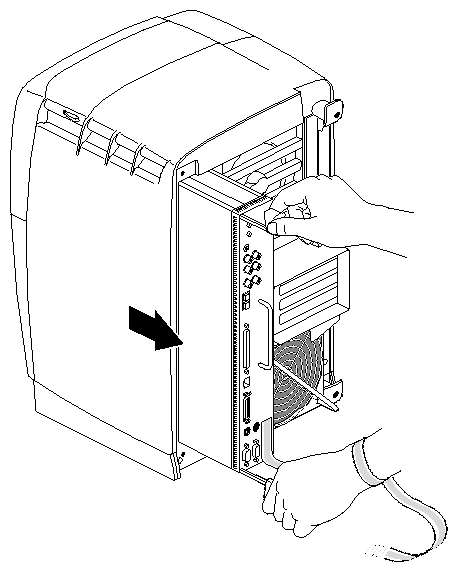
Pull both sliding handles simultaneously until they are completely extended. This action releases the system module from the workstation.
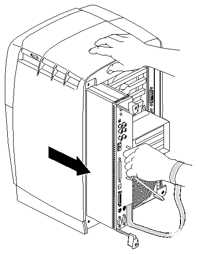
Pull the system module from the chassis by grasping the module handle with your left hand and bracing your right hand against the top of the workstation.
Support the bottom of the module as you pull it out.
Place it on a dry, antistatic surface with the CPU and DIMMs facing up. Your desktop works well.
Caution: Do not touch the compression connectors as you remove the system module. The side of the compression connector that connects to the workstation is extremely delicate. See Appendix B for information and care of the compression connectors.
Place a cap on each compression connector on the back of the system module.
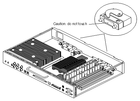
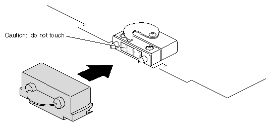
Warning: The heat sinks on the CPU and system module become very hot. Wait five minutes after powering off the workstation before touching them, and then test before touching them.
Before you install DIMMs in your OCTANE workstation, read the following information.
Bank 1 (sockets 1 and 2) must always be filled.
Minimum memory configuration is 64 MB in a bank (2 x 32 MB DIMM).
Maximum configuration is 512 MB in a bank (2 x 256 MB DIMM).
Banks are filled sequentially; when bank 1 is full, fill bank 2. Do not skip banks.
Each bank is either empty or contains two DIMMs, one in each of the two sockets.
Each banks of DIMMs must contain two DIMMs of the same capacity or density and of the same type.
Capacity refers to the number of megabytes in a DIMM: 32, 64, 128, and so on.
Type refers to the construction of the DIMM. Because DIMM construction cannot be determined visually, it is important to know that two DIMMs are the same type before you begin installation. If you insert two DIMMs of different types, the system will not work. Banked DIMMs and stacked DIMMs are two examples of many different types of memory.
SGI DIMMs have color-coded labels with a part number in the middle of the label:
The 32 MB DIMM has a yellow label.
The 64 MB stacked DIMM has a blue label.
The 64 MB DIMM (not stacked) has a green label.
The 128 MB DIMM has a brown label.
The 256 MB stacked DIMM has a red label.
Minimum memory capacity in the OCTANE workstation is 64 MB (2 x 32 MB DIMMs).
Maximum memory capacity in the OCTANE workstation is 2 GB (8 x 256 MB DIMMs).
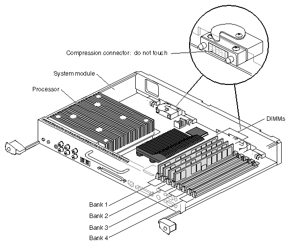
The DIMM banks are located on the system module, as shown in Figure 3-8.
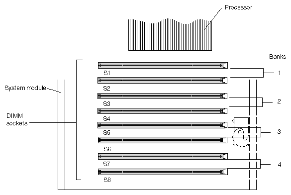
DIMM sockets are labeled between sockets, as shown in Figure 3-9.
| Caution: Dual inline memory modules (DIMMs) are extremely sensitive to static electricity. Handle the DIMMs carefully and wear the wrist strap to avoid conducting static electricity. |
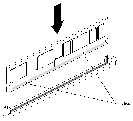
DIMMs are notched on the bottom so that they cannot be inserted incorrectly.
Insert the DIMM into the socket. Push firmly; you may need to use some force. You hear a click as it is seated, and the latch on the end of the socket moves up.
Install the second DIMM in its socket. DIMMs must be installed in pairs.
Check to be sure both sockets in the bank are full.
You have finished installing memory and are ready to replace the system module. Go to “Replacing the System Module”.
To remove memory, go to Chapter 1 and follow the instructions in that chapter. Then go to the beginning of this chapter, and follow the instructions for removing the system module.
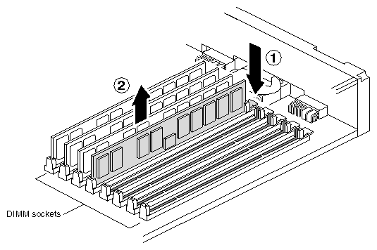
With the system module lying on a flat, dry, antistatic surface, locate the DIMM banks and sockets as shown in Figure 3-9 and Figure 3-8.
Locate the DIMMs you want to remove.
Caution: Do not touch the connector near the DIMM removal levers. Remove the DIMMs.
Press down on the latch at the end of the DIMM socket. The DIMM partially ejects from the socket.
Remove the DIMM.
Note: DIMMs must be in pairs of two (two in each bank) for the system to function. Either remove two DIMMs, or remove one and replace it. To install a new DIMM, see “Installing Memory”. To replace the system module, see “Replacing the System Module”.
When you are finished with your tasks in this chapter:
Remove the wrist strap.
Skip to Chapter 7, for instructions on replacing the cables and powering on the OCTANE workstation.

Remove the caps on the compression connectors on the back of the system module. Do not touch the system module compression connectors as you lift the module into the workstation.
Caution: To avoid damage to your OCTANE workstation, the power cord must be unplugged from the electrical socket before your insert the system module.
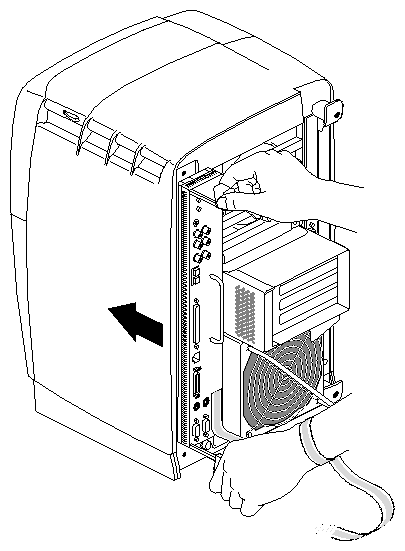
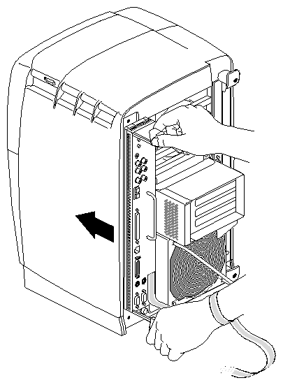
Grasp the system module by its stationary handle and support it with one hand as you slide it into the chassis.
Push the module firmly and completely into the chassis using the stationary handle. (Both sliding handles protrude.) The insertion requires some force.
The system module stops when it is slightly out of the chassis.The system module must be almost completely inserted before the hooks on the ends of the sliding handles can attach to the workstation and completely seat the compression connectors.
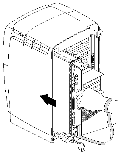
Push the sliding handles simultaneously to connect the system module to the workstation.
Push firmly on the handles to completely lock the system module to the workstation. (If the sliding handles won't lock, use the stationary handle to push the system module further toward the workstation. The hooks on the ends of the moveable handles must attach to the workstation for seating to be complete.)
When the system module is fully seated and locked to the worksation, the handles are completely recessed and the system module is flush wit the chassis.
Tighten the captive screws in the sliding handles.
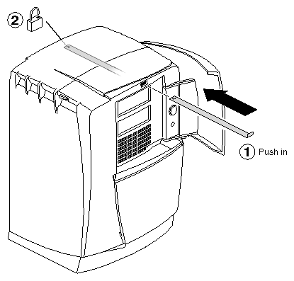
You have finished installing memory.
Go to Chapter 4 to begin your next task, installing the PCI board in the PCI module.