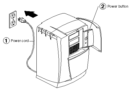
This chapter contains information on removing the PCI module and PCI boards.
The following topics are covered in this chapter:
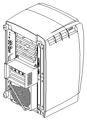
The PCI slots are located inside the PCI module, which protrudes from the rear of your OCTANE workstation. You remove the PCI module to install or remove PCI boards. Follow the instructions in this chapter to power off the workstation and remove the PCI module and PCI boards.
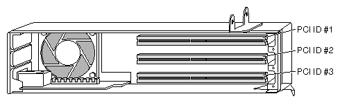
PCI physical slots and slots identified in software have the same designation:
The top slot is PCI ID #1.
The middle slot is PCI ID #2.
The bottom (half-sized) slot is PCI ID #3.
Before you begin your task, power off the OCTANE workstation.
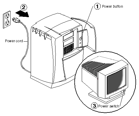
Open the cover and push the power button to power off the OCTANE workstation.
Unplug the power cord from the electrical outlet.
Press the monitor power switch to turn off the monitor.
Face the rear of the workstation.
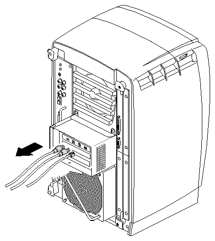
Remove any cables from the PCI module.
The components inside the OCTANE workstation are extremely sensitive to static electricity; you must wear the wrist strap while replacing parts.
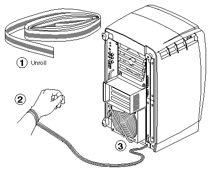
Unroll the first two folds of the band and wrap the exposed adhesive side firmly around your wrist.
Unroll the rest of the band and peel the liner from the copper foil at the opposite end.
Attach the copper foil to the PCI module, or use any convenient and exposed electrical ground, such as a metal part of the OCTANE workstation.
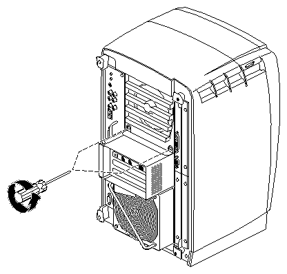
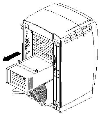
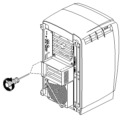
Loosen the two captive screws that secure the PCI module to the OCTANE workstation until they are disconnected from the chassis.
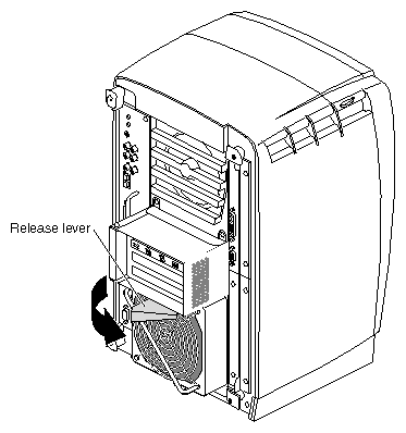
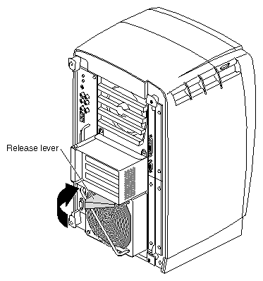
Pull the release lever toward you and to the right. You will feel resistance as you open the lever. Continue to pull until the lever is at the angle shown in Figure 5-7. The lever releases the locking mechanism that attaches the PCI module to the workstation.
Slide the PCI module from the chassis. Place it on a dry, antistatic surface such as your desktop.
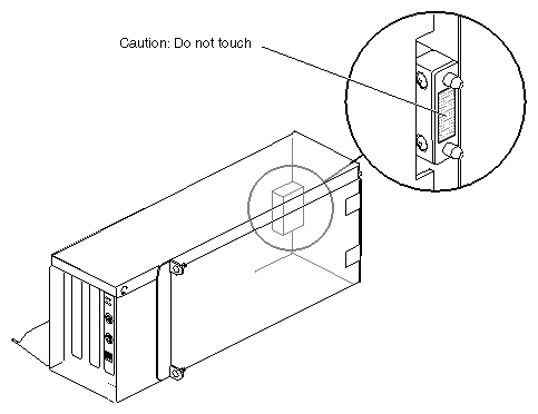
 | Caution: The compression connector on the back of the PCI module is delicate and easily damaged. Do not touch or bump the gold area of the compression connector. |
See Appendix B for information about and care of the compression connectors.
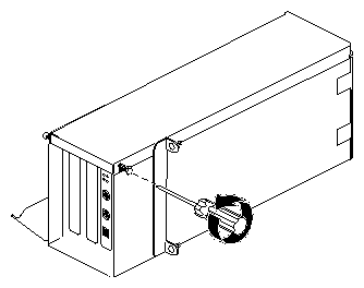
Turn the PCI module as shown in Figure 5-10.
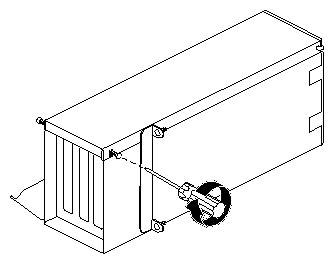
Loosen the screws holding the PCI module door closed, but do not remove them.
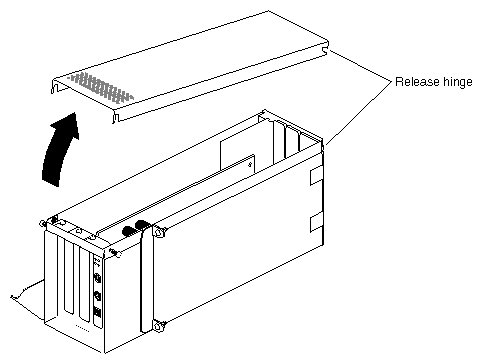
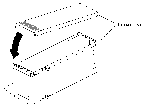
Pull up on the PCI module door. The release hinge allows the module door to slide up and off.
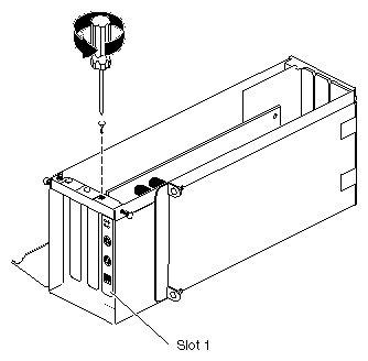
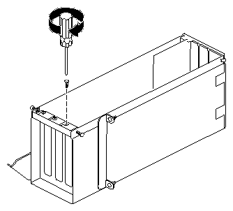
Remove the screw holding the PCI board to the module.
For illustration purposes, the PCI board is shown in slot 1.
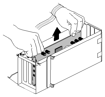
Grasp the PCI board on the top edge to extract it.
Pull up until the board releases. The board may be difficult to remove because it fits snugly into the connector in the PCI module
To install a PCI board, go to step 7.
To install a blank panel, go to “Installing a Blank Panel”.
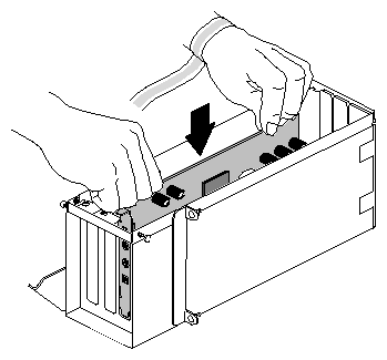
Insert the PCI board into the PCI module. Push gently but firmly until the PCI board snaps into place.

Note: Replace a new PCI Ethernet/keyboard/mouse board in the same slot from which you removed the old one. If you replace this board into a different slot, the system software remembers the first board, and thinks you have two similar boards installed. If you must place the board in a different slot, see Appendix D for instructions on deleting the ioconfig.conf file so that only one board is recognized. Skip to “Installing a Blank Panel,” step 2, on .
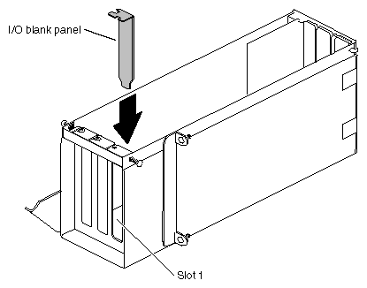
Install an I/O blank panel in the I/O door in place of the PCI board.
Be sure to place the tip of the I/O blank panel inside the groove at the bottom of the PCI module. Do not position the tip outside the groove.
Attach the blank panel (or new PCI board) to the I/O door with a screw. Replace and tighten any other screws that hold boards to the I/O door.
For illustration purposes, a blank panel, rather than a PCI board, is shown in the remaining steps of this chapter.
Fit the hinged door to the PCI module.
Tighten the door screws.

Remove the cap from the compression connector on the back of the PCI module, and save it for future use.
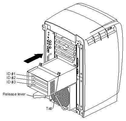
Note: If the release lever is not pulled out as shown in Figure 5-20, pull it out. It must be out for the PCI module to lock to the workstation. The release lever is attached to the bottom of the PCI module. Place the PCI module in the chassis and push it in until the tabs are flush with the chassis.
Close the release lever by pushing it to the left until it is parallel with the PCI module. You will feel some resistance as you close the lever.
Tighten the captive screws that hold the PCI module to the chassis.
| Note: If you plan to use the networking capability of the PCI board, you must configure this port. See Appendix D for configuration information and resources after you have completed all the tasks for setting up the Duo system. |
You have finished replacing the PCI module and are ready to power on the workstation.