This chapter describes how to remove and replace internal components of an Origin200 system.
Tools required to service parts inside the Origin200 server:
The following miscellaneous fasteners are used in the Origin200 server:
This section describes how to remove and install the following internal parts of the Origin200 server:
SCSI backplane
fans
system controller
Procedures to remove and replace the following components are described in other chapters in this guide:
Memory is described in Chapter 5, “Installing and Removing Memory.”
PCI boards are described in Chapter 6, “Installing and Removing PCI Option Boards.”
3.5-inch and 5.25-inch peripherals are described in Chapter 7, “Installing and Configuring Peripherals.”
The procedures in this step apply to all subsequent service instructions in this chapter, except for replacing the module system controller.
Follow these steps to prepare the Origin200 for servicing:
Shut down the system.
Turn off the main power switch.
Disconnect all of the cables that are attached to the rear of the system (power, CrayLink Interconnect, Ethernet, etc.).
Place the system on its side on a flat work surface.

Caution: Two people are required to lift and move the Origin200 server. If the system is mounted in an equipment rack, remove it according to the instructions in “Removing a Server From an Equipment Rack,” in Chapter 3, “Installing an Origin200 System in a Rack.”
If the system is in a tower configuration, you may wish to place a thin, soft pad (such as a cloth or piece of cardboard) under the top edge of the system to keep the top-cap from becoming marred or scratched.
Remove the chassis access cover, as shown in Figure 9-1.
Attach one end of a grounding strap to your wrist and the other to a metal portion of the Origin200 chassis.

Warning: Whenever you work on internal components, always use a grounding (wrist) strap to prevent the flow of potentially damaging static electricity.
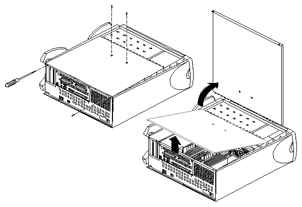
You are now finished preparing the system for servicing. Proceed with the next appropriate section, depending upon which component you are replacing.
If you have not done so already, follow the procedures in “Preparing the Origin200 for Servicing” to make sure the system is opened up and ready to work on.
Remove any 3.5-inch drives from the drive bays.
Detach the power cables from the SCSI backplane.
Note that the power cable plugs differ from each other. Figure 9-2 shows their locations.
If you are able, detach the SCSI cable from its connector; otherwise, wait until the backplane is partway out of the chassis.
Snap down the six spring clips on the SCSI backplane, as pointed out in Figure 9-2.
Grasping the SCSI backplane by the edges, tilt it out. The backplane hangs on two pins; pull the backplane up off the pins.
With the board partway out of the chassis, unhook the SCSI cable at the left side of
the SCSI backplane, if you have not already done so. Remove the backplane from the chassis and set it aside.

Follow these steps to install a new SCSI backplane:
Hang the new SCSI backplane over the guide pins on the sheet metal wall (the one towards the front of the chassis).
As you lower the board in place, gently press in at the bottom of the board.
Push the top of the SCSI backplane towards the sheet metal wall, being careful not to damage the LEDs as you guide them through their respective holes.
Reattach the cables.
Snap the six spring clips back up into place.
If you have not done so already, follow the procedures in “Preparing the Origin200 for Servicing” to make sure the system is opened up and ready to work on. Once you have opened the Origin200 chassis, follow these steps to remove a fan:
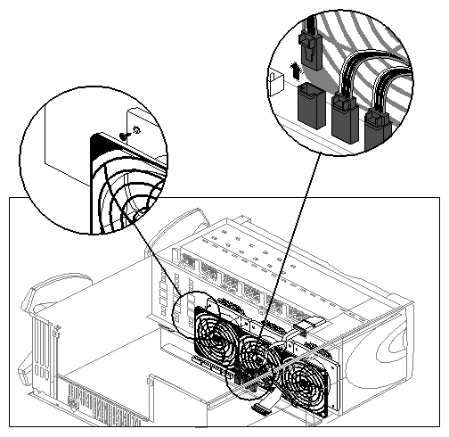
Unplug the power connector from the fan to the power supply, as shown in Figure 9-3.
Remove the two plastic rivets that hold the fan to the sheet metal, as shown in Figure 9-3. Push them out from behind the sheet metal with your fingertip.
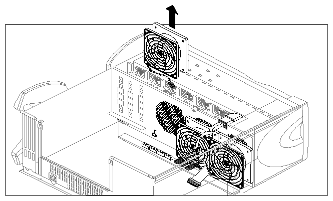
Lift the fan out of the system, as shown in Figure 9-4.
Follow these steps to install a fan:
Lower the new fan into the system.
Snap a plastic rivet in the top corners of the fan to secure it to the sheet metal.
The rivet has two parts: a sleeve and a pin.
Place the pin part-way inside the sleeve, then slide both through the hole in the fan.
Press the pin and sleeve together towards the sheet metal. The pin and sleeve will slide into place with the ends of both protruding through the sheet metal.
If you have large hands or fingers, you may find it easier to handle the rivets with needlenose pliers or large tweezers.
 | Note: For this procedure, you do not have to follow the instructions in “Preparing the Origin200 for Servicing.” The module system controller can be removed with the system in place and fully assembled. |
The module system controller (MSC) is mounted on a sheet metal carrier to form a single, assembly. This assembly is housed behind the plastic bezel crossbar that forms the system front panel (where the status LED is located).
Follow these steps to remove the MSC:
Power the system down and turn off the master power switch.
Open the front door.
-
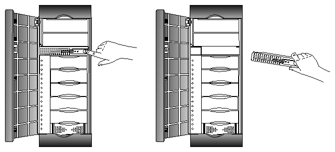
With your index finger, press against the catch on the inside of the recess in the crossbar, on the outside (right or top) of the recess. This recess is where the door lock fits. See Figure 9-5.
The crossbar swings out, hinging on the far side from the catch. Pull the crossbar out and set it aside.
Using a #2 Phillips screwdriver, remove the two screws that fasten the system controller assembly to the chassis, as shown in “Replacing the Module System Controller.”
Pull out the system controller assembly and lay it on a flat worksurface.
Warning: To prevent ESD damage to the module system controller, be careful not to touch the board's edge connectors (gold fingers). Remove the system controller board from its carrier; it is secured by a screw and
two pins, as shown in Figure 9-7.Remove the NIC (number in a can) package from the controller board. The NIC is a silver-colored device located at the rear of the controller board. It looks like a very large watch battery. See Figure 9-7.
The NIC stores the system serial number and should stay with your original Origin200 server.
Slide the NIC out of its socket and put it aside. You will install the NIC in the replacement module system controller.


Follow these steps to attach a new module system controller board to the sheet metal carrier and install it in the system:
Install the NIC from the original module system controller on the replacement controller board.
Position the replacement controller board over the pins; grasping the board by its sides, slide it so that the pins lock, making sure that the LED and button go through
the proper holes. Screw in the reserved screw, as shown in Figure 9-7.Remove the disks (or blanking plates if no disks are installed) from slots 5 and 6 of the Origin200 server. Removing the disks (or blanking plates) allows you to see how the edge connector on the module system controller board aligns with its socket inside the chassis.
Slide the system controller assembly into the chassis.
The assembly only installs in one direction.
If necessary, guide the edge connector into its socket.
When the edge connector is fully seated, the front of the carrier assembly should be flush with the chassis.
Warning: To prevent ESD damage to the module system controller, be careful not to touch the board's edge connectors (gold fingers). Replace the two Phillips screws that hold the carrier in place.
Replace the crossbar bezel.