This appendix describes the pinouts of the following external connectors on an Origin200 server:
serial ports
parallel port
Ethernet port
AUX (module system controller) port
For a description of cables that can be used with the serial and diagnostic ports, see Appendix B, “Cable Descriptions.”
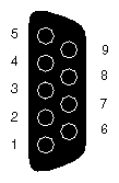
Table A-1 shows the connector pin assignments for the serial ports in RS-232 mode.
Table A-1. Origin200 Serial Port Pin Assignments, RS-232 Mode
Pin | Assignment |
|---|---|
1 | Data Carrier Detect (DCD) |
2 | Receive Data (RXD) |
3 | Transmit Data (TXD) |
4 | Data Terminal Ready (DTR) |
5 | Ground (GND) |
6 | Data Set Ready (DSR) |
7 | Request To Send (RTS) |
8 | Clear To Send (CTS) |
9 | (Not Connected) |
Table A-2 shows the connector pin assignments for the serial ports in RS-422 mode.
Table A-2. Origin200 Serial Port Pin Assignments, RS-422 Mode
Pin | Assignment |
|---|---|
1 | (Reserved) |
2 | Receive Data– (RXD–) |
3 | Transmit Data– (TXD–) |
4 | Transmit Data+ (TXD+) |
5 | Signal Ground (GND) |
6 | Receive Data+ (RXD+) |
7 | Output Handshake (HSKo) |
8 | Input Handshake (HSKi) |
9 | (Reserved) |

The Origin200 parallel port uses a 36-pin Centronics connector (IEEE 1284-C). Table A-3 shows the connector pinout assignments for the parallel port.
Table A-3. Origin200 Parallel Port Pin Assignments
Pin | Assignment |
|---|---|
1 | STB |
2 | DATA1 |
3 | DATA2 |
4 | DATA3 |
5 | DATA4 |
6 | DATA5 |
7 | DATA6 |
8 | DATA7 |
9 | DATA8 |
10 | ACK |
11 | BUSY |
12 | PE |
13 | ONLINE |
14 | PR/SC |
15 | NOPAPER |
16 | (Not Connected) |
17 | NOINK |
18 | (Not Connected) |
19–30 | Signal Ground (GND) |
31 | RESET |
32–36 | (Not Connected) |

Table A-4 shows the connector pinout assignments for the Ethernet 10-Base-T/100-Base-TX port.
Table A-4. Origin200 Ethernet 10-Base-T/100-Base-TX Port Pin Assignments
Pin | Assignment |
|---|---|
1 | Transmit + |
2 | Transmit – |
3 | Receive + |
4 | (Reserved) |
5 | (Reserved) |
6 | Receive – |
7 | (Reserved) |
8 | (Reserved) |

The AUX port is used to communicate with the module system controller (MSC). You can attach a serial (ASCII) terminal to the port, or attach a modem for remote access. Table A-5 shows the connector pin assignments for the port.
Table A-5. Origin200 AUX Port Pin Assignments
Pin | Assignment | Description |
|---|---|---|
1 | DTR | Data Terminal Ready |
2 | CTS | Clear to Send |
3 | TXD | Transmit Data |
4 | GND | Ground |
5 | RXD | Receive Data |
6 | RTS | Request to Send |
7 | DCD | Data Carrier Detect |
8 | GND | Ground |
 | Note: These pin assignments are the same as the ones for the serial ports on the Silicon Graphics Indy and Indigo2 workstations and the CHALLENGE S server. Cables that are appropriate for the serial ports of those machines can be used with the AUX port as well. |