This chapter describes how to use environmental, atmospheric, lighting, and other visual effects to enhance the realism of your application.
A pfEarthSky is a special set of functions that clears a pfChannel's viewport efficiently and implements various atmospheric effects. A pfEarthSky is attached to a pfChannel with pfChanESky(). Several pfEarthSky definitions can be created, but only one can be in effect for any given channel at a time.
A pfEarthSky can be used to draw a sky and horizon, to draw sky, horizon, and ground, or just to clear the entire screen to a specific color and depth. The colors of the sky, horizon, and ground can be changed in real time to simulate a specific time of day. At the horizon boundary, the ground and sky share a common color, so that there is a smooth transition from sky to horizon color. The width of the horizon band can be defined in degrees.
A pfChannel's earth-sky model is automatically drawn by IRIS Performer before the scene is drawn unless the pfChannel has a draw callback set with pfChanTravFunc(). In this case it is the application's responsibility to clear the viewport. Within the callback pfClearChan() draws the channel's pfEarthSky.
Example 8-1 shows how to set up an pfEarthSky().
Example 8-1. How to Configure a pfEarthSky
The complexities of atmospheric effects on visibility are approximated within IRIS Performer using a multiple-layer sky model, set up as part of the pfEarthSky function. In this design, individual layers are used to represent the effects of ground fog, clear sky, and clouds. Figure 8-1 shows the identity and arrangement of these layers.
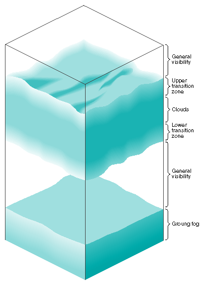
The lowest layer consists of ground fog, extending from the ground up to a user-selected altitude. The fog thins out with increasing altitude, disappearing entirely at the bottom of the general visibility layer. This layer extends from the top of the ground fog layer to the bottom of the cloud layer's lower transition zone, if such a zone exists. The transition zone provides a smooth transition between general visibility and the cloud layer. (If there is no cloud layer, then general visibility extends upward forever.) The cloud layer is defined as an opaque region of near-zero visibility; you can set its upper and lower boundaries. You can also place another transition zone above the cloud layer to make the clouds gradually thin out into clear air.
Set up the atmospheric simulation with the commands listed in Table 8-1
Table 8-1. pfEarthSky Routines
Function | Action |
|---|---|
Create a pfEarthSky | |
Set the render mode | |
Set the attributes of the earth and sky models | |
Set the colors for earth and sky and clear | |
Set the fog functions |
You can set any pfEarthSky attribute, mode, or color in real time. Selecting the active pfFog definition can also be done in real time. However, changing the parameters of a pfFog once they are set isn't advised when in multiprocessing mode.
The default characteristics of a pfEarthSky are listed in Table 8-2.
Table 8-2. pfEarthSky Attributes
Attribute | Default |
|---|---|
Clear method | |
Clear color | 0.0 0.0 0.0 |
Sky top color | 0.0 0.0 0.44 |
Sky bottom color | 0.0 0.4 0.7 |
Ground near color | 0.5 0.3 0.0 |
Ground far color | 0.4 0.2 0.0 |
Horizon color | 0.8 0.8 1.0 |
Ground fog | NULL (no fog) |
General visibility | NULL (no fog) |
Cloud top | 20000.0 |
Cloud bottom | 20000.0 |
Cloud bottom color | 0.8 0.8 0.8 |
Cloud top color | 0.8 0.8 0.8 |
Transition zone bottom | 15000.0 |
Transition zone top | 25000.0 |
Ground height | 0 |
Horizon angle | 10 degrees |
By default, an earth-sky model isn't drawn. Instead, the channel is simply cleared to black and the Z-buffer is set to its maximum value. This default action also disables all other atmospheric attributes. To enable atmospheric effects, select PFES_SKY, PFES_SKY_GRND, or PFES_SKY_CLEAR when turning on the earth-sky model.
Clouds are disabled when the cloud top is less than or equal to the cloud bottom. Cloud transition zones are disabled when clouds are disabled.
Fog is enabled when either the general or ground fog is set to a valid pfFog. If ground fog isn't enabled, no ground fog layer will be present and fog will be used to support general visibility. Setting a fog attribute to NULL disables it. See “Fog” for further information on fog parameters and operation.
The earth-sky model is an attribute of the channel and thus accesses information about the viewer's position, current field of view, and other pertinent information directly from pfChannel. To set the pfEarthSky in a channel, use pfChanESky().
 | Note: Note: |
pfLightPoint nodes have been obsoleted in favor of the libpr attribute, pfLPointState described in “pfLPointState”. However, the pfLightPoint node is still available for convenience.
A pfLightPoint is a pfNode that contains one or more light points. Light points are used in flight simulation applications to simulate runway lighting, taxiway lights, and street lights. The light points in a pfLightPoint node share all attributes except point location. A pfLightPoint node can be thought of as representing a string of similar point lights.
pfNewLPoint() creates and returns a handle to a pfLightPoint node. pfLPointSize() sets the screen size for all points in a pfLightPoint. The size is specified in pixels and is used as the argument to the IRIS GL function pntsizef() or the OpenGL function glPointSize().
Whenever possible, graphics library antialiased points are used to represent light points, but the actual representation depends on the graphics hardware being used. See the IRIS GL pntsizef() reference page or the OpenGL glPointSize() reference page for a description of available light point sizes on your IRIS hardware.
pfLPointColor() sets the color for a specified light point in the given pfLightPoint node. Each light in a pfLightPoint can be turned off by setting its red, green, and blue values to 0.0, or by setting its alpha value to 0.0 (which makes it completely transparent). Light points with a color of zero will not be considered for rendering.
pfLPointRot() and pfLPointShape() control the direction and shape of all the lights points in a pfLightPoint. The direction of the light points in lpoint is the positive Y axis, rotated about the X axis by elev and then rotated about the Z axis by azim. Roll affects only the light envelope. pfLPointShape() is used to set the intensity distribution of the light points (their visibility envelope). A pfLightPoint can have any one of three envelope shapes: omnidirectional, unidirectional, or bidirectional. If a light point is omnidirectional, it can be seen from any direction with the same intensity. This is the fastest light to process and draw using IRIS Performer.
Unidirectional and bidirectional lights have an elliptical cone of intensity. The intensity falloff from the center of the cone to the edge is exponential and is also set with pfLPointShape().
pfLPointPos() is used to set the position of each light point in a pfLightPoint. A runway strobe could be implemented with a pfLightPoint containing a single point and repositioning that point at regular intervals. A rotating beacon could be created using a single point and rotating it each frame using pfLPointRot().
A pfLPointState is a libpr attribute which, when attached to an appropriately configured pfGeoState will cause pfGeoSets of type PFGS_POINTS to be rendered as light points. pfLPointStates are intended to obsolete pfLightPoints since they provide a more powerful mechanism for simulating light points. Special features of the pfLPointState include:
Perspective point size -- points farther away look smaller than those closer to the eye.
Perspective fading -- points whose computed size is less than an application-defined threshold are made more transparent, rather than shrinking the point any further.
Fog punch-through.
Directionality including bi-directional points with different front and back colors.
Since pfLPointState uses the pfGeoState mechanism, light points can appear different to different pfChannels by using indexed pfGeoStates and pfGeoState tables. For example, a light point may look brighter in an infra-red channel than in an out-the-window channel.
One improvement over pfLightPoints is that point directions are supplied by a pfGeoSet's normals so a single pfLPointState can be used for many light points with differing directions. A further improvement is in performance. pfLPointStates can use texture mapping to simulate either directionality or both perspective fading and fog punch-through. This frees the CPU from making these expensive calculations. Example 8-2 is a portion of the sample program, lpstate.c found in /usr/share/Performer/src/pguide/libpf/C.
Example 8-2. How to set up a pfLPointState
#define NPOINTS2 30
#define NPOINTS (NPOINTS2 * (NPOINTS2 - 2))

static pfGeode*
initLPoints(void)
{
 pfLPointState    *lps;
 pfTexGen *tgen;
 pfTexture *tex;
 pfGeoState *gst;
 pfGeode *gd;
 pfGeoSet *gs;
 pfVec3     *norms, *colors, *coords;
 pfMatrix        squash, squashInvTransp;
 float     phi, dphi, theta, dtheta;
 int i, j, k;
 void        *arena = pfGetSharedArena();

 /*---- Set up pfLPointState ----*/

 lps = pfNewLPState(arena);

 /* Enable perspective size computation */
 pfLPStateMode(lps, PFLPS_SIZE_MODE, PF_ON);

 /* Clamp point size between .25 and 4 pixels */
 pfLPStateVal(lps, PFLPS_SIZE_MIN_PIXEL, .25f);
 pfLPStateVal(lps, PFLPS_SIZE_MAX_PIXEL, 4.0f);

 /* Real-world point size is .15 meters */
 pfLPStateVal(lps, PFLPS_SIZE_ACTUAL, .15f);

 /* Fade points smaller than 2 pixels */
 pfLPStateVal(lps, PFLPS_TRANSP_PIXEL_SIZE, 2.0f);

 /* Linear fade, scaled by .6 and alpha clamped at .1 */
 pfLPStateVal(lps, PFLPS_TRANSP_EXPONENT, 1.0f);
 pfLPStateVal(lps, PFLPS_TRANSP_SCALE, .6f);
 pfLPStateVal(lps, PFLPS_TRANSP_CLAMP, .1f);

 /* Points are fogged as if 4 times closer than they really are */
 pfLPStateVal(lps, PFLPS_FOG_SCALE, .25f);

 /* Compute true, slant range from eye to points */
 pfLPStateMode(lps, PFLPS_RANGE_MODE, PFLPS_RANGE_MODE_TRUE);

 /* Points are bidirectional with purple back color */
 pfLPStateMode(lps, PFLPS_SHAPE_MODE,                     PFLPS_SHAPE_MODE_BI_COLOR);
 pfLPStateBackColor(lps, 1.f, 0.0f, 1.f, 1.0f);

 /*
 * Point shape is 15 horiz and 60 degrees vertical with
 * no roll, falloff of 1 and ambient intensity of .1
 */
 pfLPStateShape(lps, 15.0f, 60.0f, 0.0f, 1, .1f);

 /*---- Set up pfGeoState ----*/

 gst = pfNewGState(arena);

 /* Specify high-quality transparency */
 pfGStateMode(gst, PFSTATE_TRANSPARENCY,
         PFTR_BLEND_ALPHA | PFTR_NO_OCCLUDE);
 pfGStateVal(gst, PFSTATE_ALPHAREF, 0.0f);
 pfGStateMode(gst, PFSTATE_ALPHAFUNC, PFAF_GREATER);

 pfGStateMode(gst, PFSTATE_ENFOG, 0);
 pfGStateMode(gst, PFSTATE_ENLIGHTING, 0);
 pfGStateMode(gst, PFSTATE_ENTEXTURE, 1);
 pfGStateMode(gst, PFSTATE_ENLPOINTSTATE, 1);
 pfGStateAttr(gst, PFSTATE_LPOINTSTATE, lps);

 /*---- Configure texturing ----*/

 tgen = pfNewTGen(arena);
 tex = pfNewTex(arena);

#define USE_TEXTURE_MAPPING_FOR_DIRECTIONALITY
#ifdef USE_TEXTURE_MAPPING_FOR_DIRECTIONALITY
 /*
 * Use texture mapping for directionality. CPU computes size
 * and range and fog attenuation
 */
 pfLPStateMode(lps, PFLPS_DIR_MODE, PFLPS_DIR_MODE_TEX);
 pfLPStateMode(lps, PFLPS_TRANSP_MODE,                     PFLPS_TRANSP_MODE_ALPHA);
 pfLPStateMode(lps, PFLPS_FOG_MODE, PFLPS_FOG_MODE_ALPHA);
 pfuMakeLPStateShapeTex(lps, tex, 256);
 pfGStateAttr(gst, PFSTATE_TEXTURE, tex);
 pfTGenMode(tgen, PF_S, PFTG_SPHERE_MAP);
 pfTGenMode(tgen, PF_T, PFTG_SPHERE_MAP);
#else
 /*
 * Use texture mapping for range and fog attenuation. CPU
 * computes size and directionality.
 */
 pfLPStateMode(lps, PFLPS_DIR_MODE, PFLPS_DIR_MODE_ALPHA);
 pfLPStateMode(lps, PFLPS_TRANSP_MODE,                     PFLPS_TRANSP_MODE_TEX);
 pfLPStateMode(lps, PFLPS_FOG_MODE, PFLPS_FOG_MODE_TEX);
 pfuMakeLPStateRangeTex(lps, tex, 256, pfNewFog(NULL));
 pfGStateAttr(gst, PFSTATE_TEXTURE, tex);
 pfTGenPlane(tgen, PF_S, 0.0f, 0.0f, 1.0f, 0.0f);
 pfTGenPlane(tgen, PF_T, 0.0f, 0.0f, 1.0f, 0.0f);
 pfTGenMode(tgen, PF_S, PFTG_EYE_PLANE_IDENT);
 pfTGenMode(tgen, PF_T, PFTG_EYE_PLANE_IDENT);
#endif
 pfGStateAttr(gst, PFSTATE_TEXGEN, tgen);
 pfGStateMode(gst, PFSTATE_ENTEXGEN, 1);

 /* Make PFGS_POINTS pfGeoSet arranged in a sphere */

 gd = pfNewGeode();
 gs = pfNewGSet(arena);
 pfGSetPrimType(gs, PFGS_POINTS);
 pfGSetNumPrims(gs, NPOINTS);

 colors = pfMalloc(sizeof(pfVec3) * NPOINTS, arena);
 coords = pfMalloc(sizeof(pfVec3) * NPOINTS, arena);
 norms = pfMalloc(sizeof(pfVec3) * NPOINTS, arena);
 pfGSetAttr(gs, PFGS_NORMAL3, PFGS_PER_VERTEX, norms, NULL);
 pfGSetAttr(gs, PFGS_COLOR4, PFGS_PER_VERTEX, colors, NULL);
 pfGSetAttr(gs, PFGS_COORD3, PFGS_PER_VERTEX, coords, NULL);

 pfGSetGState(gs, gst);
 pfAddGSet(gd, gs);

 /* Squash sphere into an ellipse so perspective point size
    is more easily seen
 */
 pfMakeRotMat(squash, 90.0f, 1.0f, 0.0f, 0.0f);
 pfPostScaleMat(squash, squash, 1.0f, 2.0f, .5f);
 pfInvertAffMat(squashInvTransp, squash);
 pfTransposeMat(squashInvTransp, squashInvTransp);

 dphi = 180.0f / (NPOINTS2-1);
 dtheta = 360.0f / NPOINTS2;

 phi = dphi;
 for (k=0, i=0; i<NPOINTS2 - 2; i++)
 {
    float    ct, st, sp, cp;

    theta = 0.0f;
    pfSinCos(phi, &sp, &cp);

    for (j=0; j<NPOINTS2; j++, k++)
    {
         pfSetVec4(colors[k], 1.0f, 1.0f, 1.0f, 1.0f);

         pfSinCos(theta, &st, &ct);
         pfSetVec3(norms[k], ct * sp, st * sp, cp);
         pfScaleVec3(coords[k], 10.0f, norms[k]);

         pfXformPt3(coords[k], coords[k], squash);
         pfXformVec3(norms[k], norms[k], squashInvTransp);
         pfNormalizeVec3(norms[k]);

         theta += dtheta;
     }

     phi += dphi;
 }
 return gd;
}
|
A pfLightSource node's primary purpose is to represent a graphics library light source (pfLight) in a scene graph. The position and orientation of the light source is affected by transformations inherited through the scene graph providing a simple means of moving lights about. In conjunction with an object's material properties (pfMaterial) and the global lighting model (pfLightModel), illumination is computed at geometry vertices by the Geometry Pipeline.
While this kind of “bread-and-butter” lighting is very efficient it does not adequately simulate certain important lighting effects. In particular, per-pixel spotlights and shadows are not supported by the default lighting mechanism. On graphics library implementations which support texture mapping, the pfLightSource node supports per-pixel spotlights and opera lighting through a technique called projective texturing and also support shadows if shadow map hardware is available. In practice, default lighting is used in conjunction with projected texturing since the latter does not consider geometry normals but the former does.
Both projected texturing and shadows require a pfFrustum which defines the “viewing volume” of the light source. The frustum's eye point is located at the pfLightSource position and the frustum's view direction is aligned along the pfLightSource's +Y axis. You can think of the frustum as a slide projector whose eyepoint is the projector's bulb and whose view plane is the slide holder and the projected texture map is the slide. A pfLightSource's frustum is set with pfLSourceAttr() with the PFLS_PROJ_FRUSTUM identifying token.
In addition to a frustum, projected texturing requires a texture map supplied with pfLSourceAttr() with PFLS_PROJ_TEX identifying token. This texture map can be anything but is usually a texture with identical intensity and alpha components which represent the soft-edged circle of a spotlight. Colored spotlights are simulated by coloring the pfLightSource with pfLSourceColor() rather than coloring the texture map. Opera lighting, where an actual color slide is projected onto the set, is simulated with a texture map consisting of red, green, blue, and alpha components (this is supported only if the pfLightSource is the only one that is projecting a texture).
Shadows do not require the application to supply a texture map; rather, one is automatically created by IRIS Performer. However, the size of the shadow map has an important effect on the quality of the shadows and may be set with the PFLS_SHADOW_SIZE token to pfLSourceVal(). For high quality shadows, the pfLightSource's frustum must encompass the entire scene that is to be shadowed as tightly as possible. If the frustum's field-of-view or far to near clipping plane ratio becomes too large, the shadows will become blocky and incorrect. One way to improve shadow quality is to increase the size of the shadow map but this will decrease performance.
Projected textures and shadows both use texture mapping so if your scene is texture mapped, multiple rendering passes are required to combine the projected texture with the normal scene textures. In pfDraw(), pfChannels assume the scene is textured and automatically render the scene multiple times. However, if your scene is not textured you can avoid a complete rendering pass by setting the PFMPASS_NONTEX_SCENE bit in the PFTRAV_MULTIPASS mode given to pfChanTravMode().
Example 8-3 is a code snippet which shows how to set up both projected texture and shadowing pfLightSources.
Example 8-3. Projected texture and shadow pfLightSources
pfFrustum *shadFrust; pfLightSource *shad, *proj; pfDCS *shadDCS, *projDCS; pfTexture *tex; // Create and configure shadow frustum shadFrust = pfNewFrust(arena); pfMakeSimpleFrust(shadFrust, 60.0f); pfFrustNearFar(shadFrust, 1.0f, 100.0f); /* Create and configure red shadow casting light source */ shad = pfNewLSource(); pfLSourceMode(shad, PFLS_SHADOW_ENABLE, 1); pfLSourceAttr(shad, PFLS_PROJ_FRUST, shadFrust); pfLSourceColor(shad, PFLT_DIFFUSE, 1.0f, 0.0f, 0.0f); pfLSourceVal(shad, PFLS_INTENSITY, .5f); pfLSourcePos(shad, 0.0f, 0.0f, 0.0f, 1.0f); /* make local */ /* Create and configure blue spotlight */ proj = pfNewLSource(); tex = pfNewTex(arena); pfLoadTexFile(tex, “spotlight.inta”); pfLSourceMode(proj, PFLS_PROJTEX_ENABLE, 1); pfLSourceAttr(proj, PFLS_PROJ_FRUST, shadFrust); pfLSourceAttr(proj, PFLS_PROJ_TEX, tex); pfLSourceColor(proj, PFLT_DIFFUSE, 0.0f, 0.0f, 1.0f); pfLSourceVal(proj, PFLS_INTENSITY, .5f); pfLSourcePos(proj, 0.0f, 0.0f, 0.0f, 1.0f); /* make local */ /* Add to DCSes so we can move lights around */ shadDCS = pfNewDCS(); pfAddChild(shadDCS, shad); pfAddChild(scene, shadDCS); projDCS = pfNewDCS(); pfAddChild(projDCS, proj); pfAddChild(scene, projDCS); |
For scenes with multiple pfLightSources you can scale the contribution from each source with the PFLS_INTENSITY value so that the total illumination from all sources does not exceed one. Otherwise lighted geometry may become saturated and not look real.
pfLightSources which are located near the eyepoint and which project a texture to simulate spotlights can attenuate the spotlight based on range by using a pfFog to define the falloff ramp. The pfFog is set with the PFLS_PROJ_FOG token to pfLSourceAttr() and should have the same color as the lighting ambient.
Morphing is the smooth transition from one particular appearance to another. Morphing can refer to images or geometry colors, texture coordinate or coordinates. For example, you could “morph” the following:
the image of a person's face into that of another person
color to simulate a flickering fire
texture coordinates to simulate rippling ocean waves
coordinates to make a 3D model of a face smile or frown.
pfMorph is a group node that supports the morphing of lists of numbers. These numbers could be colors, coordinates, or pixels -- it is up to you to decide what to morph.
Conceptually, pfMorph combines multiple input lists of numbers into a single output list. This output may be used arbitrarily but is most often used as a pfGeoSet attribute array, be it colors, normals, texture coordinates, or coordinates. The combination is linear, that is, the input lists are scaled by a value (which has no restricted range) and then summed together to produce the output. One example of geometric morphing is in facial animation where multiple input faces with canonical expressions: smiley, frowny, surprised, are combined to produce a face with a mixture of expressions.
pfMorphs can handle multiple sets of input->output lists so a single pfMorph could, for example, morph the normals and coordinates of an animated figure. An input->output set is called a morph attribute since a set typically corresponds to a pfGeoSet attribute. Morph attributes are specified with pfMorphAttr(). Example 8-4 is a snippet of the morph.c test program in /usr/share/Performer/src/pguide/libpf/C/ shows how to configure a pfMorph node that morphs the normals and coordinates of a pfGeoSet.
Example 8-4. How to set up a pfMorph node.
/* Sinusoidally modify morph weights to oscillate between
* cube and sphere.
*/
static void
breatheMorph(pfMorph *morph, double t)
{
 float     s = (sinf(t) + 1.0f) / 2.0f;
 float     weights[2];

 weights[0] = s;
 weights[1] = 1.0f - s;

 pfMorphWeights(morph, 0, weights); /* coordinate weights*/
 pfMorphWeights(morph, 1, weights); /* normal weights */
}


static pfMorph*
initMorph(void)
{
 pfGeoSet     *gset;
 pfGeode     *geode;
 pfGeoState     *gstate;
 pfMaterial     *mtl;
 pfMorph     *morph;
 ushort     *icoords, *inorms;
 pfVec3     *coords, *ncoords, *norms, *nnorms;
 float     *srcs[2];
 int          i, nSph;
 void     *arena = pfGetSharedArena();

 morph = pfNewMorph();
 geode = pfNewGeode();
 gset = pfdNewSphere(400, arena);
 gstate = pfNewGState(arena);

 mtl = pfNewMtl(arena);
 pfMtlColor(mtl, PFMTL_DIFFUSE, 1.0f, 0.0f, 0.0f);
 pfMtlColor(mtl, PFMTL_SPECULAR, 1.0f, 1.0f, 1.0f);
 pfMtlColorMode(mtl, PFMTL_BOTH, PFMTL_CMODE_OFF);
 pfMtlShininess(mtl, 32);

 pfGStateAttr(gstate, PFSTATE_FRONTMTL, mtl);
 pfGStateMode(gstate, PFSTATE_ENLIGHTING, 1);
 pfGSetGState(gset, gstate);

 pfAddGSet(geode, gset);
 pfAddChild(morph, geode);

 /*
 * NULL forces recomputation of bound. Force it to be static
 * to avoid expensive recomputation. Static bound should
 * encompass the extent of all morph possibilities.
 */
 pfGSetBBox(gset, NULL, PFBOUND_STATIC);
 pfNodeBSphere(geode, NULL, PFBOUND_STATIC);

 pfGetGSetAttrLists(gset, PFGS_COORD3, (void**)&coords, &icoords);
 pfGetGSetAttrLists(gset, PFGS_NORMAL3, (void**)&norms, &inorms);
 nSph = pfGetSize(coords) / sizeof(pfVec3);

 ncoords = pfMalloc(pfGetSize(coords), arena);
 nnorms = pfMalloc(pfGetSize(norms), arena);

 for (i=0; i<nSph; i++)
 {
     int     max;
     float     t;

     /* Find which face of the cube this vertex maps to */
     if (PF_ABS(coords[i][PF_X]) > PF_ABS(coords[i][PF_Y]))
     {
      if (PF_ABS(coords[i][PF_X]) > PF_ABS(coords[i][PF_Z]))
          max = PF_X;
      else
          max = PF_Z;
     }
     else
     {
      if (PF_ABS(coords[i][PF_Y]) > PF_ABS(coords[i][PF_Z]))
          max = PF_Y;
      else
          max = PF_Z;
     }

     /* Compute cube normals and coordinates */
     pfSetVec3(nnorms[i], 0.0f, 0.0f, 0.0f);
     if (coords[i][max] < 0.0f)
     {
      t = -1.0f / coords[i][max];
      pfScaleVec3(ncoords[i], t, coords[i]);
      nnorms[i][max] = -1.0f;
     }
     else
     {
      t = 1.0f / coords[i][max];
      pfScaleVec3(ncoords[i], t, coords[i]);
      nnorms[i][max] = 1.0f;
     }
 }

 /* Morph attribute 0 is coordinates */
 srcs[0] = (float*)coords;
 srcs[1] = (float*)ncoords;
 pfMorphAttr(morph, 0, 3, nSph, NULL, 2, srcs, NULL, NULL);

 pfGSetAttr(gset, PFGS_COORD3, PFGS_PER_VERTEX,
      (void*)pfGetMorphDst(morph, 0), icoords);

 /* Morph attribute 1 is normals */
 srcs[0] = (float*)norms;
 srcs[1] = (float*)nnorms;
 pfMorphAttr(morph, 1, 3, nSph, NULL, 2, srcs, NULL, NULL);

 pfGSetAttr(gset, PFGS_NORMAL3, PFGS_PER_VERTEX,
      (void*)pfGetMorphDst(morph, 1), inorms);

 return morph;
}
|