This chapter describes what to do when your FDDI network connection has problems. The chapter describes the following topics:
When you experience difficulty with the FDDI network connection at a particular station, you can:
Check the physical connections at the station as detailed in “Checking Physical Connections.”
Search or read the /var/adm/SYSLOG file and console window for error messages. If you find any FDDI driver or SMT messages, read about them in Appendix A.
Use the SMT commands (or FDDIVisualyzer) to identify problematic status indicators, and if you find any, read about them in “Status Indicators and Symptoms”.
The following sections will help you with each of these suggested steps.
Check each of the following, using the step-by-step instructions:
Complete inability to access the FDDI ring may indicate that the board and software are not communicating. Follow the instructions below to figure out why.
In a shell window, type this command:
% /sbin/hinv
When a board is listed by hinv,, this does not mean that the board and driver are functional; it means that the operating system was able to recognize the board. For an explanation of the hinv screen display, see “Verifying the FDDI Connection” or the hinv(1M) man page.
If hinv displays an entry for the FDDI hardware, the operating system is recognizing the board. The problem may be bad cable connections or improperly configured software. First, follow one of the sets of instructions below, then (if necessary) follow the instructions in “Check Cables and Connectors.”
If hinv does not display an entry for the FDDI hardware, the operating system did not find the FDDI board the last time the station was booted. The problem may be an incompatible operating system, or a loose or dysfunctional board. First, follow the instructions below to verify the board, then follow the instructions in “FDDI Connection Has Not Been Functional Since Last Boot”.
Verify that the LEDs on the FDDI board indicate that the board is receiving power. If the LEDs indicate that there is no power to the FDDI board or that the board is not operational, follow the instructions in the board's hardware manual to troubleshoot the problem. It is possible that the board is not seated firmly into its connection to the system, or that the board is dysfunctional.
If you reinstall the board, take extra precautions to seat the FDDI board firmly.
If the FDDI connection has not been working since the last time the station was booted or if this is an initial installation of an FDDI product, one or more of the following could be occurring:
The operating system installed on the station is not compatible with the FDDI board installed.
The operating system has not been rebuilt to include the driver for the board.
The network interface for the board has not been configured properly.
Follow the instructions below to determine the cause of the problem:
Verify that the installed IRIX operating system (oeo1) and FDDIXPress software are the correct versions by doing the following:
Determine the correct versions. The FDDIXPress release notes indicate the correct IRIX and FDDIXPress versions for your FDDI board.
Use the versions command (shown below) to display the installed release identifications (versions). If the version is not correct, install the correct version. Then invoke hinv.
% /usr/sbin/versions eoe1
eoe1 date Execution Only Environment 1, version
% /usr/sbin/versions FDDIXPress
FDDIXPress date FDDIXPress release Option
Use the netstat command, as shown below, to display the currently configured network interfaces. If the FDDI interface is not displayed, continue to the next step. If the interface is displayed, but the configuration is incorrect, follow the instructions in “Configure the Station's Network Interfaces” to reconfigure it.
% /usr/etc/netstat -ina
Verify the FDDI entries in the /etc/config/netif.options file. For example, the network interface may be misspelled.
Use /etc/autoconfig to rebuild the operating system to include the FDDIXPress driver. Then, reboot the system to start using the new operating system. Finally, invoke netstat -ina again. If the FDDI interface is still missing, contact the Silicon Graphics Technical Assistance Center.
If new software (operating system, FDDIXPress, or another network communications software) has been installed since the FDDI connection was last functional, the problem is probably incompatible software. Verify that the software you last installed supports the FDDI board installed in the station.
If the FDDI connection has been functional after the last new software was installed, the problem is probably the board. The board may have become loosened from its connection to the system or it may be dysfunctional.
Follow these steps to resolve the problem:
Verify that the LEDs on the FDDI board indicate that the board is receiving power. If the LEDs indicate that there is no power to the FDDI board or that the board is dysfunctional, follow the instructions in the board's hardware manual to troubleshoot the problem. Otherwise, continue.
Ensure that the system is using the operating system that was built most recently. Use the /etc/autoconfig command to rebuild the operating system, then reboot to start using it. During the reboot, begin step 3.
Watch the messages on the terminal during restart to verify that each network interface is configured correctly. The messages should look similar to these examples:
Configuring xpi0 as mickey
Configuring ec0 as gate-mickey
If the FDDI driver is not mentioned on the terminal during startup, there is a problem with the software. Continue to step 4.
If a startup terminal message indicates that the hardware is missing, as in the following example, start again at the beginning of “Recognition of Board by Software”.
xpi0: missing
Use the netstat command to display the currently configured network interfaces. If the interface is displayed, but the configuration is incorrect, follow the instructions in section “Configure the Station's Network Interfaces” to reconfigure it.
% /usr/etc/netstat -in
The /etc/config/netif.options file may have an incorrect entry (for example, a misspelled network interface); verify all file contents carefully.
If the FDDI interface does not display, it is possible the board or software is dysfunctional. Contact the Silicon Graphics Technical Assistance Center.
A wrap on an A or B port, a high level of link-layer errors, or a stagnant token count can indicate a faulty cable, a loose or damaged connection, or a dirty cable end. The problematic cable or connection can be found at or near the station where the error is occurring.
At each cable connection, along the entire length of the ring where there is a problem, verify two things:
Each connection is tight. Many connectors must snap or click together to be tight. (Remember to verify the connections at each station's I/O panel.)
Each connection is correct.
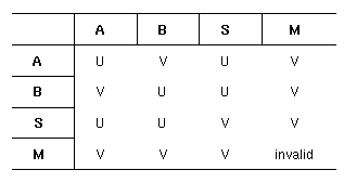
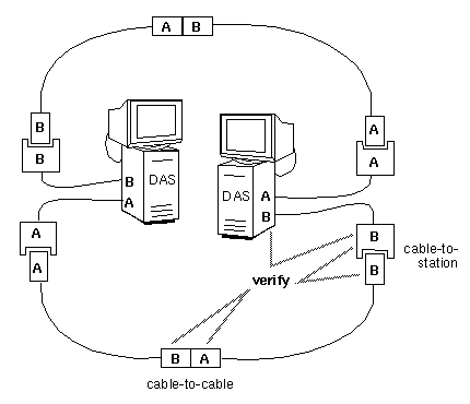
For cable-to-cable connections, the labels on the two cable connections must pair as a valid (V) connection, as summarized in Figure 4-1, where U indicates that the connection is undesirable, invalid indicates that it is invalid, and V indicates it is valid. Figure 4-2 illustrates valid connections for a typical ring.
For cable-to-station connections, the labels on the connectors must match (for example, A-to-A or red-to-red, not B-to-A or red-to-blue). (Remember to verify the connections at each station's I/O panel. The cable's label must match the port where it is connected.)
The ends of fiber optic cable can become dirty and interfere with the transmission of the optical signal. Common pollutants are oil (from being touched by human fingers) and dust (from being left uncapped).
 | Note: Do not touch the ends of fiber optic cable. Do not leave the fiber optic cable uncapped when it is not connected. The cap prevents dust and other pollutants from collecting on the exposed fiber optic material. |
Gently clean cable ends with 96% isopropyl alcohol and a non-lint producing soft material, or an alcohol-wipe product.
Fiber optic cable can become damaged if excessively bent (or coiled), twisted, or sharply struck. Replace suspect cables with functional cables.
When no replacement cable is available, use a small, powerful flashlight (as described in the bulleted steps below) to verify that the light signal passes through the cable. This test identifies broken or incorrectly built cables, but cannot identify borderline conditions.
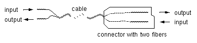
Identify the direction that light travels within each optical fiber line of the suspect cable. (FDDI MIC connectors and cable contain two optical fibers.)
Fiber optic material is designed somewhat like a funnel. Light travels in only one direction: from the wide end to the narrow end. Some cable manufacturers label each fiber with arrows. Some cables have connectors constructed so that the input end of each fiber is indicated by the connector's cover; the wider portion of the cover (the funnel's mouth) indicates the input end, as shown in Figure 4-3.
Shine the flashlight into one of the inputs. Verify that the light is visible and bright at the output end of that line. If the light is not visible or is dim, the cable is faulty. Replace it.
If the light is visible when shone in the opposite direction, the cable has been built improperly. Replace it.
Repeat step 2 for the other input line.
| Note: Special equipment is needed to accurately measure whether the optical signal is full strength. The flashlight test cannot tell if the signal is partially obstructed.Visible light at the other end of the cable does not guarantee that the cable is fully functional. |
An increasing bit-error rate may indicate that power is being lost because the cable is too long.
A typical manufacturer's maximum length of cable between DAS stations is 2 kilometers (approximately 1.24 miles) for regular fiber optic cable, but can be much longer (for example, 10 km) for newer low-loss fiber optic cable. Length is measured from the FDDI connector on the I/O panel of one station to the FDDI connection on the I/O panel of a neighbor station. This length is not the distance between the two stations; it is the length of the cable lying between two stations. Coils of cable lying in the closets, floors, or ceilings of buildings can quickly add up to this maximum, so beware.
A typical manufacturer's maximum length of cable allowed for one ring is 100 kilometers (approximately 62 miles). The total ring cable length is calculated by summing all the between-station lengths (as described in the paragraph above).
| Note: Special equipment is needed to measure the amount of power loss on a fiber optic cable. |
This section contains some common symptoms and smtstat status indicators accompanied by descriptions of what they may indicate and what you can do to remedy the problem.
A high rate of link-layer errors can indicate a cable problem very close to or on the local station. Follow the instructions for verifying and cleaning cable connections.
When the token count is not incrementing, the FDDI board is not seeing the light signals on the ring (neither port is functioning or there may be a problem with the ring).
This symptom may indicate that the FDDI network interface has been turned off. When this is the case, the Port Status report indicates that the MAC is OFF. Verify that the FDDI cables are connected, then use smtconfig to stop and restart the FDDI network interface.
If the problem persists, proceed to step 2.
Use the smtstat -s Port Status report to check the status of the receive line states.
If the report shows HLS, the problem is probably one of the neighbor stations or the ring. Verify that each neighbor station is functioning properly.
If the report indicates QLS, the problem is probably local to this station. The problem may be loose or damaged connectors, faulty cabling, or incorrectly connected ports. Follow the instructions in “Checking Physical Connections” for all cabling between the station's I/O panel and the ring.
Be especially careful to verify that the ends of the fiber optic cable at the I/O panel have not been damaged.
When claims or beacons increment rapidly for more than a few seconds, a station on the ring is malfunctioning or inserting itself. When the symptom persists for more than 5 minutes or is observed on three consecutive occasions (when you are certain no new stations are being added), follow these steps to locate the dysfunctional station, then remove it from the ring. This procedure can be very time consuming. A malfunctioning station is sometimes difficult to locate.
Locate a patch for the ring. The following items can be used to patch a ring: an optical bypass switch, a fiber optic barrel connector, or an extra length of your ring's fiber optic cabling with appropriate connectors.
Physically disconnect one station from the ring.
Insert the patch into the ring (to fill the gap where the station was).
Wait two or three minutes. During this time, the stations remaining on the ring rearrange themselves.
Go to another station. Check if the problem has been remedied.
If the problem no longer manifests, you know that all the remaining stations are functioning properly. Do not return the dysfunctional station to the ring until it has been fixed.
If the problem still exists, go to step 7.
Reinsert the disconnected station. Repeat steps 2–6.
When the ring is wrapped, follow these instructions:
At each dual ring DAS, use the smtstat -s Port Status report to verify that neither port's transmit line state is in WRAP.
The transmit lines for a two-port FDDI board that is connected to a concentrator normally indicate WRAP. This is normal and not a problem.
When you locate a WRAP, look at the Port Status report's flags to verify that the WRAP is not caused by an undesirable (CON_undesirable) or illegal connection (C_illegal). If you identify a problematic connection, follow the instructions in “Check Cables and Connectors” to remedy the problem. Otherwise, proceed to step 3.
When you locate two dual ring DASes, each with one of its ports in WRAP, you have identified the boundaries of the functioning and nonfunctioning sections of the ring. The fault can be found somewhere between the two stations: downstream from the station whose port A is wrapped and upstream from the station whose port B is wrapped.
Follow the instructions in “Checking Physical Connections” for the connectors and cables within the identified fault domain. If the problem persists, proceed to step 5.
Starting with either of the boundary stations, perform these steps to determine whether the fault is caused by the operating system or SMT module within one of the stations located along the fault domain.
Locate a patch for the ring. The following items can be used to patch a ring: an optical bypass switch, a fiber optic barrel connector, or an extra length of your ring's fiber optic cabling with appropriate connectors.
Disconnect the station from the ring.
Patch the ring.
Connect the station's A connector (port) to its B connector (port) with a length of fiber optic cable.
Use the smtstat -s MAC Status report to verify that the station's token count increments rapidly. An incrementing token indicates that the station is functioning properly.
If the token increments rapidly, reconnect the station to the ring and repeat this procedure on the next station within the fault domain.
If you locate a dysfunctional station, do not reinsert it into the ring until it is fixed.
If the packet loss is 100%, go to “Cannot Communicate With Other Stations”. Otherwise, perform these steps:
If the high packet loss is displayed by the ping command, not by smtping , check any routers connected to the ring for overloading.
Use /usr/etc/netstat -ina (or FDDIVisualyzer) at each station to identify all the stations on the ring that are routers. A router has two or more MAC addresses, two or more network addresses, and the routing daemon (routed) is running and is not configured with the -q and -h options. (The routing daemon is configured by the /etc/config/routed and /etc/config/routed.options files.)
If the high packet loss is indicated by both ping and smtping, use smtstat -s (or FDDIVisualyzer) to locate additional symptoms.
High packet loss when using the -f option or the -i option with a short interval does not necessarily indicate a problem. It is normal for ping and smtping to place echo request packets onto the send queue faster than they can be processed, resulting in a perceived loss of packets. In these instances, the packets are lost within the initiating host, not on the network.
If smtping or ping do not elicit a response, identify the appropriate subsection below and follow the instructions.
If neither smtping nor ping elicits responses from any station, the /etc/hosts and /etc/config/netif.options files may not have been set up properly. For example, the files may be configuring the FDDI network interface with the Ethernet IP address. Verify that the IP (inet) addresses for all network interfaces are correct. To display the currently configured IP addresses for FDDI and Ethernet network interfaces:
% /usr/etc/netstat -in
If the IP addresses are correct, proceed to step 2. If the addresses are not correct, follow the instructions in Chapter 2 to reconfigure FDDIXPress.
If the IP addresses are correct, the station may not be connected to any of its networks. At each of the station's neighbors, use smtstat -s to find a wrapped FDDI ring. If both neighbors indicate a WRAP, follow the instructions in “Checking Physical Connections” to reconnect this station to the ring.
If the problem persists, identify other problems, as described in “Verifying the FDDI Connection”.
If smtping does not elicit a response from a particular station but ping does, any of the following may be the problem:
The MAC address for the station may be incorrect.
The station may be off the FDDI ring.
The ring may be wrapped so that the two stations are on different fragments.
In the last two cases, the ping response is arriving over another connection, not the FDDI connection in question, and the success of the ping indicates that the station is reachable through a router.
The smtping command uses physical (MAC) addresses, not IP addresses, so it can communicate only with stations on the same physical medium (that is, local area network). For example, a station with an IP address of 223.62.4.51 (where the network portion is 223.62.4) cannot smtping a station residing on a network with the address 223.62.5; however, it can contact address 223.62.4.11 (assuming that no subnetworks have been created). You can verify the IP address of the other station with one of these command lines:
% /usr/bin/ypmatch name hosts % /sbin/grep name /etc/hosts |
Use ping with the -r option and the IP address (not the host name) to verify that the station is being reached over the FDDI network (not through a router or another network connection). Make sure that the network portion of the IP address matches the FDDI network (not that of another network). If the station answers, continue. If the station does not answer, follow the instructions in “Neither ping Nor smtping Works”.
% /usr/etc/ping -r IPaddress
Verify the MAC address for the station you are trying to contact. You can obtain a station's MAC address with smtstat at that station's terminal. Then, use smtping with the MAC address (not the hostname) and specify the FDDI interface. If the station answers, the station's MAC address in the /etc/ethers file may be incorrect. If the problem persists, continue with step 3.
% /usr/etc/smtping -I fddiinterface ##:##:##:##:##:##
Use smtstat -s at each station on the ring to verify the ports that indicate a WRAP.
If smtping works but ping does not, it is possible that the /etc/hosts file has not been set up properly. For example, the station may have both an FDDI and an Ethernet cable connected but the network connection names and IP addresses in the /etc/hosts or /etc/config/netif.options files are mismatched.
Display the currently configured IP (inet) address for each network interface:
% /usr/etc/netstat -ina
Verify that the displayed addresses correctly match the connected networks. If everything is correct, proceed to step 2. If any IP addresses is not correct, follow the instructions in “Network Connection Names and IP Addresses” to reconfigure FDDIXPress.
Again invoke smtping using the MAC address for the station (not the hostname) and specify the FDDI interface. If the station answers, continue. If the station does not answer, follow the instructions in “Neither ping Nor smtping Works”.
% /usr/etc/smtping -I fddiinterface ##:##:##:##:##:##
Use ping with the -r option and the station's IP address (not the hostname) to verify that the station is being reached over the FDDI network in question (not through a router or another network connection). Make sure that the network portion of the IP address matches the network address (from the netstat display) for the fddiinterface used in the smtping command above. If the station answers, all is well. If the station does not answer, go to step 4.
% /usr/etc/ping -r IPaddress
Disable then re-enable the FDDI interface, then repeat steps 1-3:
% /usr/etc/smtconfig fddiinterface down
% /usr/etc/smtconfig fddiinterface up
When both current neighbor addresses are zero, the station is not seeing a signal from any other station on the ring. This condition is normal if the station is the only station on the ring. This condition is not normal and indicates a wrapped ring when the site's configuration is a multistation dual ring with one ring as a backup. The zero addresses indicate that the station is located within a fault domain (a nonfunctional section of the ring). Follow the instructions in “Ring Is Wrapped”.
When one of the current neighbor addresses is zero, the station is not seeing any signal from that neighbor's direction (which is either upstream or downstream). A dual ring configuration with one ring as a backup wraps when this occurs. You can see this wrap by using the smtstat -s reports at this station. Follow the instructions in “Ring Is Wrapped”. The zero address indicates the direction you should start looking for the fault. Be sure to start your search at the nonwrapped port on this station's I/O panel. The wrapped port is a functional port.
If the ring is not wrapped, smtping does not work with any station, and smtstat -s indicates that the token count increments normally, there is probably something wrong with the station's software.
To resolve this problem, follow this procedure:
Verify that the problem is not caused by your station's configuration.
Use smtping with a valid MAC address. To determine all valid MAC addresses, use smtring.
If smtping works with the MAC addresses, but does not work with station names, the ethers database (the /etc/ethers file, local or on an NIS server) is incorrectly set up. Follow the instructions in “Setting Up the ethers File (Optional)” to set up an ethers database.
If smtping does not work with MAC addresses, use these commands to disable and reenable the software and board:
% /sbin/su
Password: thepassword
# /usr/etc/smtconfig interfacename down up
Verify the FDDI connection again.
If the problem is still present, reinstall your station's software (following the instructions in the release notes) and reconfigure it (following the instructions in Chapter 2, “Configuring FDDIXPress Software” of this manual).
If the problem is still present, contact the Silicon Graphics Technical Assistance Center.
Silicon Graphics workstations and servers are capable of loading a small-sized version of the operating system (the miniroot) and booting themselves over the network; however, they are capable of doing this only over Ethernet local area networks (they cannot boot over FDDI networks) that are configured as the primary network interface.
If your system is unable to load the miniroot (or boot over the network), verify that its primary network interface is an Ethernet connection by following these instructions:
Restart the system from the System Maintenance menu. Do not rebuild the operating system during this restart.
Log on and open a shell window.
Use these commands to display the ordering of the network interfaces:
% /usr/etc/netstat -i
<primary interface>
<secondary interface>
...
If the primary interface is an Ethernet (for example, ec0, et0, enp#), the Ethernet network connection may be dysfunctional. See IRIX Admin: Networking and Mail for information about Ethernet network connections.
If the primary interface is not an Ethernet, go to step 5.
Configure an Ethernet connection as the primary interface, following the instructions in “FDDI as the Secondary Interface and Ethernet as Primary”.
Reboot the system. When the system is up and running, it should be capable of loading the miniroot over the network and booting from it.