This chapter explains how to configure your new FDDI station. You can also use these instructions to reconfigure an already functioning station.
The section “Quick and Easy Configuration Instructions” provides step-by-step instructions for a basic, nonpersonalized configuration.
FDDIXPress is a software option to accompany your Silicon Graphics computer's FDDI board. FDDIXPress software includes a driver for the FDDI board, an FDDI SMT module (including software to maintain its management information database [MIB]), and some utilities (SMT commands).
Depending on the specific release, FDDIXPress software may be shipped with the FDDI board or with your computer's operating system; the FDDIXPress release notes and the FDDI Board's Installation Guide or Installation Instructions provide details.
The step-by-step instructions for installing FDDIXPress software are located in your FDDIXPress release notes. General instructions for installing Silicon Graphics software are included in the IRIX Admin: Software Installation and Licensing and on the inst(1M) man page.
After installing the software, follow the steps in either “Quick and Easy Configuration Instructions” or “Complete and Complex Configuration Information” to configure the new FDDI station.
This section describes how identification numbers (for example, xpi0, xpi3) are assigned to the FDDIXPress network interfaces.
The number assignment for network interfaces varies, depending on the hardware platform. Table 2-1 summarizes some of the implemented schemes.
Table 2-1. Number Assignment for FDDIXPress Network Interfaces
Hardware Platform | FDDIXPress Interface Name | Number Assignment Scheme |
|---|---|---|
Crimson™ | ipg0 - ipg3 | Network interface number matches a jumper setting on each board. Jumper setting 0 has network interface ipg0. |
Indigo™ | xpi0 | Always xpi0 for a single FDDI connection. |
Indigo2™ | xpi0 | Network interface number depends on the order in which FDDIXPress boards are found during startup. See “Number Assignment for CHALLENGE M” for details. |
Indy™ | xpi0 | Always xpi0 for a single FDDI connection. |
CHALLENGE™ M | xpi0 | Always xpi0 for a single FDDI connection. |
CHALLENGE L and XL | xpi0, xpi1, xpi# | Network interface number depends on the order in which FDDIXPress boards are found during startup. See “Number Assignment for CHALLENGE and Onyx” for details. |
Onyx™ | xpi0, xpi1, xpi# | Same scheme used for CHALLENGE L and XL. |
Octane, Origin200, Origin 2000, and O2 | rns0, rns1, rns# | Network interface number is automatically assigned at system startup. Numbering depends on the interface numbers currently in the ioconfig.conf file. See “Number Assignment for Octane, Origin200, Origin 2000, and O2”. |
During startup of a CHALLENGE M workstation, the operating system searches for FDDIXPress boards starting at the topmost GIO Bus slot. The network interfaces are subsequently assigned to the FDDI connections in the order they were located: the first board is assigned xpi0 and the second is assigned xpi1.
During startup of a CHALLENGE L, CHALLENGE XL, or Onyx system, the operating system searches for FDDIXPress mezzanine boards attached to system IO4 boards in the order shown below. When it locates a board, it adds the board to its hardware inventory.
Main IO4 board, lower mezzanine position (adapter 5)
Main IO4 board, upper mezzanine position (adapter 6)
Second IO4 board, lower mezzanine position (adapter 5)
Second IO4 board, upper mezzanine position (adapter 6)
The order continues as established above. You can display the contents of the hardware inventory with the hinv command, as shown below. The FDDIXPress boards are listed in the order in which they were found.
% /sbin/hinv ... description: slot #, adapter #, xpi#-xpi# description: slot #, adapter #, xpi#-xpi# ... |
The driver then uses the information summarized in Table 2-2 to assign network interface numbers to the FDDIXPress mezzanine boards in the hardware inventory. For each FDDIXPress mezzanine board, the operating system assigns two consecutive numbers.
 | Note: Numbering for FDDIXPress boards installed in VME slots is controlled by jumpers on the board. |
Table 2-2. Number Assignments for Network Interfaces on CHALLENGE and Onyx Platforms
Order In Which Boards Are Found | Network Interfaces | Mapping IO Panel Plate Labels to Network Interfaces |
|
|---|---|---|---|
|
| Daughter Card | Interface |
First FDDIXPress board | xpi0 and xpi1 | bottom | xpi1 |
Second FDDIXPress board | xpi2 and xpi3 | bottom | xpi3 |
And so on |
|
|
|
The network interface names and numbers cannot be changed or configured. The naming/numbering scheme is embedded in the software.
The last two columns of Table 2-2 summarize how to match the labelling on the IO panel plates to the network interfaces (that is, the connections at the daughter cards on the FDDIXPress mezzanine boards). The bottom daughter card of each installed FDDIXPress board is assigned the first number within the assigned pair of numbers (for example, xpi0 or xpi2); the top daughter card, is assigned the higher number of the pair (for example, xpi1 or xpi3).
This method of assigning numbers has the following consequences that should be considered when FDDIXPress boards are added, removed, or moved:
When additional FDDIXPress boards are installed, the network interfaces on FDDIXPress boards downstream from the new board become dysfunctional. For example, if a second FDDIXPress board is added upstream from the first FDDIXPress board, network interfaces xpi0 and xpi1 are assigned to the new board during the next powerup and, unless the software has been reconfigured, the IP network addresses do not match the cables that are attached to the ports.
To fix this, the cables attached to the panel plates for the original board must be moved to the panel plates for the new board. Or, alternatively, the netif.options file must be edited so that the lines for the interfaces on the original board reflect the new numbers (for example, if#name=xpi0 is changed to if#name=xpi2, and if#name=xpi1 is changed to if#name=xpi3).
When FDDIXPress boards are removed, moved, or are not found by the operating system during startup, the interfaces that used to be serviced by the missing board are assigned to the next downstream FDDIXPress board, so all downstream network interfaces become dysfunctional. For example, if the first FDDIXPress board is not found during a powerup, its network interfaces (xpi0 and xpi1) are assigned to the next board. This shifting of network interfaces affects all boards downstream from the missing board. The networks physically attached to the ports no longer match the assigned IP addresses.
To remedy this problem, the cables attached to the panel plates for each board can be moved to the next downstream board. Or, alternatively, the netif.options file can be edited so that the lines for the FDDIXPress interfaces reflect the new numbers (for example, if#name=xpi2 is changed to if#name=xpi0, and if#name=xpi3 is changed to if#name=xpi1).
These workstations are PCI bus-based systems and their interface numbering scheme is automatically determined at system startup by the ioconfig utility (see ioconfig(1M)).
At system startup, ioconfig inventories the FDDIXPress boards in the system and tries to match them with the devices found in the /etc/ioconfig.conf file. If ioconfig detects a new board, it assigns the next number available for that class (in this case, rns).
For example, upon initial startup after adding two FDDIXPress boards, the first board is labeled rns0 and the second board is rns1. These numbers remain during subsequent system reboots and even if the boards are moved. If a board is moved, it receives the next available number (rns2, for example) unless you edit the /etc/ioconfig.conf file and remove the initial entry.
If the only configuration task you perform is adding entries to the /etc/hosts file, the system automatically configures all network interfaces with the default configuration described in this section. The defaults for ordering and naming network connections is summarized in Table 2-3. The default settings for operational parameters are summarized in Table 2-4.
Table 2-3. Default Network Interface Configuration
The default configuration for FDDI will not succeed if the /etc/hosts file does not contain an entry with the station's hostname paired with an FDDI network IP address. The name in the /etc/hosts file must match the name displayed when the hostname command is invoked from a shell window, as shown:
% /usr/bsd/hostname |
If the line in the /etc/hosts file with the station's hostname has an non-FDDI IP address (for example, an IP address for an Ethernet network), the configuration process will complete, but neither the FDDI nor Ethernet connection will function.
For this station to be a router/gateway, it must have two network interfaces. For example, if the station is to perform as an Ethernet-to-FDDI router, it must have an Ethernet interface in addition to the FDDI interface. A station with two network interfaces, by default, functions as a router.
The network interfaces are configured with default operational parameter settings, as summarized in Table 2-4.
Table 2-4. Default Network Interface Parameters
Parameter | Default | Description |
|---|---|---|
No subnet. | 32-bit value used to create two or more subnetworks from a single Internet address, by increasing the number of bits used as the network portion and decreasing the number of bits used as the host portion. When creating the mask, assign 1 to each network bit and 0 to each host bit. | |
For the Internet address family, the host portion of the IP address is set to 1s. (For class B addresses, x.x.255.255. For class C addresses, x.x.x.255.) | Address used by this interface for contacting all stations on the local area network. | |
0 | Hop count value advertised by the routing daemon (routed) to other routers. Higher numbers make the route less desirable and less likely to be selected as a route. Settings range from 0 (most favorable) to 16 (least favorable, infinite). | |
Address Resolution Protocol is enabled and used by the interface. | Address Resolution Protocol (ARP)
translates IP addresses to link-layer
(hardware) addresses. | |
debug | Disabled. | When debugging is enabled, a wider variety of error messages are displayed when errors occur. |
If the configuration described in this section fits your needs, you do not need to perform any of the configuration tasks. Skip to “Install the FDDI Board”. Otherwise, follow the instructions in one or more of the sections in this chapter to change the configuration to suite your needs.
To configure your FDDI station quickly, follow the step-by-step instructions in the appropriate example:
The configuration described here contains no special items, just the most basic functionality.
If your site uses an NIS service, the changes described in this section must also be made to the database on the NIS server .
Open a shell window.
Log on as superuser:
% /sbin/su
Password: thepassword
Determine your station's hostname:
# /usr/bsd/hostname
-
# /usr/sbin/jot /etc/hosts
Find the line containing your station's hostname.
If the file does not contain a line for your hostname, follow the instructions in “Complete and Complex Configuration Information”,
Copy the line and place the copy immediately below the original.
Return to the original line and change the address (numbers on the left) to the IP address for the FDDI network.
On the new line, change each instance of the hostname to gate–hostname.
For example, the lines for a station with a hostname of mickey, residing in a domain of disney.com, would look like this:
x.x.x.x mickey.disney.com      mickey      #FDDI  primary
x.x.x.x gate-mickey.disney.com gate-mickey #Ether secondary
Each x represents one, two, or three decimal digits.
Do not change the address on the new line. This is your original Ethernet IP address and will continue to be used.
Save and close the file.
You are now ready to install the FDDI board. Follow the instructions in the board's installation guide or installation instructions.
If the board is already installed, type the following commands to build your changes into the operating system:
# /etc/autoconfig
Automatically rebuild the operating system (y/n)? y
# /etc/reboot
The configuration described here contains no special items, just the most basic functionality. This configuration makes it possible for a Silicon Graphics system to load the miniroot over the primary Ethernet network (or boot from the network).
Open a shell window.
Log on as superuser:
% /sbin/su
Password: thepassword
#
Determine your station's hostname:
# /usr/bsd/hostname
-
# /usr/sbin/jot /etc/hosts
Find the line containing your station's hostname.
If the file does not contain a line for your hostname, follow the instructions in “Complete and Complex Configuration Information”.
Copy the line and place the copy immediately below the original.
On this new line, change the IP address (all the numbers on the left) to the FDDI IP address.
Also on the new line, change each instance of the hostname to fddi–hostname.
For example, the lines for a station with a hostname of mickey, residing in a domain of disney.com, would look like this:
x.x.x.x mickey.disney.com       mickey      #Ether primary
x.x.x.x fddi-mickey.disney.com  fddi-mickey #FDDI  secondary
Each x represents one, two, or three decimal digits.
Save and close the file.
If your site uses an NIS service, the changes described above must also be made to the database on the NIS server.
Determine the name of your primary Ethernet interface with the command shown below. Some common examples include ec0, et0, enp0, ep0.
# /usr/etc/netstat -i
Determine the name of your FDDI interface. This information is in the FDDIXPress release notes. Common names include xpi0 and ipg0.
Open the /etc/config/netif.options file:
# /usr/sbin/jot /etc/config/netif.options
Find this line:
: if1name=
Change it as shown below. Be sure to remove the colon and leading space.
if1name=Ethernetinterfacename
Find this line:
: if2name=
Change it as shown below. Be sure to remove the colon and leading space.
if2name=FDDIinterfacename
Find this line:
: if2addr=gate-$HOSTNAME
Change it as shown below. Be sure to remove the colon and leading space.
if2addr=fddi-$HOSTNAME
Save and close the file.
You are now ready to install the FDDI board. Follow the instructions in the board's installation guide or installation instructions.
If the board is already installed, type the following commands to build your changes into the operating system:
# /etc/autoconfig
Automatically rebuild the operating system (y/n)? y
# /etc/reboot
The configuration described here contains no special items, just the most basic functionality.
Open a shell window.
Log on as superuser:
% /sbin/su
Password: thepassword
#
Determine your station's hostname:
# /usr/bsd/hostname
-
# /usr/sbin/jot /etc/hosts
Find the line containing your station's hostname.
If the file does not contain a line for your hostname, follow the instructions in “Complete and Complex Configuration Information”.
Change the address (numbers on the left) to the IP address for the FDDI network.
For example, the line for a station with a hostname of mickey, residing in a domain of disney.com, would look like this:
x.x.x.x mickey.disney.com mickey #FDDI primary
Each x represents one to three decimal digits.
Save and close the file.
If your site uses an NIS service, the changes described above must also be made to the database on the NIS server.
You are now ready to install the FDDI board. Follow the instructions in the board's installation guide or installation instructions.
If the board is already installed, type the following commands to build your changes into the operating system:
# /etc/autoconfig
Automatically rebuild the operating system (y/n)? y
# /etc/reboot
This section describes configurations and configuration issues not covered by “Quick and Easy Configuration Instructions.” The configuration instructions in this section are more complex and complete. This section explains when and why you need to configure an FDDI station, in addition to how to do it.
The following is an overview of the procedure for installing and configuring FDDIXPress. For a new FDDI station, the tasks must be performed in the order listed. Each task is divided into detailed steps and described in the referenced section.
Prepare for configuration, as described in “Prepare for Configuration”.
Perform the required configuration tasks:
Ensure your station's network connection names and IP addresses are in the /etc/hosts file, as described in “Network Connection Names and IP Addresses”.
Verify and, if necessary, modify the /etc/config/netif.options file as described in “Configure the Station's Network Interfaces”.
If necessary, create or modify the /etc/config/ifconfig-#.options file, as described in “Changing Settings for the Operational Parameters”.
Perform the FDDI board installation, as described in “Install the FDDI Board”.
Optionally, make your environment user friendly, as described in “Configure the Environment for User Friendliness and Safety (Optional)”.
Check that the FDDI connection is functional, as described in “Verifying the FDDI Connection”.
Before starting the installation, collect the necessary information and perform housekeeping so the installation goes smoothly.
If your computer has not been networked before, follow the instructions in the Personal System Administration Guide to set up your system as a networked workstation. These tasks include assigning your system a hostname, a network connection name, an IP address, as well as enabling TCP/IP.
If the FDDIXPress software has not been installed, do so now.
Determine the number of networks to which your station will be connected after FDDIXPress is installed. For example, if your station is currently connected to an Ethernet network, will the station continue to use the Ethernet connection in addition to the FDDI connection?
If the station will have more than one network connection, decide which will be the primary network. The primary network interface should be the one where all or most of your station's network services or clients reside.
For each network connection, select a network connection name and IP address.
The network connection name of the primary network connection must be the same as the system's hostname. You can display your system's hostname by using the hostname command within a shell window:
% /usr/bsd/hostname
You can display the current IP address associated with the network connection name hostname by typing one of the following commands in a shell window:
% /sbin/grep hostname /etc/hosts
% /usr/bin/ypmatch hostname hosts
The names you create for non-primary network interfaces can be anything you want. To facilitate recognition, the names usually include both the hostname and an indication of the protocol (for example, fddi-mars or fddi2-mars).
Determine if any of your station's network interfaces require special configuration for any of the following items: subnetwork mask (netmask), broadcast address, route metric, or use of Address Resolution Protocol.
The default configuration settings for these operational parameters are listed in Table 2-4, in “Default Configurations.” In most cases, the defaults are the desired settings.
If any of these operational parameters needs special configuration, the network administrator must create an /etc/config/ifconfig-#.options file, where the pound sign (#) matches the network interface's order in the netif.options file. Once these files are created, you can proceed with the configuration.
For sites using an NIS server:
The network administrator needs to update the site's hosts and ethers databases to include the correct information about this station. The hosts database should be updated to include all the station's network connection names and IP addresses before you restart the system after installing the board. The ethers database can be updated only after the board has been installed.
You are ready to start configuring. Follow the instructions in “Network Connection Names and IP Addresses.”
Your FDDI station must have a network connection name [1] and IP address for each FDDI network interface. It may also need network connection names and IP addresses for other network interfaces (for example, Ethernet).
This section provides instructions for entering your network connection names and IP addresses into the local /etc/hosts file.
If your site uses an NIS service, the changes described in this section must also be made to the NIS server's database.
Open a shell window.
Log on as superuser:
% /sbin/su
Password: thepassword
#
Use your favorite editor (for example, jot or vi) to open the /etc/hosts file. For example, the command line below opens the /etc/hosts file for editing:
# /usr/sbin/jot /etc/hosts
Locate the line containing the network connection name that you selected for your FDDI connection. If you do not find an entry for this name, search for the FDDI IP address. If you do not find either, skip to step 6. If you find the FDDI name or address, continue.
Searching for all instances of the station's hostname will usually identify all the network connection names for the system. You can display the system's hostname with the /usr/bsd/hostname command.
Verify that the IP address and the name are correct for the FDDI connection. (Make sure the IP address is not the Ethernet address.) If the name and address are correct, skip to step 7, otherwise continue.
If the line is not correct or is missing, edit the file so that there is a line containing the IP address and network connection name for the FDDI network interface.
A typical format for an entry in /etc/hosts file is as shown:
IPaddress fullnetworkconnectionname aliases
For example, a portion of an /etc/hosts file might look like this, where the host goofy has two entries and mickey has one:
198.45.91.1 mickey.mrktg.disney.com mickey
198.45.91.5 goofy.mrktg.disney.com goofy
198.45.65.1 fddi-goofy.engr.disney.com fddi-goofy
If your station will be using more than one network connection, for each one (in addition to FDDI), verify that the name and IP address are the correct.
Save and close the file.
Decide if the following statements are true for your system, then choose the relevant substep, below:
In the /etc/hosts file, the FDDI IP address is assigned to the station's hostname
The Ethernet IP address to the entry gate
FDDI is the primary network interface
The station has no more than two network interfaces
If all the statements are true, you do not need to perform any other configuration tasks. If the FDDI board is not installed, install it now. Otherwise, if the board is installed, use these commands to build your changes into the operating system:
% /sbin/su
Password: thepassword
# /etc/autoconfig
Automatically rebuild the operating system (y/n)? y
# /etc/reboot
If any of the statements are false, you need to configure the network interface(s). Follow the instructions in the next section, “Configure the Station's Network Interfaces.”
For more information about the /etc/hosts file, see the hosts(4) man page and IRIX Admin: Networking and Mail.
This section explains how to configure your station's network interface (or interfaces). If you do not perform any of the procedures in this section, the system configures the station with the default settings described in “Default Configurations”.
This section contains the following subsections:
To make FDDI the secondary network interface, edit the /etc/config/netif.options file as explained in this procedure. This allows a Silicon Graphics workstation or server to boot from the primary Ethernet network.
Determine the names of your system's network interfaces.
If you are installing the FDDI board for the first time, the FDDIXPress release notes indicate the name of the FDDI network interface for your system (for example, ipg# or xpi#).
Other interface names can be displayed with the netstat command.
Open a shell window and use the /usr/etc/netstat -in command to list the currently available network interfaces, as demonstrated in Figure 2-1. If an FDDI connection is operating, its name is listed. The names you see may be different than those shown in Figure 2-1.
Open the /etc/config/netif.options file with your favorite editor.
Change the following lines
: if1name=
: if1addr=$HOSTNAME
: if2name=
: if2addr=gate-$HOSTNAME
to
if1name=name of interface you want to be primary
: if1addr=$HOSTNAME
if2name=FDDIinterfacename
if2addr=fddi-$HOSTNAME
Do not alter the line containing : if1addr
Remove the colons and leading spaces.
For example:
if1name=ec0
: if1addr=$HOSTNAME
if2name=xpi0
if2addr=fddi-$HOSTNAME
If you do not want to use the network connection name shown above (fddi-hostname), you may replace the name with one of your own choice.
Make sure the name or name format you enter corresponds to an entry in the /etc/hosts file.
If this is your final configuration change, go to the subsection “Build Configuration Changes Into the System” to finish.
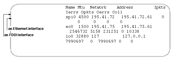
A workstation named minnie has an FDDI interface, xpi0, and an Ethernet interface, ec0. If the netif.options file is not altered, the default configuration is: xpi0 is assigned the IP address corresponding to minnie, and ec0 is assigned the IP address for gate-minnie. If there is no entry in /etc/hosts for gate-minnie, the secondary interface is not configured.
For example, minnie's /etc/hosts file contains this information:
195.41.91.3 minnie.disney.com minnie 195.41.184.2 gate-minnie.disney.com gate-minnie |
The unaltered /etc/config/netif.options file contains this information:
: if1name= : if1addr=$HOSTNAME : if2name= : if2addr=gate-$HOSTNAME |
This is the resulting configuration:
minnie (195.41.91.3) is configured as the primary FDDI interface.
gate-minnie (195.41.184.2) is configured as the secondary Ethernet interface.
To make the Ethernet (ec0) interface primary and the FDDI (xpi0) secondary for the system described in Example 2-1, you need to change the lines in the netif.options file to the following:
if1name=ec0 : if1addr=$HOSTNAME if2name=xpi0 : if2addr=gate-$HOSTNAME |
This is the result:
minnie (195.41.91.3) is configured as the primary Ethernet interface.
gate-minnie (195.41.184.2) is configured as the secondary FDDI interface.
To change the FDDI secondary interface name to fddi-minnie for the system described in Example 2-1 and Example 2-2, the /etc/hosts file and the /etc/config/netif.options file need to be altered.
The /etc/config/netif.options file must have the following entries:
if1name=ec0 : if1addr=$HOSTNAME if2name=xpi0 if2addr=fddi-$HOSTNAME |
The /etc/hosts file must have the following entries:
195.41.91.3 minnie.disney.com minnie 195.41.184.2 fddi-minnie.disney.com fddi-minnie |
During system startup and anytime it is invoked specifically, the shell command file /etc/init.d/network configures and initializes the network interfaces and software. Some of the script's procedures are accomplished by calling other utilities and reading configuration files. Some of the tasks the /etc/init.d/network command file performs are:
Determines the station's hostname. This information is defined in the /etc/sys_id file.
Determines the network hardware and interfaces available in the operating system. This information can be viewed with the hinv command.
Determines the ordering for the network interfaces. This information is defined in the /etc/config/netif.options file. If the netif.options file has not been altered, the default ordering is configured (explained in “Default Configurations” and defined within the network script).
Determines the network connection name for each network interface. This information is defined by the if#addr lines in the /etc/config/netif.options file. If the netif.options file has not been altered, the default names (explained in “Default Configurations” and defined in the network script) are used.
Determines the IP address for each interface by looking up each network connection name in the /etc/hosts file.
Determines the settings for each network interface's operational parameters. This information is defined in the /etc/config/ifconfig-#.options. If an ifconfig-#.options file does not exist for the interface, the default settings are assigned (described in “Default Configurations”).
Configures the number of network interfaces specified by the
if_ num variable in the network script.Starts (enables) each successfully configured interface.
The results of the network script's configuration can be viewed with the /usr/etc/netstat -i and /usr/etc/ifconfig commands.
Ethernet is automatically configured as the secondary network interface. It is assigned a network connection name of gate-hostname. This section provides instructions for changing the name used for the Ethernet network connection.
If a station does not have a second entry in the /etc/hosts file, the system does not configure a second network interface.
To configure Ethernet with a different /etc/hosts entry (for example, ether-hostname), follow these instructions:
Log on as superuser and open the /etc/config/netif.options file with your favorite editor.
Change the following line:
: if2addr=gate-$HOSTNAME
to
if2addr=newname
or
if2addr=newname-$HOSTNAME
Save and close the file.
Use one of the following commands to verify that the name you have entered in the netif.options file exists in the /etc/hosts file or hosts database. If the name does not exist, follow the instructions in “Network Connection Names and IP Addresses” to modify the /etc/hosts file.
% /sbin/grep name /etc/hosts
% /usr/bin/ypmatch name hosts
name is either the new name or newname-hostname.
If this is your final configuration change, go to the subsection “Build Configuration Changes Into the System” to finish.
There is no default configuration for FDDI network interfaces other than the first one. If a system has two or more FDDI connections, you need to add a pair of lines to the /etc/config/netif.options file for each additional FDDI network interface and possibly change the if_num variable in the /etc/init.d/network file.
The following lines are an example of netif.options entries for a system with three FDDI connections and one Ethernet. The lines for the first and second network interfaces have not been edited, so the default configuration for a primary FDDI and secondary Ethernet are automatically configured.
: if1name= : if1addr= : if2name= : if2addr= if3name=xpi1 if3addr=fddi2-goofy if4name=xpi2 if4addr=fddi3-goofy |
The network connection names (for example, fddi3-goofy) must exist in the /etc/hosts file.
The following is a single line in a network file that has been altered to configure twelve network interfaces:
if_num=12 |
To change the default settings for operational parameters (summarized in Table 2-4), create or edit the /etc/config/ifconfig-#.options file for the network interface. The pound sign (#) in the filename must match the number in the netif.options file that was used to configure the network connection. For example, for the netif.options line if3name=xpi0, create or edit the file /etc/config-3.options.
The following is an example of the contents of an /etc/config/ifconfig-#.options file. This file enables the IP address resolution protocol, sets a route metric, and specifies a subnetwork mask for the associated network:
arp metric 9 netmask 0xFFFFFF80 |
Complete instructions for configuring operational parameters are provided in the device configuration instructions in IRIX Admin: Networking and Mail.
By default, the routing daemon (routed) is started and IP forwarding (in the operating system) is enabled whenever a system has two or more network interfaces. This default configuration causes the system to advertise itself as a router to other systems on the networks, maintain tables of routes it knows, and to transfer (that is, route, forward) packets between its networks whenever it encounters packets that need to be routed in order to be delivered.
If your station has two (or more) network interfaces and you do not want the system to transfer or route packets between its networks or to advertise itself as a router, follow the steps in the examples below for the configuration you want.
This example disables the capability to forward data from one network to another and advertisement of all routing information. (This configuration does not disable the routing daemon's maintenance of routing tables, only its advertisement of the routing information.)
Edit the /etc/config/routed.options file so that it contains the characters -hq. This prevents the system from advertising its network connections (routes) or its presence (the host route) on any of the system's networks.
Edit the /var/sysgen/master.d/bsd file so that the line containing
int ipforwarding = 1 is changed to int ipforwarding = 0. This prevents the system from passing (transferring) any messages between its networks.Go to the subsection “Build Configuration Changes Into the System” to finish.
This example allows data to be forwarded from one network to another, but prevents the system from advertising its network connections (thus preventing the system from becoming known as a router).
Edit the /etc/config/routed.options file so that it contains the characters -hq. This causes the system to refrain from all rout advertising; it does not advertise its network connections (routes) and it does not advertise its own presence has a host (host routes) on its connected networks.
Go to the subsection “Build Configuration Changes Into the System” to finish.
This example allows data to be forwarded from one network to another and prevents the system from advertising its network connections (thus preventing the system from becoming known as a router). However, it allows the system to advertise its own presence as a host on the network attached as its primary network interface.
Edit the /etc/config/routed.options file so that it contains the characters -hmq. This causes the system to advertise (on all its connected networks) its presence as a host (the host route) on its primary network, but prevents the system from advertising its network connections and other host routes.
Go to the subsection “Build Configuration Changes Into the System” to finish.
For more information, see the routed(1M) and chkconfig(1M) man pages and the comments in the /var/sysgen/master.d/bsd file.
To build your network interface or driver configuration changes into the operating system, follow the procedure that is appropriate:
If the FDDI board has not been installed, do not rebuild the operating system now. Instead, follow the instructions in the FDDI board's installation guide or installation instructions to install the board.
If the FDDI board is installed, rebuild the operating system, and reboot to start using the new operating system with these commands:
% /sbin/su
Password: thepassword
# /etc/autoconfig
Automatically rebuild the operating system (y/n)? y
# /etc/reboot
The FDDIXPress board should be installed after the FDDIXPress software has been installed and configured. The instructions for installing an FDDI board are described in the board's installation guide or installation instructions.
The following is an overview of the procedure for installing the FDDIXPress product (software and hardware). The steps must be performed in the order shown.
Install the FDDIXPress software.
Perform these required configuration tasks:
Update your station's name(s) and IP address(es) in the /etc/hosts file. Instructions are provided in “Network Connection Names and IP Addresses”.
Configure the network interface(s). Instructions are provided in “Configure the Station's Network Interfaces”.
Install the FDDI board. Follow the instructions in the board's installation guide or installation instructions.
Installation of the board includes the following three steps. The FDDI connection will not function if you do not finish your installation with these steps:
Restart the system.
Answer yes to the prompt Automatically rebuild the operating system (y/n)?
Reboot the system.
(Optional) When you finish installing the board, continue with “Configure the Environment for User Friendliness and Safety (Optional)” to make your station's environment user friendly and safe.
Verify the FDDI connection. Instructions are provided in “Verifying the FDDI Connection”.
This section describes how to make your environment user friendly and safe. All procedures in this section are optional.
Four actions are recommended:
Set the path variable to include the SMT commands.
Create backup copies of important FDDIXPress files.
For sites without an NIS service: Create an /etc/ethers file so that names can be used with SMT commands instead of MAC addresses.
For sites with an NIS service: Create local copies of the ethers and hosts databases.
To invoke the SMT commands from any directory, the system must know where the commands reside. This section shows how to configure your environment so that the SMT commands are always available, regardless of the directory you are currently logged into.
If you do not configure the path, you must type the complete path to the directory where the SMT commands reside each time you invoke an SMT command.
Find the path to the SMT commands by reading any of the SMT command man pages. For example, enter the command:
% /usr/bin/man smtring
In the display that appears in your shell window, the text under the heading SYNOPSIS indicates the path. Make note of the path; it is everything up to, but not including, the command name. In the following display, /usr/etc/ is the path:
NAME
smtring - examines the state of FDDI ring
SYNOPSIS
/usr/etc/smtring [-adn] [-i interval] . . .
Open your .login file (or .cshrc file) with your favorite editor. For example, type a command line like this:
% /usr/sbin/jot /usr/people/yourloginname/.login
Locate the line that sets the path variable. The line looks like this:
set path=(. ~/bin /usr/bsd /usr/sbin /usr/lib /etc)
At the end of the path variable's last line, but before the closing parenthesis, add the new path. For example, if you were editing the example .login (or .cshrc) file, it should look like this example:
set path=(. ~/bin /usr/bsd /usr/sbin /usr/lib /etc /usr/etc)
The FDDIXPress SMT commands use MAC (physical) addresses to contact other FDDI stations on the ring. If you want to use the commands with names, instead of MAC addresses, your system must have access to an ethers database. (The ethers database maps physical addresses—MAC and Ethernet addresses—to network connection names.) Your station can obtain ethers database information from the site's Network Information Service (NIS) or from a local /etc/ethers file.
| Note: If any of your station's networks uses an NIS server, this procedure must be done at the NIS server, not on the local station. |
Edit the /etc/ethers file so it lists this station's MAC address and those of all the other stations on the FDDI ring:
Open a shell window and log on as superuser.
Use the /usr/etc/netstat -ia command to determine the MAC address of your station's FDDI board and the name of the FDDI interface. Be sure to find the MAC address for the FDDI board (for example, the MAC address listed under xpi0 or ipg0), not the Ethernet board (for example, ec0). In a default configuration, FDDI is the first interface listed. The MAC address is the number displayed in hexadecimal format, as shown in Figure 2-2.
Open the /etc/ethers file with your favorite editor.
Add a line to the /etc/ethers file that specifies the FDDI board's MAC address and the station's FDDI network connection name. In the /etc/ethers file, use the format displayed with the /usr/etc/netstat command for the MAC address and network connection name:
x:x:x:x:x:x networkconnectionname # comments
x:x:x:x:x:x is the 48-bit, hexadecimal MAC address of each network interface board. Each x represents one byte and can be a hexadecimal numeral from 0 to ff. The networkconnectionname corresponds to the name in the /etc/hosts file that is paired with the FDDI IP address. Comments start after the # character and are optional.
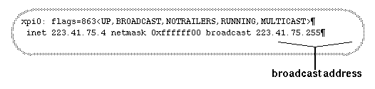
In another shell window, determine the broadcast address for your network by using the following command. The broadcast address is the sequence of digits displayed in the location illustrated in Figure 2-3.
% /usr/etc/smtconfig networkinterfacename
Using the broadcast address from step 5, make each station on the ring provide its MAC address and network connection name:
% /usr/etc/ping -r -c 10 broadcastaddress
Display the gathered information:
% /usr/etc/arp -a
Copy all the displayed MAC addresses and host names into your /etc/ethers file. Be sure to use the proper format as explained above and shown in Example 2-7.
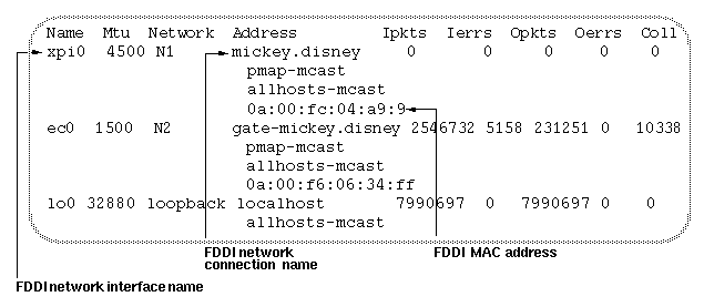
In this example, a station with a hostname of goofy, shows first a portion of an arp display, and second a corresponding portion of the /etc/ethers file. goofy has two network interfaces and has been configured with the default configurations. Note that the arp display does not list goofy's information.
The arp display:
mickey.disney.com (187.41.75.61) at a:0:69:6:34:ff donald.disney.com (187.41.75.1) at a:0:69:2:4:45 minnie.disney.com (187.41.75.5) at a:0:69:2:15:ff |
The /etc/ethers file:
a:0:69:da:5c:f goofy# local FDDI MAC addr 2:c:1f:1:e2:88 gate-goofy# local Ethernet addr a:0:69:6:34:ff mickey# an FDDI remote station a:0:69:2:4:45 donald# an FDDI remote station a:0:69:2:15:ff minnie# an FDDI remote station |
The above addresses can also be in this format:
0a:00:69:da:5c:0f goofy 02:0c:1f:01:e2:88 gate-goofy |
For more information, see the ethers(4), ping(1M), and arp(1M) man pages. For more information about the role of the /etc/ethers file, see IRIX Admin: Networking and Mail. For information about NIS, see the NIS Administration Guide and man pages.
Some of the FDDIXPress tools and commands (such as smtping and smtstat) depend on the /etc/ethers file (either local or on the NIS server) to know stations by their network connection names instead of by their MAC addresses. The /etc/ethers file maps MAC addresses to network connection names. You need to enter each FDDI station into the ethers database. (The file /etc/ethers is the ethers database.) If you do not update this database, FDDIXPress commands know stations only by their MAC addresses, in hexadecimal numerical format and Ethernet order, as defined in the Glossary.
The stations listed by arp -a are stations that your station has communicated with in the last few minutes. You can add entries to the arp display by invoking ping name or ping IPaddress.
If your site uses a Network Information Service (NIS) server, you may want to keep local (backup) copies of the ethers and hosts files for use when the NIS server is unavailable. (The local copies are not used as long as NIS is available.) For example, an NIS server could become unavailable when the FDDI ring wraps. If you decide to keep local backup copies, remember to update them when changes are made.
Type the following command lines to make local copies of /etc/hosts and /etc/ethers files, including the changes the network administrator has made to the database:
% /sbin/su Password: thepassword # /usr/bin/ypcat hosts > /etc/hosts # /usr/bin/ypcat ethers > /etc/ethers |
Do not perform this step until you are certain the network administrator has made all the changes pertaining to your station.
Files can become corrupted. It is a wise practice to keep backup copies of important files. To create backup copies of two FDDIXPress files that the SMT module (daemon) uses frequently, follow this procedure.
Performing this step can save you from reinstalling the FDDIXPress software if either file becomes corrupted or is deleted.
To verify that the station's FDDI connection is working, follow the steps in this section. Many of these steps use the smtstat -s command to view key items from the SMT information database. For details on how to use the smtstat command, see “Display SMT Information (MIB)”. If any of the following tests fail, see Chapter 4 for troubleshooting ideas.
Open a shell window.
Type the following command to verify that the FDDI board is recognized by the system software:
% /sbin/hinv
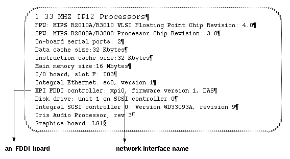
The hinv display, shown in Figure 2-4, lists all the hardware known to the system. An FDDI controller must display in the list. If an FDDI controller is not listed, refer to “Recognition of Board by Software”.
List all network interfaces on the system. An FDDIXPress interface, such as ipg# or xpi#, must be listed.
% /usr/etc/netstat -in
If the listing does not include an FDDI network interface, the FDDIXPress software may not have been installed, may not be configured, or may not be built into the operating system. Fix the problem before continuing.
Invoke the report display for the first FDDIXPress interface:
% /usr/etc/smtstat -I FDDIinterface -s
If an error message displays, look up the error message in Appendix A for troubleshooting instructions.
Verify that the FDDI board sees the ring's token.
Type z to reset the counters and start accumulating. The accumulating total displays every second.
Look at the “MAC state” field. It should display ACTIVE.
Watch the “tokens” field for 15 seconds. The number should increment rapidly. If the “tokens” field does not increment, refer to “Token Count Not Incrementing”.
Verify that the ports are working.
For a dual ring DAS, the following fields should have the statuses shown:
                   Port B    Port A
neighbor           A         B
PCM state          ACTIVE    ACTIVE
PC withhold        NONE      NONE
conn state         ACTIVE    ACTIVE
tx line state      THRU      THRU
rcv line state     ILS       ILS
A WRAP entry indicates that the ring is wrapped at this port. This may be due to an illegal port connection or it may indicate a fault on the ring. If the WRAP is on port B, the fault domain starts somewhere upstream from this station; if the WRAP is on port A, the fault is downstream.
A WRAP entry on a DAS connected to a concentrator is functioning normally. If the ring is wrapped, refer to “Ring Is Wrapped”.
For an SAS, the following fields should have the statuses shown:
                   Port S
neighbor           M
PCM state          ACTIVE
PC withhold        NONE
conn state         ACTIVE
tx line state      THRU
rcv line state     ILS
A QLS or HLS entry on the transmit line state indicates the connection at this station is faulty. This may be due to an illegal port connection or it may indicate a faulty cable or connection. Follow the instructions in “Check Cables and Connectors” to correct the connection.
Verify that the optical signal is being received without errors.
Continue viewing the Port (#2) report.
Type r to view the totals accumulated since the last reboot.
Look at the “Link errors: short-term” field. The number should be 9 or greater. If the short-term link error value is less than 9, refer to “Link-Level Errors”.
Verify that there are no beacon or claim errors.
Type z.
Monitor the “Claims received” and “Beacons received” areas for 1 minute. The values should be close to zero for a ring functioning normally. If you observe an increase of two or more beacons or claims, wait a few minutes and repeat your observations two more times.
If you consistently see more than two additional claims or beacons during your monitoring periods, refer to “Too Many Claims or Beacons”.
Verify upstream and downstream neighbors:
Type 5 to view the Neighbors (#5) report.
In the bottom section of the display, verify that a nonzero address is listed for upstream and downstream neighbor stations. Ignore the “old” listings. If one or both of the neighbors are listed with an address of zero, refer to “Current Neighbor's Address Is Zero”.
Take note of the names or MAC addresses for the upstream and downstream neighbors. You will use these in a subsequent step. If the screen display lists MAC addresses only with no names, the /etc/ethers database has not been set up. The /etc/ethers database is an optional configuration task explained in “Setting Up the ethers File (Optional)”.
Type q to quit the report display.
Verify that this station can communicate with other stations on the ring.
Type one of the following commands for each of the station's neighbors:
% /usr/etc/smtping -c 10 fddinetworkconnectionname
or
% /usr/etc/smtping -c 10 MACaddress
Names and MAC addresses of other stations on your FDDI ring are listed in the /etc/ethers file or ethers database.
Verify that the message in the next-to-last line of the smtping display indicates less than 10 percent packet loss. If smtping does not elicit a response from a station, see “Cannot Communicate With Other Stations” for troubleshooting instructions.
If the ring is losing packets at a rate over 10 percent, see “High Rate of Packet Loss”.
[1] The network connection name is a name entered in the /etc/hosts file. This name is paired with an IP address. Each network interface must have one network connection name that is unique to the domain and one globally unique IP address.