This chapter describes how to install the Sirius Video option on the following Silicon Graphics platforms:
graphics: POWER Series, Crimson (Diehard II), Onyx (Eveready), and Skywriter
server: Challenge L (Eveready) and XL (Terminator), and POWER Series (Predator)
The installation procedure is divided into the following steps:
Preparing the chassis
Installing the Sirius Video panels on the I/O door
Verifying or changing the physical VME address on the board
Jumpering the Crimson or Onyx midplane or backplane, if slots are skipped
Attaching the PAB paddleboard to the DG board (graphics only)
Inserting the Sirius Video board
Attaching paddleboard and graphics cables (graphics only)
Attaching analog and digital internal cables
Installing the optional serial board into the breakout box
Attaching external cables
Restarting the system and installing the Sirius Video software
Testing the installation
Editing the system file for nonstandard setups
Setting up the system for Sirius Video with Multi-Channel Option installed
Other Silicon Graphics manuals contain instructions for exchanging circuit boards. Make sure you have the appropriate one(s):
InfiniteReality Graphics Upgrade Installation Instructionsfor Deskside and Rackmount Onyx Systems (108-0132-001)
CHALLENGE/Onyx Deskside Installation Instructions (108-7039-xxx)
CHALLENGE/Onyx XL Rackmount Installation Instructions (108-7042-xxx)
CHALLENGE and Onyx Retrofit Instructions (domestic version: 802-0107-002; international version: 802-0106-002)
Challenge/Onyx Rackmount Third Cardcage (CC3) Upgrade Instructions (release note, 802-0105-xxx): setting up third cardcage for Onyx rackmount
Single Tower Maintenance Manual (108-7002-xxx): Crimson and POWER Series systems
Make sure you have other pertinent release notes and Field Information Bulletins as well.
You need a flat-blade screwdriver and a Phillips screwdriver to install Sirius Video.
To prepare the chassis for installing the option, take chassis hardware issues into account:
If the chassis has InfiniteReality graphics, has the SCSI fan been upgraded?
Does the GE8 (or GE10 or GE10V) board have the correct CP chip?
Is the chassis wiring adequate?
What VME slot will the Sirius Video board go in, especially if other options are installed?
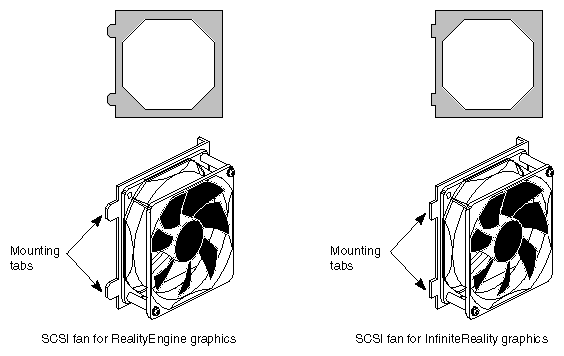
If the chassis has InfiniteReality graphics, make sure the SCSI fan has been upgraded. Figure 2-1 shows the difference in the mounting tabs.

Caution: The mounting tabs (prongs, tongues) on the SCSI fan for RealityEngine protrude far enough into the chassis to short out the PAB2 that connects onto the InfiniteReality graphics DG4 board. If you are installing the Sirius Video option in a system with InfiniteReality graphics, make sure the SCSI fan has been replaced. If it has not, you must install the new SCSI fan with the shorter mounting tabs; follow instructions in the InfiniteReality Graphics Upgrade Installation Instructions for Deskside and Rackmount Onyx Systems (108-0132-001).
If you are installing the Sirius Video option in a POWER Series or Crimson chassis with a graphics head, make sure that the CP chip on the GE8 (or GE10 or GE10V) board is uprevved. For the VO2 board to input to graphics, this chip must be CP2 revision B. As root, run
/usr/gfx/gfxinfo -v
A typical output of this command might be:
Graphics board 0 is "REV" graphics.
 Managed (":0.0") 1280x1024
 Display 1280x1024 @ 60Hz
 12 GE (GE10 rev. 0x7/011)
 4 RM4 boards (rev. 00102/00102/00102/00102)
 Large pixel depth
 10-bit RGBA pixels
 Not using Multi-Channel Option
The middle revision number for the GE board must be 1; in the example above, it is 0x7/011. If the middle number is not 1, you must swap the existing GE board with the corresponding GE board CP2 revision B:
GE8: 030-0546-001
GE10 for RealityEngine2 (Onyx): 030-0325-004 or (required for CC3) 030-0325-005
GE10V for VTX (Onyx): 030-0363-004 or (required for CC3) 030-0363-005
A single Sirius board requires as much current as an RM board. Make sure the chassis wiring is adequate:
deskside Onyx
Determine the number of devices already in the chassis and how many the customer plans to add. Make sure the chassis has 220 VAC wiring if it will have more than these quantities of these components:
– two RM boards
– two CPU boards, each with four R4400s
– seven disks
– three VME boards
If the chassis does not exceed the quantities of the components listed above, 110 VAC wiring is adequate.
deskside Onyx with InfiniteReality graphics
The VME power for the Onyx deskside InfiniteReality or i-Station system is variable. Depending on the line voltage and type of power boards used, the VME wattage available may be greater or less than that in RE2. All figures are based on use of the InfiniteReality 50-amp OLS.
Table 2-1 shows an example of wattage used by two different Silicon Graphics VME-based boards. Using both in the Onyx deskside system at the same time exceeds the allotted maximum VME wattage for most deskside Onyx systems (see Table 2-2). The second row of Table 2-1 gives the exception to this rule.
Table 2-1. Deskside Onyx VME Power Use Example
System Volts and Power Board Config.
VME Board Type
Watts Used at
+5 VVME Watts Still Available
110VAC with 1 RM6 using a 303, 305, and 512T
VME HIPPI
75
95
220VAC with 2 RM6s using a 303, 305, and 512T
VME Sirius (VO2)
110
320

Note: Power output is insufficient using 100 V Japanese line voltages. Only 220-240 V InfiniteReality or i-Station systems are supported for use in Japan. Table 2-2. Onyx InfiniteReality and i-Station VME Power
Configuration, Voltage, and Power Boards Used
Total +5V Available for VME and IO4 Mezz Boards[a]
Total +12V Available for VME Boards
110VAC with 1 RM6 using two 303s and a 512T
26 amps (130 watts)
5.7 amps (68 watts)
110VAC with 1 RM6 using a 303, 305, and 512T
34 amps (170 watts)
5.7 amps (68 watts)
220VAC with 2 RM6s using two 303s and a 512T
26 amps (130 watts)
5.7 amps (68 watts)
220VAC with 2 RM6s using a 303, 305, and 512T
86 amps (430 watts)
5.7 amps (68 watts)
[a] Assume an average use of 25 watts for each IO4 mezzanine board installed.
For more information, consult the InfiniteReality Graphics Upgrade Installation Instructionsfor Deskside and Rackmount Onyx Systems (108-0132-001).
rackmount Onyx
If the chassis has or will have a third cardcage, prepare the circuit so that it is easily changed to 3-phase when required. If the customer has no plans to include the third cardcage, the circuit for 220 VAC 1-phase power is adequate.
Make sure all users are off the target system.
Shut down the system. Open the chassis, removing the rear outer panel if necessary. Open the rear metal panel to expose the slots.
Plan where to install the Sirius Video (VO2) board.
VME slot required
The option can go into any available VME slot in any chassis.
Note: In the Crimson chassis, install the VO2 board in slot 2 only. The hardware on the Crimson I/O door does not allow space for the VO2 board in the leftmost VME slot. If you install the VO2 board in a slot other than the first available one (and this slot is not occupied by another VME board), you must jumper the backplane, as explained in Section 2.4, "Jumpering the Crimson or Onyx Backplane or Midplane," later in this guide.
An Onyx rackmount accepts up to six VO2 boards: two in CC2 and four in CC3.
space for paddleboard
Take into account that the paddleboard that you will attach to the DG2 board in graphics chassis extends into the space between the board slots and the I/O door. Avoid interference from the paddleboard and its cables.
system with Multi-Channel Option (MCO) installed
Because the pre-breakout box version of MCO can take all available slots on the I/O door, make sure there will be four slots available for the Sirius Video panels (see Figure 2-2). If there is not, one or more MCO I/O panels must be removed, with resulting loss of the use of channel(s); consult with the customer.
Note: You must reset DIP switches on the Sirius Video board for use in a system with the Multi-Channel Option installed, as explained in Section 2.3, "Verifying or Changing the Physical VME Address on the Board," later in this chapter. For nonstandard configurations, you must edit the file /var/sysgen/system/video.sm, as explained in Section 2.13, "Editing the System File for Nonstandard Setups," later in this chapter.
To install the four Sirius Video panels in the I/O door, follow these steps:
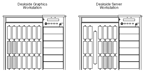
Remove four slot panel covers, two from the middle row of slots and two from the lower row, in a pattern like that shown in Figure 2-2.
Note: The configuration in Figure 2-2 is recommended. Regardless of the slots you choose, make sure the cables are long enough to reach the connectors on the VO2 board when it is installed. Install the DIGITAL 1 & 2 (digital input; p/n 018-0425-002) and DIGITAL 3 (output; p/n 018-0424-002) panels in the two top uncovered slots.
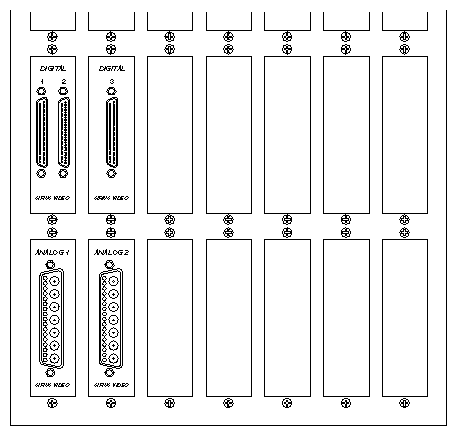
Install the ANALOG 1 (p/n 018-0471-001) and ANALOG 2 (p/n 018-0412-004) panels in the other two uncovered slots. Figure 2-3 shows the panels installed.
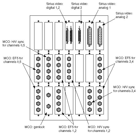
Caution: Always connect the internal and external analog video interface cables and I/O panels, even if the customer uses digital mode only. These cables carry signals besides analog video; for example, the analog cables control multiplexing between the parallel or serial digital input source. If you are installing Sirius Video in a system that has the I/O panel version (no breakout box) of Multi-Channel Option, position Sirius Video and MCO panels to avoid interfering with the MCO microstrip cables. For example, on a deskside system the MCO EF5 panels for channels 0,5 and 1,2 are better placed at the top of the I/O door to avoid pinching the MCO microstrip cables at the VS2 paddleboard. The MCO EF5 panel for channels 3, 4 can be mounted upside down at the bottom right corner of the I/O panel so that it clears the DG2 and paddleboard and the front plane. Figure 2-4 shows an example configuration.
Note that because the Multi-Channel Option board is connected to the DG2 via the PB2 paddleboard, Sirius Video cannot use the DG2 and thus cannot send live video to graphics. The capabilities of the Multi-Channel Option, however, are not affected.
| Caution: The VO2 board has active components on both sides; exercise care in handling it. Board components are extremely sensitive to electrostatic discharge. Wear a grounded wrist strap and use all appropriate antistatic handling procedure. |
The Sirius Video option sits on the VME16 bus; it connects to one pipe only.
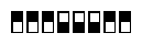
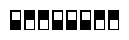
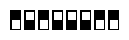
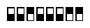
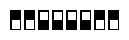
| Caution: VO2 board DIP switches are easily dislodged from the correct setting.Verify that they are at the default settings (01100000) shown in the first line of Table 2-3 in this section. |
Changing the default VME address for Sirius Video is required in three cases:
The board's address space conflicts with another A16 VME peripheral installed in the same system.
You are installing a second Sirius Video into the A16 VME bus.
A Multi-Channel Option is already present in the system.
All addresses should be on 256-byte boundaries (0x100, 256) for proper alignment. The option requires an address space of 0x100 (256) bytes.
The address is factory-set to 0x3000; Table 2-3 lists this setting and the three other legal addresses. Use these settings for Sirius Video in
Onyx or Challenge with no MCO installed
The Sirius Video board must be in the same CC3 as the RealityEngine to which it is connected. Each board must be at a unique address within the same CC3, but boards in different CC3s can share addresses. You can install up to four boards per CC3, of which only one can be connected to a RealityEngine.
Crimson or other MP-based system: normal operation without graphics
Crimson or other MP-based system: boards connected to pipe 0, with no MCO
| Note: Addresses 0x30 through 0xff are allowed, although addresses 0x30 through 0x3f are standard. To use an address other than the standard 0x30 through 0x3f, you must edit the kernel configuration file, as explained in Section 2.13, "Editing the System File for Nonstandard Setups," later in this chapter. |
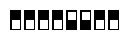
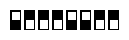
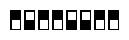
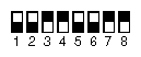
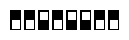
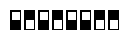
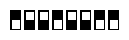
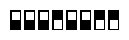
Table 2-3. Standard VME Addresses and DIP Switch Settings for Normal Operation (No MCO)
Physical Address | DIP Switch Setting | Switches | |
|---|---|---|---|
0x3000 (factory setting) |
| 5 and 6 are open, all other closed | |
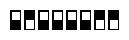
0x3100 |
| 1, 5, and 6 open, all others closed | |
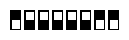
0x3200 |
| 2, 5, and 6 open, all others closed | |
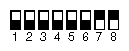
0x3300 |
| 1, 2, 5, and 6 open, all others closed |
 |
The DIP switches are near the bottom card ejector lever on the VO2 board and can be switched with the power on, if necessary. However, any change to DIP switch settings requires a kernel reconfiguration, followed by a system reboot (or else two system reboots).
For Sirius Video to work in a system with MCO installed, set addresses as shown in Table 2-4.
Table 2-4. Sirius Video VME Addresses for Systems With MCO Installed
MCO | Onyx or Challenge | Crimson or Other MP-based System |
|---|---|---|
Not present | 30, 31, 32, 33 regardless of pipe (0, 1, 2) | Pipe 0: 30, 31, 32, or 33 |
Present | 38, 39, 3a, or 3b regardless of pipe (0, 1, 2) | Pipe 0: 38, 39, 3a, or 3b |
DIP switch settings for these addresses are shown in Table 2-5.
Table 2-5. DIP Switch Settings for Use With Multi-Channel Option
Physical Address | DIP Switch Setting | Switches | |
|---|---|---|---|
0x3400 |
| 3, 5, and 6 open, all others closed | |
0x3500 |
| 1, 3, 5, and 6 open, all others closed | |
0x3600 |
| 2, 3, 5, and 6 open, all others closed | |
0x37000 |
| 4, 7, and 8 closed, all others open | |
0x3800 |
| 4, 5, and 6 open, all others closed | |
0x3900 |
| 1, 4, 5, and 6 open, all others closed | |
0x3a00 |
| 2, 4, 5, and 6 open, all others closed | |
0x3b00 |
| 3, 7, and 8 closed, all others open | |
0x3c00 |
| 3, 4, 5, and 6 open, all others closed | |
0x3d00 |
| 2, 7, and 8 closed, all others open | |
0x3e00 |
| 1, 7, and 8 closed, all others open | |
0x3f00 |
| 7 and 8 closed, all others open |
| Caution: The VO2 board has active components on both sides; exercise care in handling it. Board components are extremely sensitive to electrostatic discharge. Wear a grounded wrist strap and use all appropriate antistatic handling procedures. |
The next step depends on the situation:
If you are skipping VME slots, follow instructions in the next section.
If you are installing Sirius Video in a graphics workstation and are not skipping VME slots, skip to Section 2.5, "Attaching the PAB Paddleboard to the DG Board (Graphics Only)."
If you are installing Sirius Video in a server and are not skipping VME slots, skip to Section 2.6, "Inserting the Sirius Video Board."
If you are installing any VME board in an Onyx deskside or rackmount chassis and are skipping slots, you must jumper the backplane or midplane. If the backplane or midplane is not jumpered, Sirius Video might not be reported in the hinv output.
The procedure varies, depending on whether you are installing Sirius Video in
a Crimson or an Onyx deskside system
cardcage 2 of an Onyx rackmount system
cardcage 3 of an Onyx rackmount system
| Note: For POWER Series, follow the usual procedure as explained in the chassis documentation. |
Insert jumpers (p/n 9090003) into the jumper banks that correspond to the VME slot numbers you are skipping. For example, if you are skipping the first VME slot, insert jumpers into jumper bank 1. To jumper a bank, connect all five pairs of posts with jumpers.
| Note: In a Crimson chassis, install the VO2 board in slot 2 only; otherwise, the door will not close. If slot 1 is not occupied by another VME board in this chassis, you must jumper the backplane. |
Follow these guidelines:
If you are skipping the first VME slot (that is, slot 5 in an Onyx or slot 7 in a Challenge system) to use the next one, place five jumpers in the jumper bank designated as slot 1 (see Figure 2-5).
If you are skipping the first two VME slots to use the third one, place jumpers in banks 1 and 2.
If boards occupy VME slots 1 and 3, and slot 2 is vacant, place jumpers in bank 2.
Figure 2-5 shows placement of the jumpers.
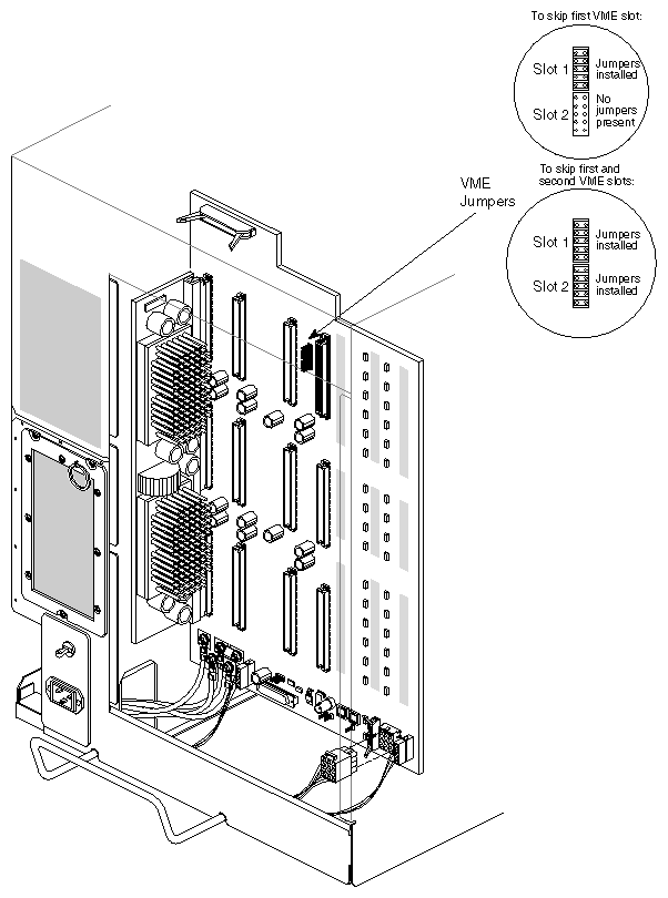
Insert jumpers (p/n 9090003) into the jumper banks that correspond to the VME slot numbers you are skipping. Jumper the VME slots only if you are leaving gaps between the VCAM in slot 16 and the VO2 board or any other VME boards, or if you are skipping slots between VME boards.
Corresponding to each slot is a bank of five jumpers, as shown in Table 2-6.
The jumper banks are located on the cardcage 1 side of the midplane, between the power bus slots, as shown in Figure 2-6.
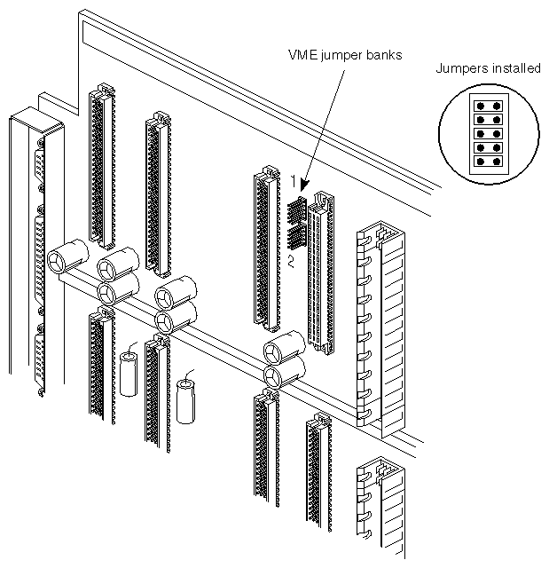
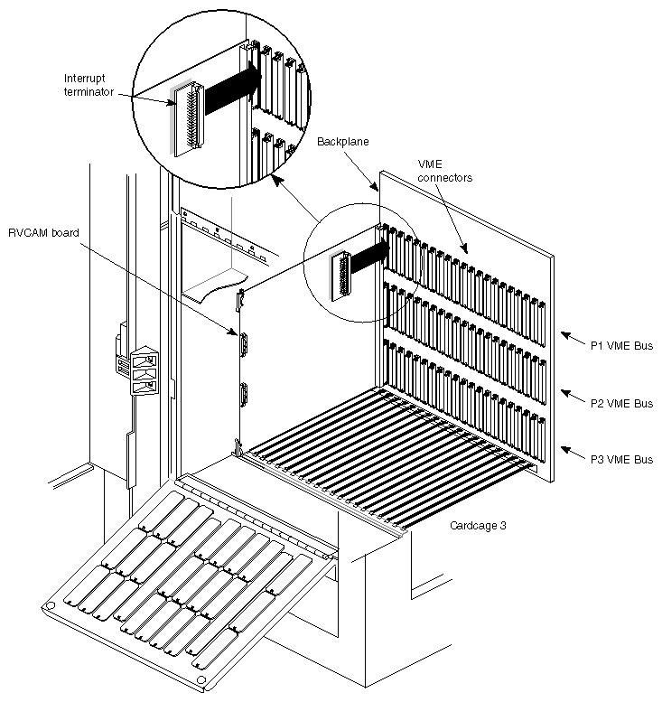
Typically, between each remote VCAM and each graphics head in cardcage 3 are three VME slots. If no other VME cards occupy the slot(s) to the left of the VO2 board, you must attach an interrupt board (p/n 030-0516-00x) to the top connector (P1 VME bus connector) for each slot on the backplane, as shown in Figure 2-7. Interrupt boards are required because there are no jumper banks for slots on the cardcage 3 backplane.
If you are installing Sirius Video in a server, proceed to Section 2.6, "Inserting the Sirius Video Board."
If you are installing Sirius Video in a graphics platform, you must attach a paddleboard to the DG board:
the PAB1 paddleboard (p/n 030-0506-005) attaches to the DG2 board
the PAB 2 paddleboard (p/n 030-0766-003) attaches to the DG4 board
Installing these paddleboards is explained in separate sections.
Follow these steps:
| Note: If a Multi-Channel Option is already installed in the chassis, skip this section; the PAB1 paddleboard and its cables are not used in this case. |
Detach the 24W7 cable connector going to the EF7 board from the DG2 board. Detach the twisted-pair SWAP READY cable (GE10 in Onyx and Challenge) or the both twisted-pair cables, stereo and SWAP READY (GE8 in POWER Series).
Remove the DG2 board from the chassis and lay it on a nonstatic surface.
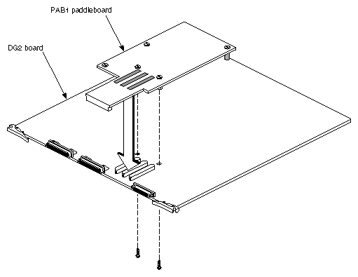
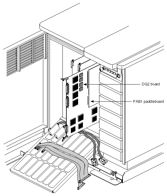
Align the three microstrip connectors near the middle of the paddleboard to the P6, P7, and P8 connectors on the DG2 board, as diagrammed in Figure 2-8.
Supporting the DG2 board from the other side, carefully push the PAB1 paddleboard onto the connectors. Be careful not to bend the DG2 board.
Caution: Be extremely careful not to bend or smash the pins in the microstrip connectors on the paddleboard; they are very fragile. These pins cannot be reliably repaired. If they are damaged, replace the entire paddleboard. If you need to remove the PAB1, rock it from side to side as you pull it off the DG2 board.
From the other side of the DG2 board, screw two nylon screws (p/n 9300407) into the standoffs on the paddleboard that are nearest the connectors. The other standoffs are not screwed in; they provide support only.
Reinsert the DG2 board most of the way into its slot, but not all the way.
Figure 2-9 shows the DG2 board with the PAB1 installed.
Reconnect the 24W7 connector and the SWAP READY (twisted pair) cable.
Follow these steps:
Detach from the DG4 board the connector of the standard (68-pin) cable going to the I/O panel, and, if present, also the connector of the 80-pin cable (present if the board is a DG4-8).
Carefully remove the DG4 board from the chassis, making sure that metal tongues on the SCSI fan assembly do not damage the board as you remove it. These tongues can protrude through the sheet metal and into the mechanical area occupied by the DG4 board.
Lay the DG4 board on a nonstatic surface.
Align the long connector at the edge of the paddleboard to the long connector on the DG4 board, as diagrammed in Figure 2-10.
Figure 2-10. Attaching Standoffs to the DG4 Board for the PAB2 Paddleboard: InfiniteReality Graphics
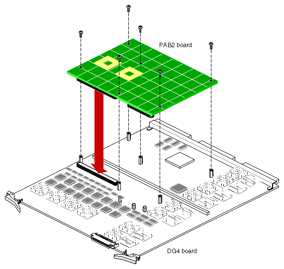
Supporting the DG4 board from the other side, carefully push the PAB2 paddleboard onto the connectors. Be careful not to bend the DG4 board.
From the other side of the DG4 board, screw six nylon screws (p/n 9300407) into the standoffs on the paddleboard that are nearest the connectors.
Make sure the SCSI fan has been replaced, as required for InfiniteReality graphics.
Caution: The mounting tabs (prongs, tongues) on the SCSI fan for RealityEngine protrude far enough into the chassis to short out the PAB2 attached to the InfiniteReality graphics DG4 board. Figure 2-11 shows the difference in the mounting tabs.
If the fan must be replaced, follow instructions in the InfiniteReality Graphics Upgrade Installation Instructions for Deskside and Rackmount Onyx Systems (108-0132-001).
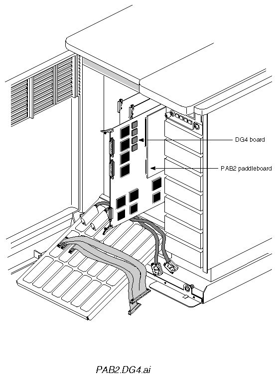
Reinsert the DG4 board most of the way into its slot, but not all the way.
Caution: Make sure that the mounting tabs on the SCSI fan assembly do not scrape PAB2 components as you reinsert the DG4. Figure 2-12 shows the DG4 board with the PAB2 installed.
Reattach the cable(s) connecting the DG4 to the I/O panel.
To insert the Sirius Video board (labeled VO2), follow these steps:
| Caution: The VO2 board is physically fragile and has active components on both sides, including thousands of tiny surface-mount parts, many of them on the back side. Exercise extreme care in handling the VO2. Setting the board down on a bench or the top of the chassis is likely to damage parts on the back side. Board components are extremely sensitive to electrostatic discharge; wear a grounded wrist strap and use all appropriate antistatic handling procedures |
Grasp the Sirius Video board so that your hands are on the ejector tabs and the component side of the board faces right.
Position the Sirius Video board in the card guides in the VME slot you have selected and push the board in about halfway. If you are installing the VO2 in a server, insert the board all the way.
Caution: Check for clearance on both sides of the VME slot you have selected. In particular, check for ribbon cables to the immediate left of the slot you have selected. Hold any cables flat against their respective boards while inserting the Sirius Video board to prevent them from being chafed by Sirius Video board components. Note: In the Crimson chassis, install the VO2 board in slot 2 only; the black video connector on the VO2 board blocks the PP2 board at the front panel, preventing the front door from closing. If you are skipping VME slots in any chassis, you must jumper the backplane, as explained earlier in this guide.
Make sure that the DIP switch settings are the way you want them; switches can become flipped during installation.
Caution: If you are inserting more than one Sirius Video board in a chassis, slide both of them into the card guides simultaneously. This technique avoids damage to the boards that might result because of limited clearance where the high caps are located. In a graphics workstation, do not insert the boards in all the way until cabling is done, as described in the next section.
If you are installing Sirius Video in a server, skip the next section and proceed to Section 2.8, "Attaching Analog and Digital Internal Cables."
If you are installing Sirius Video in a graphics workstation, attach the following internal cables:
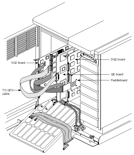
for the PAB1 used with RealityEngine, PA CTL and PA DATA cables (p/n 018-0421-002 and 018-0422-002): DG2 paddleboard (PAB1) to VO2 board
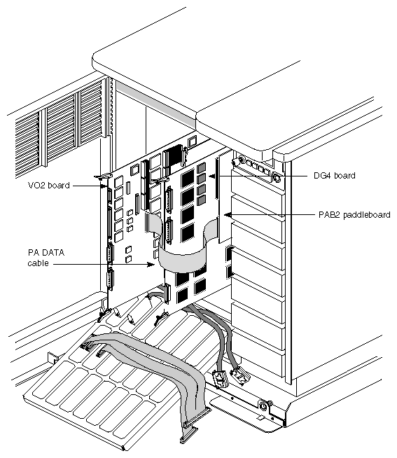
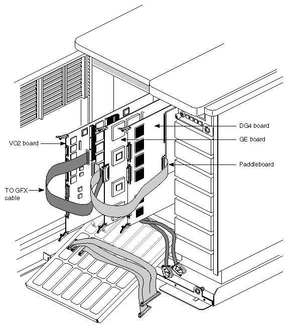
for the PAB2 used with InfiniteReality graphics, PA DATA cable only (018-0422-002): DG4 paddleboard (PABs) to VO2 board
for both PAB1 and PAB2, the TO GFX cable (p/n 018-0423-002): GE board to VO2 board
Attaching cables to the paddleboard is explained in separate sections for each type of paddleboard.
For RealityEngine graphics, follow these steps:
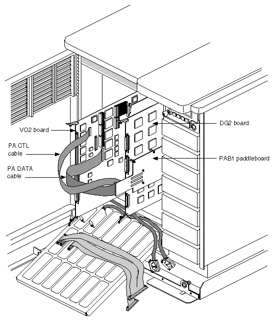
Attach the connector of the PA CTL cable (p/n 018-0421-002; 50-position) to the small connector on the paddleboard; the cable connectors are keyed. Attach its other end to the connector labeled PA CTL on the VO2 board; it is the top of the three connectors on the board proper.
Attach the connector of the PA DATA cable (p/n 018-0422-002; 80-position) to the large connector on the paddleboard; the cable connectors are keyed. Attach the other end to the connector labeled PA DATA on the VO2 board; it is the bottom of the three connectors on the board proper.
Figure 2-13 shows this placement.
Caution: Switching the PA DATA cable and the TO GFX cable can result in damage to the VO2 board (signal/ground short).
If a PAB1 interface cable exits in the wrong direction, reverse the direction by using the connector at the other end of the cable instead.
Note: If you are installing the Sirius Video option in a POWER Series or Crimson chassis, make sure that the CP chip on the GE board is uprevved. For the VO2 board to input to graphics, this chip must be CP2 revision B. See Section 2.1, "Preparing the Chassis," earlier in this guide. Attach the TO GFX cable to the GE8, GE10, or GE10V board:
If necessary, pull the GE board partway out of its slot.
On the TO GFX cable, align the KEL connector's Pin 1 arrow with the arrow on the GE board's graphics connector (arrow at the bottom); seat the connector.
Mate the keying notch on the cable's other connector to the keying notch on the connector silkscreened TO GFX on the VO2 board; it is the middle of the three connectors on the board proper. Both connectors are keyed on the right side. See Figure 2-14.
Note: If a Multi-Channel Option is already installed in the chassis, you must reset DIP switches on the board; see Section 2.3, "Verifying or Changing the Physical VME Address on the Board," earlier in this chapter. Insert the DG and Sirius Video boards completely into the chassis. Make sure the boards snap into the backplane connectors.
For InfiniteReality graphics, follow these steps:
Attach the connector of the PA DATA cable (p/n 018-0422-002; 80-position) to the large connector on the paddleboard; the cable connectors are keyed. Attach the other end to the connector labeled PA DATA on the VO2 board; it is the bottom of the three connectors on the board proper. See Figure 2-15.
Attach the TO GFX cable to the GE12 board:
If necessary, pull the GE board partway out of its slot.
On the TO GFX cable, align the KEL connector's Pin 1 arrow with the arrow on the GE board's graphics connector (arrow at the bottom); seat the connector.
Mate the keying notch on the cable's other connector to the keying notch on the connector silkscreened TO GFX on the VO2 board; it is the middle of the three connectors on the board proper. Both connectors are keyed on the right side. See Figure 2-16.
Insert the DG and Sirius Video boards completely into the chassis. Make sure the boards snap into the backplane connectors.
In all workstations, attach the cables from the I/O door to the board:
analog cables (p/n 018-0471-001 and 018-0412-004)
digital cables (in: p/n 018-0425-002; out: 018-0424-002)
| Caution: Always connect the internal and external analog video interface cables, even if the customer uses digital mode only. These cables carry signals besides analog video; for example, the analog cables control multiplexing between the parallel or serial digital input source. |
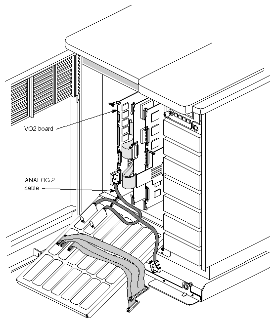
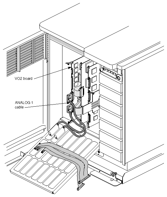
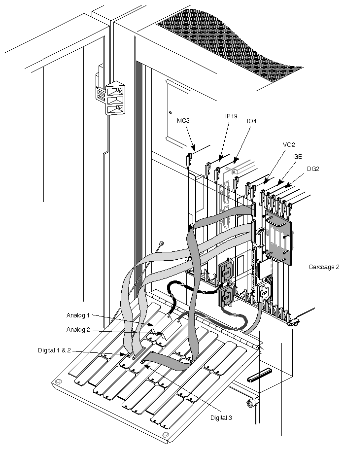
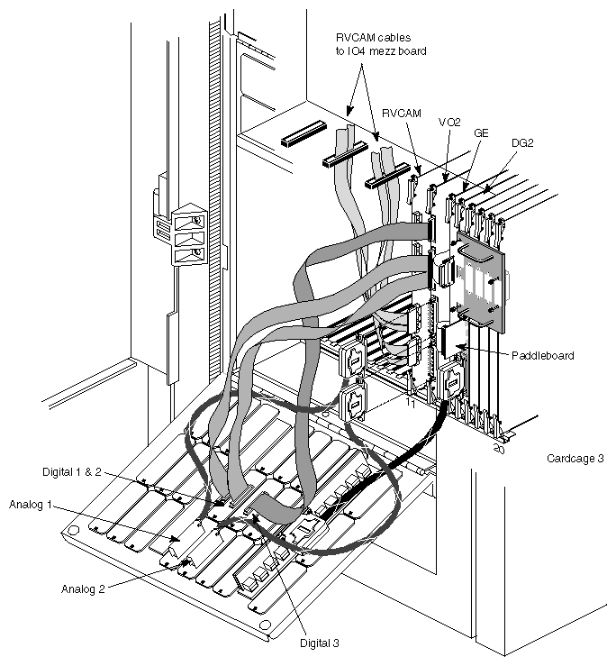
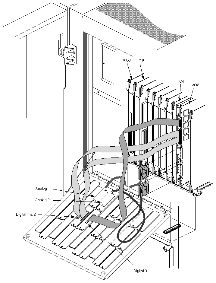
Attach the connector for the ANALOG 2 cable to the bottom analog connector. Because of the size of the connector covers and the stiffness of the heat-shrink tubing, it's easier to attach this cable first. Figure 2-17 shows the connection.
Attach the ANALOG 1 cable to the upper analog connector, as shown in Figure 2-18.
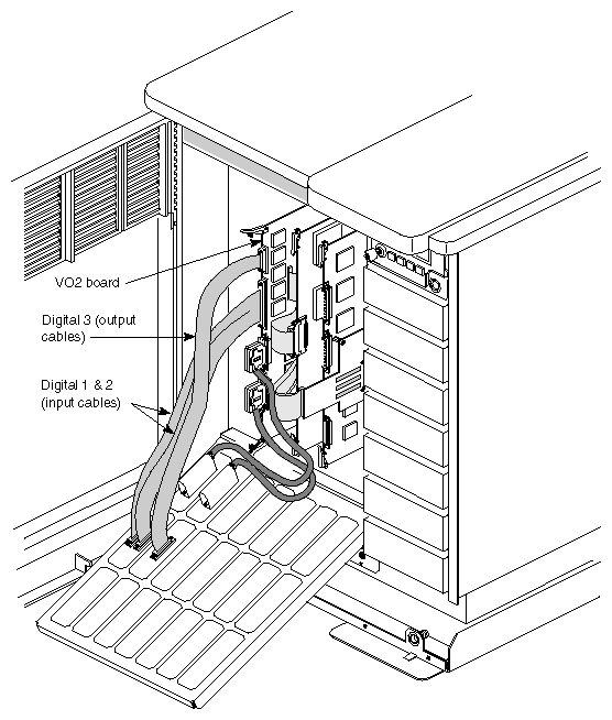
Note: You must bend the ANALOG 1 cable slightly to fit around the 24W7 connector for ANALOG 2. Attach the large connector (100-position) of the DIGITAL 1 & 2 cable to the large (100-position) connector labeled DIGITAL 1 & 2 on the VO2 board.
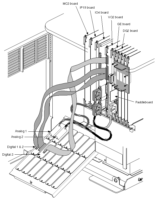
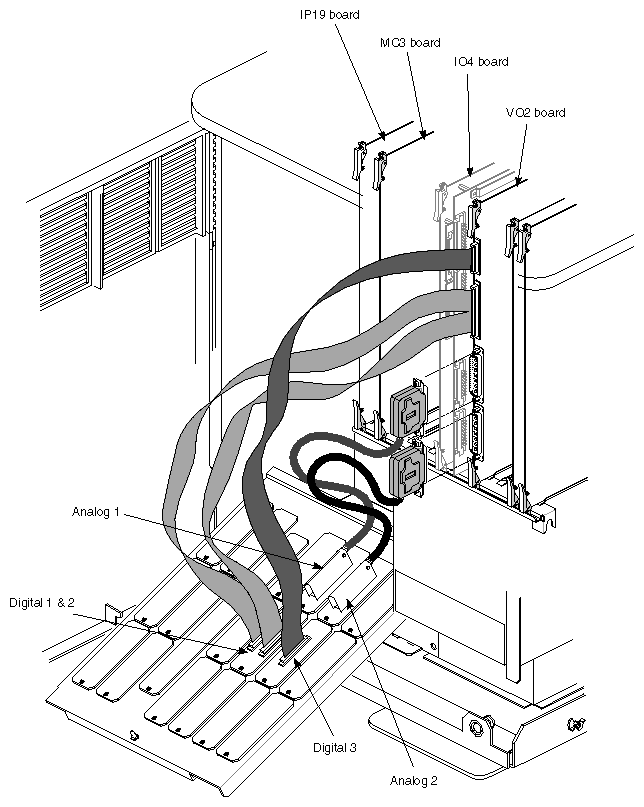
Attach the small connector (50-position) of the DIGITAL 3 cable to the smaller (50-position) connector above the DIGITAL 1 & 2 connector on the VO2 board. This connector is labeled DIGITAL 3 in silkscreen on the board. Figure 2-19 shows all internal cables attached in a graphics workstation.
Note: For clarity, paddleboard and graphics cables are shown shorter than they really are. The next figures show complete installations in various chassis.
Note: The Sirius Video must be in the same cardcage as the RealityEngine to which it is connected. Each board must have a unique address within the same cardcage; boards in different cardcages can have the same address. Each cardcage can accommodate up to four Sirius Video boards, of which only one can be connected to the RealityEngine; the others behave as if they were in a server chassis.
Note: The Sirius Video must be in the same cardcage as the RealityEngine to which it is connected. Each board must have a unique address within the same cardcage; boards in different cardcages can have the same address. Each cardcage can accommodate up to four Sirius Video boards, of which only one can be connected to the RealityEngine; the others behave as if they were in a server chassis.
When you are finished, carefully and gradually close the I/O door.
Caution: Exercise extreme care in closing the I/O door so that the paddleboard and cables are not damaged. This process may require repositioning or folding cables, or possibly reinstalling the VO2 board in a different location.
If you are installing the serial option in the breakout box, proceed to the next section. If you are not, proceed to Section 2.10, "Attaching External Cables."
If the customer has ordered D4-SD1, which provides serial digital video capability to the Sirius Video breakout box, follow these steps to install it:
If necessary, unplug the breakout box; unscrew the four screws on top to remove its cover.
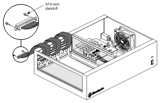
Unscrew the bottom connectors of the three ribbon cables from the chassis. Reserve the screwlocks.
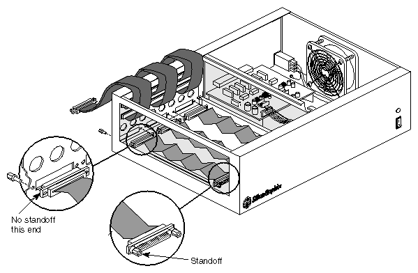
Attach two 3/16-inch standoffs, included in the SD1 kit, to each of the cable connectors, as shown in Figure 2-25.
Pop out the eight round BNC hole covers for the serial ports.
Attach the plain ends (no standoffs) of the three ribbon cables (p/n 018-0427-002) from the SD1 kit to the three D connector openings at the bottom of the breakout box, as shown in Figure 2-26. Use the reserved screwlocks to secure them.
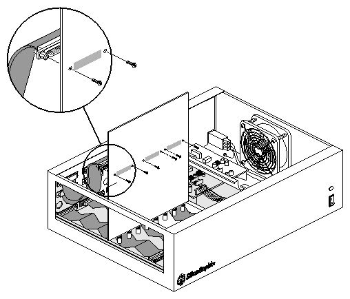
Place the SD1 board upright into the breakout box, with the board's BNCs facing down, as shown in Figure 2-27.
Attach the three top cables (the original ones in the breakout box) to the top three connectors next to the handle on the SD1 board, as shown in Figure 2-27.
Secure each connector from the bottom of the SD1 board, using two 2-56 screws (p/n 7270128) for each connector, as shown in Figure 2-27.
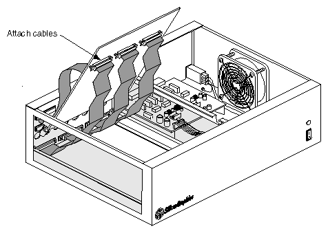
Position the SD1 board into the breakout box at an angle, with the board's BNCs somewhat aligned with the mounting holes, as shown in Figure 2-28.
Attach the ribbon cables included in the SD1 kit to the connectors on the underside of the board, as shown in Figure 2-28. These ribbon cable connectors have standoffs.
Secure each connector from the top side of the SD1 board using two 4-40 cable fastener screws (p/n 7270143) included in the SD1 kit.
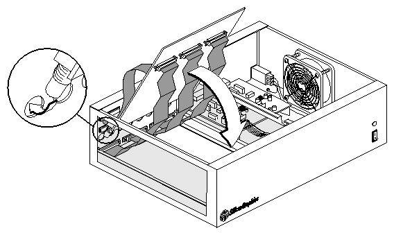
Using the handle on the SD1 board, position it: push the BNCs through the holes in the breakout box, as shown in Figure 2-29, and gently lay the board flat on top of the mounting rails.
Use the two 6-32 screws (p/n 7270805) provided in the kit to screw down the SD1 board at the front of the breakout box. Secure all eight serial BNCs with BNC lock washers and locknuts at the back of the breakout box.
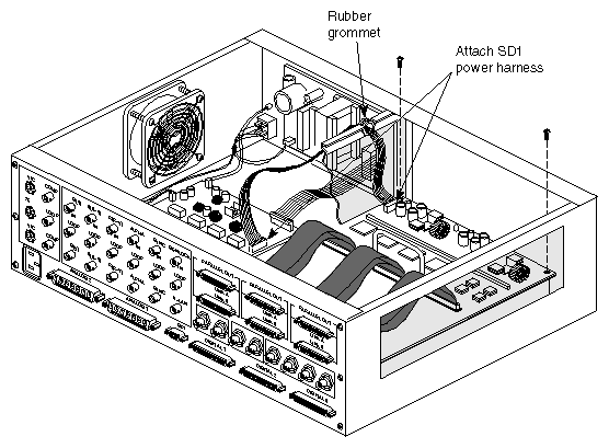
Attach the SD1 harness assembly (p/n 015-0203-001), as shown in Figure 2-30:
Insert one end of the power harness connector into the eight-pin header (H5B2) on the SD1 board.
Insert the other end of the power harness into the eight-pin header (A3C0) on the RYE1 board (on the other side of the breakout box).
Seat the rubber grommet on the power harness into the notch in the divider wall, as shown in Figure 2-30.
Replace the cover on the breakout box.
This section discusses the following parts:
label sheet (p/n 024-0840-001)
two analog video cables: 15-foot (018-0470-001) or optional 30-foot cables, ordered separately (018-0410-002)
three digital video cables: 15-foot (p/n 018-0420-002) or optional 30-foot cables, ordered separately (018-0431-002)
flanges (p/n 040-0766-001) and screws (p/n 9300025) for mounting breakout box in customer's rack
To attach external cables, follow these steps:
| Caution: You must connect all internal and external Sirius Video cables, even if the customer uses digital mode only. |
Attach labels from the label sheet to all external cables.
Attach one end of an analog video cable to the ANALOG 1 connector on the I/O door. Attach the other end to the ANALOG 1 connector on the breakout box. The two ends are identical.
Note: This connector is the rightmost analog connector on the breakout box. Attach one end of the other analog video cable to the ANALOG 2 connector on the I/O door. Attach the other end to the ANALOG 2 connector on the breakout box.
Attach one end of a digital video cable to the DIGITAL 1 connector on the I/O door. Attach the other end to the DIGITAL 1 connector on the breakout box. The two ends are identical.
Connect the DIGITAL 2 and DIGITAL 3 cables in a similar fashion.
If the customer desires, mount the breakout box in the customer's rack, using the flanges and screws included in the breakout box hardware kit. The breakout box can be mounted with its panel facing either direction, as shown in Figure 2-31.
If necessary, remove the plastic feet on the bottom of the breakout box to provide clearance for other equipment.
If the customer wants the breakout box placed on top of an Onyx, swap two of the feet on the breakout box for the two taller feet included in the breakout box hardware kit, as shown in Figure 2-32.
Connect the breakout box power cord to a proper power outlet.
Caution: Always connect the breakout box to a power outlet on the same circuit as the workstation. This helps prevent ground loops, which can cause vertical hum bars in the video display. Use the breakout box power cord provided in the Sirius Video destination kit for the region or country you are in. The breakout box automatically senses and autoranges to any voltage between 100 and 240 VAC, and operates at frequencies between 50 Hz and 60 Hz. Do not connect the breakout box to power sources outside these limits.
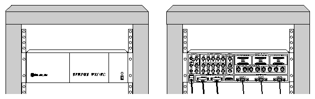
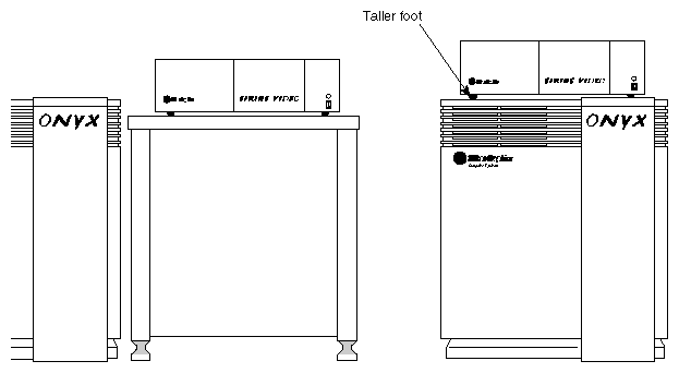
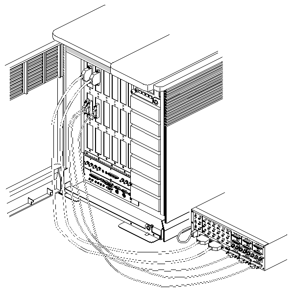
Figure 2-33 shows the Sirius Video external cables attached.
| Caution: It is recommended that you do not attach the customer's equipment to the breakout box. Appendix C, "Setting Up Sirius Video for Your Video Hardware" in the Sirius Video Programming and Configuration Guide contains instructions for the user in hooking up equipment and using the panel vcp to configure the board. |
In the event of breakout box power failure, check the two fuses located on the +12 V power supply, which is mounted on the inside wall of the breakout box. If fuses are blown, replace the entire breakout box; there are no field-serviceable parts inside.
After Sirius Video hardware is installed, load Sirius Video software from the CD included in the package. The system must be restarted so that it can be reconfigured for the new hardware.
Sirius Video software images are created in Inst format; thus, they require that the Inst program be used. Installation software and instructions are included with the standard Silicon Graphics software products.
To remove Sirius Video software after you have installed it, use
versions remove sirius |
When the system boots, messages concerning Sirius Video appear on the console and in /usr/adm/SYSLOG. This message gives the board unit number, hardware revision, address (ignore all but the lower sixteen bits), interrupt level, and interrupt vector:
Sirius: board 0 rev 4:xxx at address 0xd8813000 pri 5 vec 1 |
If a board is expected, but not found, this message appears:
Sirius: bus 0 addr 0xd8813000 not found |
This message normally appears only if you remove a board. If you do, the kernel should automatically reconfigure itself, so this message will not appear the next time you reboot.
To test whether the installation was successful, run basic system tests:
Run hinv. Output should report the presence of a Sirius Video board; for example:
Sirius video: unit 0 rev 4 at 0xd881300
Sirius video: unit 0 revision 4 on bus 0 with no options
Sirius video: unit 0 revision 4 on bus 0 with CPI DGI options
Sirius video: unit 0 revision 4 on bus 0 with CPI DGI BOB options
Sirius video: unit 0 revision 4 on bus 0 with CPI DGI BOB SD1 options
where
unit is a sequential number of all the boards found
revision is the hardware revision level
bus is the bus adapter number (usually 0, 36, or 37)
CPI means that the connection to the GE8/GE10/GE10V board is present
If CPI is not recognized, make sure that the cable (018-0423-002) that connects the VO2 and the GE8/10 is inserted into the proper location on the VO2 board and there are no bent pins. If MCO is installed, the address of VO2 must be 0x3800 or above in order for this cable to be seen.
DGI means connection to the DG2 board via the PAB is present.
If DGI is not recognized:
– Check for bent pins on the PAB1 or on the connector on the DG2 board.
– Make sure cables 018-0421-002 and 018-0422-002 are installed.
– If MCO is installed on the same graphics pipe, DGI is not seen.
BOB means the breakout box is present, correctly connected, and powered on.
If the breakout box is not recognized:,
– Make sure the internal and external analog cables (ANALOG 1 and ANALOG 2) are connected properly. If ANALOG 1 and ANALOG 2 are reversed, the breakout box is not seen.
– Make sure the breakout box is powered on when the system is booted, not after system boot.
SD1 means the serializer/deserializer option is installed in the BOB.
If you boot the system with the breakout box disconnected or not powered on, you must reboot for the system to recognize it.
Test input and output:
Loop inputs and outputs together on the breakout box.
Call up the panel:
/usr/sbin/vcp
From the Utilities menu, select "Live Video Output." The Live Video Output white rectangle appears on the workstation monitor, as well as a white rectangle in the upper left corner that encloses data that is output. Verify that the contents of the Live Video Output window match those of the rectangle in the upper left corner.
From the Utilities menu, select "Live Video Input." The Live Video Input window appears on the monitor. Verify that the contents of the Live Video Input window match those of the Live Video Output window.
Run
/usr/dmedia/bin/SIRIUS/vidtovid
This program takes CCIR601 input and routes it to output. Check output on the low-resolution monitor.
It is strongly recommended that non-standard installations be changed to fit the standard model; otherwise, the system file editing explained in this section will have to be redone every time new software is installed.
To support non-standard setups, edit (as root) the file /var/sysgen/system/video.sm. This file describes every place a Sirius board can appear. Extra entries are not harmful; if you make changes to this file, add new entries instead of changing existing ones. When the kernel is autoconfig'ed, the system uses this file to determine whether Sirius boards are present or not. This information is used only at kernel configuration time; if you change this file, you must configure a new kernel, and then boot that kernel for the changes to take effect.
Typical file contents are shown below. Entries in the file are actually on one line; they are expanded here for clarity.
Onyx/Challenge:
   VECTOR: module=vo2
           bustype=VME
           adapter=0
           ctlr=0
           ipl=5
           iospace=(A16NP,0x3000,0x100)
           exprobe_space=(r,A16NP,0x3000,4,0x00bcdef0,0x00ffffff)
MP bus:
   VECTOR: module=vo2
           bustype=VME
           adapter=0
           ctlr=0
           ipl=5
           iospace=(A16NP,0xb7c03000,0x100)
exprobe_space=(r,A16NP,0xb7c03000,4,0x00bcdef0,0x00ffffff) |
The VECTOR variables are as follows.
| module | Board name; it must be vo2. | |
| bustype | Must be VME. | |
| adapter | Designates the VME bus; it must be 0 for the main VME bus in an Onyx or Challenge system, and for all MP bus systems. For CC3 VME buses 1 and 2, it is normally 36 and 37. | |
| ctlr | Consists of several components:
If the system finds a board when it probes for one, it skips all other entries with the same ctlr number. Normally, all entries in the file should have unique ctlr fields, unless you are making a base address change, where the board will not be at the standard address. | |
| ipl | Interrupt level, normally 5. | |
| iospace | Where the board lives (A16NP VMEbus space), with a certain base address and a certain length (always 0x100). The space must always be A16NP; the base address can be changed. | |
Note the difference between Onyx and MPbus address entries: a non-standard board switch setting of 0x90, for instance, would be expressed as iospace=(A16NP,0x9000,0x100) on Onyx and Challenge systems, and as iospace=(A16NP,0xb7c09000,0x100) on MPbus. | ||
| exprobe_space | Where to look for the board at autoconfig time. This is very much like iospace and must be changed in exactly the same way. If the iospace and exprobe_space entries do not match, the system will not operate correctly. | |
For a switch setting of 0x90, for instance, you would use exprobe_space= (r,A16NP,0x9000,4,0x00bcdef0,0x00ffffff) or (r,A16NP,0xb7c09000,4,0x00bcdef0,0x00ffffff). |
After changing this file, and with a Sirius board installed to match your changes, you may wish to run autoconfig with the -v option. Messages tell you which boards were found and which were not. This message means the board was found:
exprobe spaced vo2 adapter 0 |
This message means the board was not found:
vo2, adapter 0 exprobe space failed |
If Multi-Channel Option is already installed in the system into which you have installed Sirius Video and both options are on the same VME bus, follow these steps:
If you are installing Sirius Video in a system that has the I/O panel version (no breakout box) of Multi-Channel Option, you might have to move MCO panels; see Section 2.2, "Installing the Sirius Video Panels in the I/O Door," earlier in this chapter.
Make sure you have reset DIP switches on the Sirius Video board for use in a system with the Multi-Channel Option installed. See Table 2-3 and Table 2-5 in Section 2.3, "Verifying or Changing the Physical VME Address on the Board," earlier in this chapter.
If you are using a nonstandard VME address for Sirius Video, edit the file /var/sysgen/system/video.sm, as explained in Section 2.13, "Editing the System File for Nonstandard Setups," earlier in this chapter. Specifically, add 128 to ctlr, as well as an arbitrary number between 0 and 15 to make the entry unique.
hinv output should report the presence of a Sirius Video board; for example:
Sirius video: unit 0 revision 4 on bus 0 with CPI BOB options
where CPI means that the system recognizes the TO GFX cable (GPI-80 input to graphics) (p/n 018-0423-002) between the VO2 (MCO) and GE8 (GE10) boards. The system detects this cable only if the VME address on the VO2 board has been changed as specified in the Multi-Channel Option Installation Instructions, or if the system detects the microstrip cables for the MCO.
Note: With MCO installed, the RealityEngine cannot send information to Sirius Video. Therefore, Sirius cannot output graphics as video, either directly or pixel averaged. The capabilities of the Multi-Channel Option, however, are not affected.