This chapter explains how to use board functionality tests for Sirius Video.
Major functional areas of the Sirius Video board convert live graphics pixel streams to video. Figure 3-1 is a block diagram of how the Sirius Video board (VO2) interacts with other workstation components.
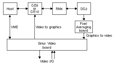
As shown in Figure 3-1, the Sirius Video board communicates
with the workstation through the VME bus
with the graphics board through the Graphics Peripheral Interface (GPI)
with the DG2 through the Pixel Averager Board (PAB1) and the DVI
Data from graphics comes to the VO2 board via the PAB1 (back door), as well as through the VME bus. The paddleboard is unidirectional (from graphics to VO2).
Figure 3-2 diagrams Sirius Video board functionality.
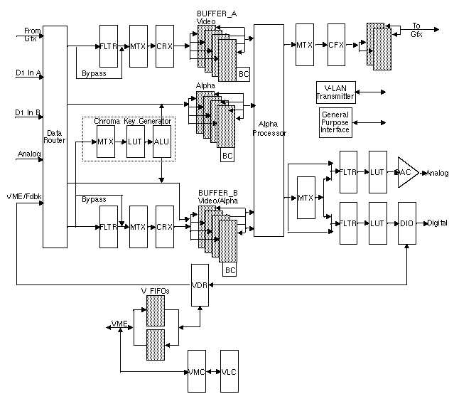
For details on board functional components, see the Sirius Video Programming and Configuration Guide (007-2238-00x).
Functionality feedback tests check
pixel averager
VME bus communication
D1 output and input
In addition, VME feedback tests that check data flow through the board can be used as quick functionality tests.
The graphics-based functionality feedback test executables route a pattern through the specified board component and buffer (A or B) to output, and compare the test pattern with the output.
The tests are as follows:
vo2PAtoCP tests pixel averager functionality by routing a test pattern through pixel averager and out to graphics, and verifying the pattern.
vo2VMEtoCP tests VME-board communication by routing the test pattern into the Sirius Video VME input through the board and out to graphics, and verifying the pattern.
vo2D1toCP checks digital-video-to-graphics and graphics-to-digital-video capabilities by drawing a pattern into the buffer, looping it through the D1 connector, and verifying the pattern.
vo2VMEtoCKGtoCP tests the color key generator (CKG) by routing a test pattern via the VME bus through the CP (graphics) and running an algorithm check (as does the CKG) to see if the value of alpha is the maximum among the values for R, G, and B, for each pixel in the output window. If alpha is not the maximum value for a particular pixel, the test prints the pixel coordinates and the values for R, G, B, and alpha.

Note: This functionality feedback test displays only one window, not the three windows shown in Figure 3-3.
These tests execute pixel-by-pixel comparisons. If failure occurs at any pixel, the test prints the pixel location, the expected value, and the received value. Test failure messages are displayed in 12-bit space.
This section discusses
test output windows
syntax
using the vo2D1toCP test
The functionality feedback tests display three windows, as shown in Figure 3-3:
test pattern window, which shows the test pattern being sent
errors window, which shows the color of any gun(s) that failed the test
output window, which shows the test pattern being read
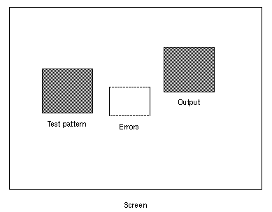
| Note: The vo2VMEtoCKGtoCP functionality feedback test does not display the three windows shown in Figure 3-3, only the output window. |
In 625 mode, the windows overlap, and no comparison takes place.
The function prototype for all the functionality feedback tests is
testname -a -b[Buffer Channel] [-f Format] [-c RGBColor] [-p TestPattern] [-s Smooth Select] |
Variables are as follows.
| Buffer Channel |
| |||
| Format | Either 0 (serial) or 1 (parallel). | |||
| RGBcolor | One of the following:
| |||
| TestPattern | Operates in 12-bit space, and indicates errors in 8-bit space (MSB), except for test 40; this test uses 10 of the 12 bits and is one of the following:
| |||
| Smooth Select | Integer from 0 (no smoothing) through 7 (greatest amount of smoothing). |
In additional to these parameters, vo2D1toCP can use -d1 or -d2 to indicate channel 1 or 2, respectively.
| Note: Default timing for the tests is 525. It is not advisable to run any test in 625 mode, because the test pattern and output windows are so big that they overlap, which causes the compare process to fail. |
The following example runs the SMPTE color bars through serial D1 channel 1 to the pixel averager, into buffer A, and out to the screen, at 525 lines per frame:
vo2PAtoCP -a -b A -p 23 |
The following example runs the color magenta through serial D1 channel 1 to the VME input, into buffer B, and out to the screen, at 525 lines per frame:
vo2VMEtoCP -a -b B -f 1 |
To use the vo2D1toCP test, follow these steps:
Attach the D1 digital parallel loopback connector to the D1 on the Sirius Video breakout box.
Get into the /SIRIUS/dmedia/diags/ directory. At the IRIX prompt, enter
vo2D1toCP [parameters]
| Note: For this test, use test patterns 20 and 23 only; use -d1 and -d2 to indicate channel. |
The tests vo2D1toCP and vo2D1toCP have an additional parameter, -x number, that specifies texture mode. number specifies the texture mode:
4 for 4-bit texture mode
5 for 5-bit texture mode
8 for 8-bit texture mode
For texture mode, only test pattern 30 (linear ramp) can be used; other test patterns cause failure.
This example specifies 4-bit texture mode, with white for the test pattern:
vo2VMEtoCP -x 4 -p 30 -c 1 |