This chapter describes the procedure for upgrading an existing Indigo2 or
CHALLENGE M to a POWER Indigo2 or POWER CHALLENGE M.
The basic steps to upgrade the system are:
Verify that the customer's system has been backed up.
Verify that you have all of the required components before proceeding with the installation. See Section 2.2, "Checking the Kit Contents."
Power off the system, move the customer's SIMMs from the old IP22 board to the new IP26 board, then remove the power supply, CPU module, and IP22 base board. (For Indigo2 systems, you also remove the audio subsystem from the IP22 base board and install it on the new, IP26 base board.) See Section 2.3, "Removing the Old Components."
Install the upgrade components (power supply, R8000 CPU module, and IP26 base board). See Section 2.4, "Installing the New Components."
Power on the system, enter the Command Monitor, and verify the new configuration using the hinv command. See Section 2.5, "Testing the Installation."
Boot the IRIX 6.0.1 miniroot from CD-ROM and install IRIX. See Section 2.6, "Software Installation."
Attach the upgrade "Power" emblem to the front of the system and the upgrade identification label to the back of the system. See Section 2.7, "Completing the Installation."
Pack and return the old components. See Chapter 3, "Returning the Old Components."
Be sure to read the safety guidelines outlined in this section before proceeding with the installation procedures.
Follow these ESD-preventive measures:
Connect a ground strap to your wrist when installing and removing peripherals.
Be sure that you and all of the electrical equipment that you handle during this installation remain at a ground potential of zero to avoid damage from ESD.
Remove a component from its antistatic bag only when you are properly grounded with a ground strap, and only when you are working on the board or installing it.
Do not use an ohmmeter on the R8000 CPU module.
 | Warning: Use extreme care when handling the R8000 CPU module and attached flex cable. Do not set the board down roughly onto a hard surface (such as a desktop or filing cabinet) and be careful not to scrape the underside of the board against parts of the system chassis. The CPU module has several capacitors mounted on the back side that help control various internal clocks, and if any one of these capacitors is damaged the CPU module will not function properly. |
Because of the size of the R8000 CPU module, SIMMs in Bank C (SIMMs S8 through S12) and the last SIMM in Bank B (SIMM S7) on the IP26 base board cannotbe taller than
1.27 inches (approximately 32 mm). Figure 2-1 shows the SIMM sockets that are affected by this height limitation
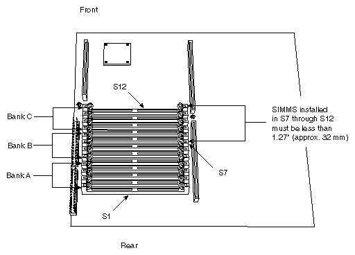
SIMMs in Bank A and SIMMS in sockets SS5 through S6 in Bank B can be taller than
1.27 inches (approximately 32 mm).
| Warning: Never install a SIMM in Bank C or in the last socket of Bank B (S7) if it is taller than 1.27 inches (approximately 32 mm). SIMMs that are too tall can damage the R8000 CPU module if they are installed in these particular sockets. |
For more information about memory in the POWER Indigo2 and POWER CHALLENGE M, see Section 1.6, "Maximum Memory (SIMM) Configurations."
This section lists the major contents of the upgrade kit:
IP26 board (system base board)
R8000 CPU module with attached flex cable
power supply (Rev S or later; marked on side of power supply)
screws (Phillips), four 8 mm (M3 thread) and one 30 mm (M3 thread)
insulating sheet (for the R8000 CPU module)
SIMM removal tool
IRIX 6.0.1 (or later) CD-ROM
POWER upgrade badge
upgrade label (to attach to the back of the system)
shipping box in which to pack the old components
RMA labels for old components
You need the following tools:
#2 Phillips screwdriver
SIMM tool (provided in upgrade kit)
wrist strap
You should also make sure that a CD-ROM drive is available, preferably one that is attached directly to the system (either internally or externally).
Remove the old components from the customer's Indigo2 and CHALLENGE M as follows:
Shut down the system and turn the power switch off.
Disconnect all external cables from the system, including the power cable.
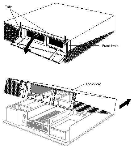
Open the top cover, as shown in Figure 2-2.
If there is a peripheral installed in the 5-1/4 inch drive tray, remove it now. As a precaution, you may wish to remove any peripherals from the 3-1/2 inch drive bay to prevent damage from shock and vibration while you perform the upgrade. However, this is not strictly required.
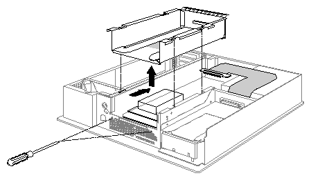
Disconnect the flex cable from the 5-1/4 inch drive tray, then loosen the captive screws at the front of the system and remove the drive tray. Slide the tray back to unlatch it, then lift it from the system, as shown in Figure 2-3.
Remove the new IP26 system base board from its anti-static packaging and place it on a flat, antistatic surface.
Remove all of the customer's SIMMs from the system and reinstall them on the new IP26 board.
We recommend that you start populating the SIMM sockets on the IP26 board at Bank C (closest to the front of the system). This bank will be covered by the new R8000 CPU module and it will be difficult for the customer to install new memory into this bank in the future. Also, see Section 2.1.2, "SIMM Height Limitation" for a description of the maximum height for SIMMs in various banks on the IP26 board.
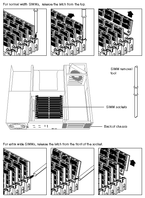
Figure 2-4 shows how to use the SIMM removal tool to unlatch a SIMM from its socket. Tilt the SIMM backwards, then lift it out of the socket. To install a SIMM, set it into the socket at the same angle at which you removed it. Press firmly to seat the SIMM, then tilt the SIMM upright until it latches.
Some high-capacity SIMMs may extend over the top of the SIMM release latches. In this case, you must unlatch the SIMMs using the front part of the SIMM release latches. Figure 2-4 shows both methods. Also, you must start at the rear-most SIMM socket (lowest SIMM socket number) at the back of the chassis and work towards the front of the system (highest SIMM socket number), removing the SIMMs sequentially.
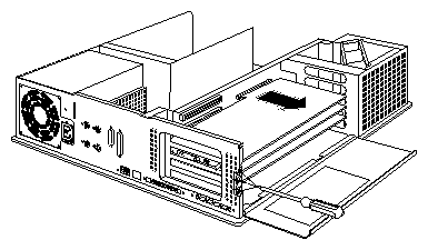
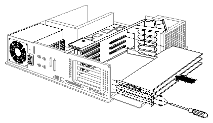
Lower the metal door that covers the GIO and EISA expansion slots, then unfasten the screws that hold the graphics boards in place (for an Indigo2) and remove the boards. If there are any EISA boards installed, remove them also. Figure 2-5 shows how to remove the graphics boards; EISA boards are removed in a similar manner.
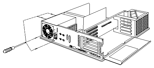
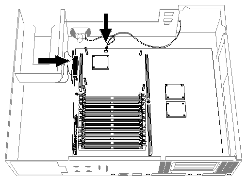
Unfasten the four screws that hold the power supply in place. Two are located on the back of the system and the other two are located on the side of the system, as shown in Figure 2-6.
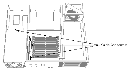
Disconnect the power supply cables, as shown in Figure 2-7.
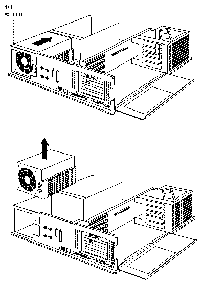
Slide the power supply forward about 1/4 inch (approximately 6 mm), then lift it out of the chassis, as shown in Figure 2-8.
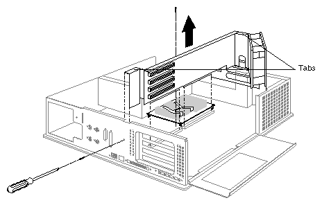
Remove the two screws that fasten the EISA/GIObus backplane to the chassis, as shown in Figure 2-9. Pull the backplane straight up out of the system. Pull on the metal tabs indicated in Figure 2-9.

Note: Some older chassis may not have screws fastening the backplane to the chassis. Disconnect the speaker and power-switch wires, and the SCSI cable from the IP22 base board. See Figure 2-10.
Remove the screws that fasten the IP22 base board to the system chassis. There are five screws on the back of the chassis, and two screws on the base board, as shown in Figure 2-11.
If there is an audio subsystem board attached to the IP22 base board, remove it and attach it to the new IP26 base board.
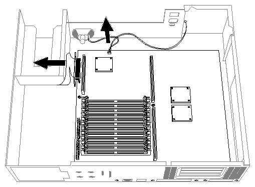
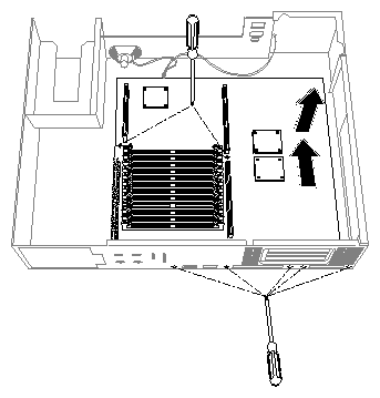
You are finished removing the old components of the system. Proceed with Section 2.4, "Installing the New Components."
Install the new components as follows.
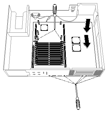
Install the IP26 base board. Place the board over the slot pins and slide the board down onto them. You may need to hold up the connectors at the back of the chassis in order to slide the board into position.
Slide the board back as far as it will go. Check to make sure all the screw holes line up, then insert and tighten all the screws, as shown in Figure 2-12.
Connect the SCSI cable and the speaker and power-switch wires to the IP26 base board, as shown in Figure 2-13.
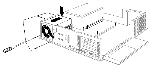
Install the new power supply and connect the power supply cables. Lower it into place, then slide it towards the back of the chassis. Align the screw holes on the power supply with the appropriate holes on the chassis, then install and tighten the screws. See Figure 2-20.
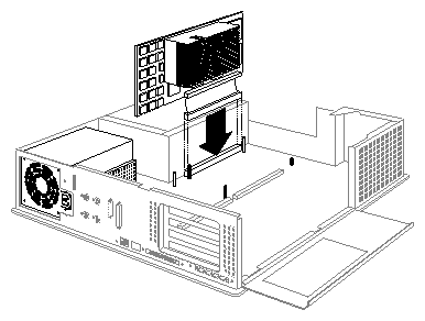
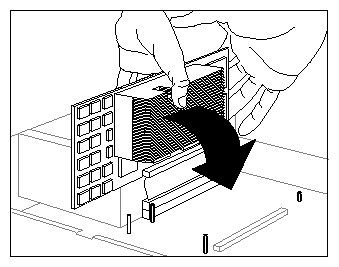
Note: With some older models of the Indigo2 and CHALLENGE M, you may have difficulty sliding the power supply into position. If this happens, remove the power supply and examine the bottom of the unit. Locate the two tabs on the bottom of the power supply that attach the unit to the U-shaped slots on the bottom of the system chassis. Using a flat-bladed screwdriver, bend the two tabs outward slightly (approximately two to three millimeters) so that they protrude further from the bottom of the power supply. This allows the tabs to slide into the U-shaped slots. Remove the R8000 CPU module from its anti-static bag and position it as shown in Figure 2-14.
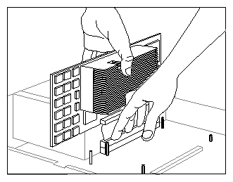
Hold the R8000 CPU module in one hand and use your other hand to seat the flex-cable connector, as shown in Figure 2-15. Apply firm, even pressure to the flex-cable connector using your fingers.
Do not place too much weight on the flex cable and do not twist or rock the CPU module on the flex cable. Bending and twisting the flex cable can damage it.
Also, be careful not to scrape or hit the R8000 CPU module against the 3-1/2 inch drive bay. There are several critical capacitors on the back of the CPU module.
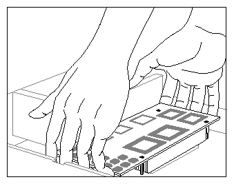
When the flex-cable connector is properly seated on the IP26 base board, prepare to lower the R8000 CPU module. Shift your hands to the front and back sides of the CPU module. Figure 2-16 shows the right hand already in position at the front of the module.
When both hands are in position, lower the module onto the standoffs, as shown in Figure 2-17. This hand position is the best to use for raising and lowering the CPU module, as it places the minimum stress on the flex cable.
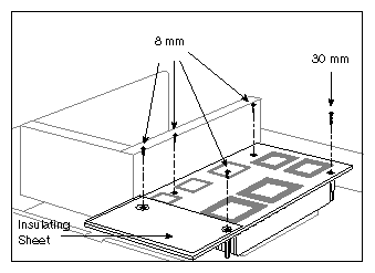
Place the insulating sheet on the R8000 CPU module as indicated in Figure 2-18. Position the sheet along the rear edge of the CPU module, and align it with the rear-most two screw holes.
Install the five Phillips screws that attach the R8000 CPU module to the standoffs, as shown in Figure 2-18. Note the location of the long, 30 mm screw. Finger-tighten the screws first, then tighten them snugly using the screwdriver.
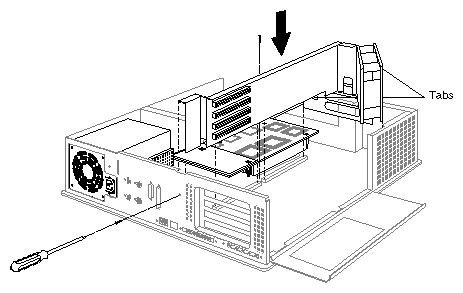
Install the backplane. Lower it into position, and press firmly to seat the backplane connectors in the slots on the IP26 base board. See Figure 2-19.
Install the graphics boards (Indigo2 only) and any EISA boards that you removed from the system. See Figure 2-21.
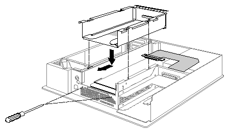
Install the 5-1/4 inch drive tray and attach the flat SCSI cable. When lowering the tray, keep it level, as shown in Figure 2-22, to avoid hitting the CPU module with a corner of the drive tray.
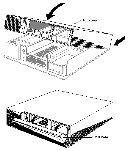
Warning: Be very careful not to damage the R8000 CPU module when installing the 5-1/4 inch drive tray. The back side of the CPU module is very close to the underside of the drive tray. Before sliding the drive tray forward and locking it in place, visually inspect the clearance between the drive tray and the CPU module. (Look through the perforated metal at the bottom of the drive tray.) Replace the top cover, as shown in Figure 2-23.
Reinstall any peripherals and reattach any cables that you removed from the system.
At this point you should make sure that a CD-ROM drive is attached to the system so that you can reinstall IRIX. Although you can use a CD-ROM drive across the network, the procedure given in this chapter assumes the CD-ROM drive is directly connected to the system. It can be either an internal or external CD-ROM drive.
You are finished installing hardware. Turn to Section 2.5, "Testing the Installation."
Follow this procedure to verify that you installed the upgrade correctly and that the components are working properly:
Power on the system.
Indigo2 only: Press <Esc> to enter the System Maintenance Menu (CHALLENGE M stops automatically at this menu).
From the System Maintenance Menu, enter the Command Monitor.
At the Command Monitor prompt (>>), type
hinv -v
You should see a display similar to the following:
System: IP26 Processor: 75 Mhz R8000Primary I-cache size: 16 KbytesPrimary D-cache size: 16 KbytesSecondary cache size: 2 Mbytes Memory size: 64 Mbytes SCSI Disk: scsi(0)disk(1)
After you are satisfied that the board is recognized by hinv and the system is running normally, type exit to quit the Command Monitor.
Do not allow the system to boot. Instead, reenter the System Maintenance Menu. (For Indigo2 systems, press <Esc>.)
You are now ready to boot the miniroot and install IRIX 6.0.1. Turn to Section 2.6, "Software Installation."
The next step in the upgrade procedure is to install IRIX 6.0.1. You must perform this installation from the miniroot.
Follow these steps to boot the miniroot and install IRIX 6.0.1:
Make sure a CD-ROM drive is attached to the system (or is available on the network). This procedure assumes you have a CD-ROM drive attached directly to the system. If you have to use a CD-ROM drive across the network, see the IRIS Software Installation Guide for information on booting the miniroot from a remote CD-ROM.
Load the IRIX 6.0.1 CD into the CD-ROM drive.
At the System Maintenance Menu, select option 2, Install System Software.
Indigo2 only: You see a series of icons representing installation choices. Select the icon for the installation you are performing, for example Local CD-ROM. The miniroot begins to load. Proceed with the next step.
CHALLENGE M only: You are prompted for an appropriate installation source, for example:
Load software from local CD-ROM? (y/n) [y]
Press <Enter> to boot the miniroot from the CD-ROM drive.
After a while, you see the inst prompt. A default set of subsystems is selected for installation. You may wish to add or delete subsystems depending upon your customer's needs.
After you have selected the appropriate subsystems, enter go at the inst prompt.
Once all the subsystems are installed, enter quit to exit from Inst.
Reboot the system to multiuser mode.
Log in and enter the following command to verify that the installation worked and that the operating system is IRIX 6.0.1:
uname -a
If uname reports that the system is running IRIX 6.0.1, the installation is successful.
You can now complete the installation. See the next section, Section 2.7, "Completing the Installation."
There are two final steps to complete the upgrade:
Attach the "POWER" badge to the front of the system. It snaps into the front grill.
Install the upgrade label that indicates the new Silicon Graphics model number of the system. Affix the label at the rear of the system, covering part of the old label.
You are now ready to pack the old components for return shipment to Silicon Graphics. Turn to Chapter 3, "Returning the Old Components."