This chapter contains marketing codes, illustrations, and parts lists for CHALLENGE and Onyx rack systems. Parts common to both rack and deskside units are illustrated in later chapters.
Tables 1-1 through 1-4 list the marketing codes for CHALLENGE and Onyx rack systems.
Table 1-1. POWER CHALLENGE Rack System Marketing Codes and Descriptions
Marketing Code | Description |
|---|---|
POWER CHALLENGE XL Rack Server, 2x75 MHz R8000, 64MB mem, 1 Interleaved Memory Board, 2GB Sys Disk | |
POWER CHALLENGE XL Rack Server, 4x75 MHz R8000, 64MB mem, 1 Interleaved Memory Board, 2GB Sys Disk | |
POWER CHALLENGE XL Rack Server, 8x75 MHz R8000, 64MB mem, 1 Interleaved Memory Board, 2GB Sys Disk | |
POWER CHALLENGE XL Rack Server, 12x75 MHz R8000, 64MB mem, 1 Interleaved Memory Board, 2GB Sys Disk | |
POWER CHALLENGE XL Rack Server, 16x75 MHz R8000, 64MB mem, 1 Interleaved Memory Board, 2GB Sys Disk | |
POWER CHALLENGE XL Rack Server, 18x75 MHz R8000, 64MB mem, 1 Interleaved Memory Board, 2GB Sys Disk | |
POWER CHALLENGEarray, (4) 8x75 MHz R8000 XLs w/ 1GB mem 4-way, 10GB Disk - Contact SSD Marketing |
Table 1-2. CHALLENGE Rack System Marketing Codes and Descriptions
Marketing Code | Description |
|---|---|
R-48802-S4 | CHALLENGE XL Rack Server, 2x200 MHz R4400 w/4MB secondary cache, 64MB memory, 1 Interleaved Memory Board, 2GB Sys Disk |
R-48804-S4 | CHALLENGE XL Rack Server, 4x200 MHz R4400 w/4MB secondary cache, 64MB memory, 1 Interleaved Memory Board, 2GB Sys Disk |
R-48808-S4 | CHALLENGE XL Rack Server, 8x200 MHz R4400 w/4MB secondary cache, 64MB memory, 1 Interleaved Memory Board, 2GB Sys Disk |
R-48816-S4 | CHALLENGE XL Rack Server, 16x200 MHz R4400 w/4MB secondary cache, 64MB memory, 1 Interleaved Memory Board, 2GB Sys Disk |
R-48836-S4 | CHALLENGE XL Rack Server, 36x200 MHz R4400 w/4MB secondary cache, 64MB memory, 1 Interleaved Memory Board, 2GB Sys Disk |
CHALLENGE XL Rack Server, 2x150 MHz R4400, 64MB memory, 1 Interleaved Memory Board, 2GB Sys Disk | |
CHALLENGE XL Rack Server 4x150 MHz R4400, 64 MB memory, 1 Interleaved Memory Board, 2GB Sys Disk | |
CHALLENGE XL Rack Server, 8x150 MHz R4400, 64 MB memory, 1 Interleaved Memory Board, 2GB Sys Disk | |
CHALLENGE XL Rack Server, 16x150 MHz R4400, 64MB memory, 1 Interleaved Memory Board, 2GB Sys Disk | |
CHALLENGE XL Rack Server, 24x150 MHz R4400, 64MB memory, 1 Interleaved Memory Board, 2GB Sys Disk | |
CHALLENGE XL Rack Server, 36x150 MHz R4400, 64MB memory, 1 Interleaved Memory Board, 2GB Sys Disk |
Table 1-3. POWER Onyx Rack System Marketing Codes and Descriptions
Marketing Code | Description |
|---|---|
POWER Onyx RE2 Rack, 4MB texture memory, 2x75MHz R8000, 64MB memory, 1 Interleaved Memory Board, 2GB system disk | |
POWER Onyx RE2 Rack, 16MB texture memory, 2x75MHz R8000, 64MB memory, 1 Interleaved Memory Board, 2GB system disk | |
POWER Onyx RE2 Rack, 4MB texture memory, 12x75MHz R8000, 64MB memory, 1 Interleaved Memory Board, 2GB system disk |
Table 1-4. Onyx Rack System Marketing Codes and Descriptions
Marketing Code | Description |
|---|---|
Onyx RealityEngine2™ Rack, 4MB texture memory, 2x150 MHz R4400™, 64MB memory, 1 Interleaved Memory Board, 2GB system disk | |
Onyx RealityEngine2 Rack, 4MB texture memory, 4x150 MHz R4400, 64MB memory, 1 Interleaved Memory Board, 2GB system disk | |
Onyx RealityEngine2 Rack, 4MB Texture Memory, 8x150 MHz R4400, 64MB memory, 1 Interleaved Memory Board, 2GB system disk | |
Onyx RealityEngine2 Rack, 4MB Texture Memory, 16x150 MHz R4400, 64MB memory, 1 Interleaved Memory Board, 2GB system disk | |
Onyx RealityEngine2 Rack, 4MB Texture Memory, 24x150 MHz R4400, 64MB memory, 1 Interleaved Memory Board, 2GB system disk | |
Onyx RealityEngine2 Rack, 4MB texture memory, 2x150 MHz R4400, 64MB memory, 1 Interleaved Memory Board, 2GB system disk | |
Onyx RealityEngine2 Rack, 4MB texture memory, 4x150 MHz R4400, 64MB memory, 1 Interleaved Memory Board, 2GB system disk | |
Onyx RealityEngine2 Rack, 4MB Texture Memory, 8x150 MHz R4400, 64MB memory, 1 Interleaved Memory Board, 2GB system disk | |
R-45816-RE | Onyx RealityEngine2 Rack, 4MB Texture Memory, 16x150 MHz R4400, 64MB memory, 1 Interleaved Memory Board, 2GB system disk |
R-45824-RE | Onyx RealityEngine2 Rack, 4MB Texture Memory, 24x150 MHz R4400, 64MB memory, 1 Interleaved Memory Board, 2GB system disk |
R-45802-RERM5 | ONYX RealityEngine2 Rack, 16MB Texture Memory, 2x150MHz R4400, 64MB memory, 1 Interleaved Memory Board, 2GB system disk |
R-45804-RERM5 | ONYX RealityEngine2 Rack, 16MB Texture Memory, 4x150MHz R4400, 64MB memory, 1 Interleaved Memory Board, 2GB system disk |
The rack part diagrams include:
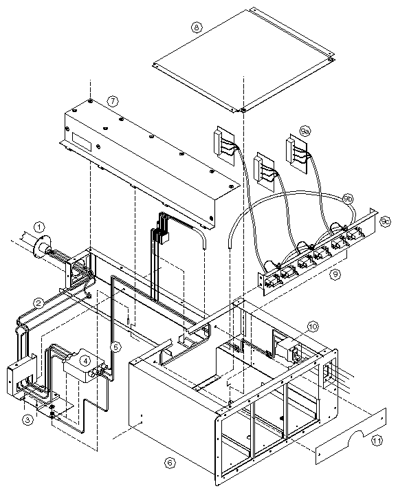
Rack Assemblies (Figure 1-1)
Chassis overviews:
Rack chassis, frame and skin assemblies (Section 1.2.1.1)
Rack chassis, front-right view (Section 1.2.1.2)
Rack chassis, front-left view (Section 1.2.1.3)
Rack chassis, rear-left view (Section 1.2.1.4)
SCSIBox2 assembly (Section 1.2.2)
Power tray assemblies:
Power tray assembly, North American (Section 1.2.3.1)
CC3 Power tray assembly, 208V North American (Section 1.2.3.2)
CC3 Power tray assembly, 400V International (Section 1.2.3.3)
For details on components common to rack and deskside units, see Chapter 3. For details on board assemblies, see Chapter 4. For details on media assemblies, see Chapter 5. For details on selected CHALLENGE/Onyx options, see Chapter 6.
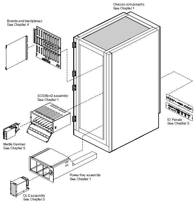
This section describes various overviews of the rack chassis.
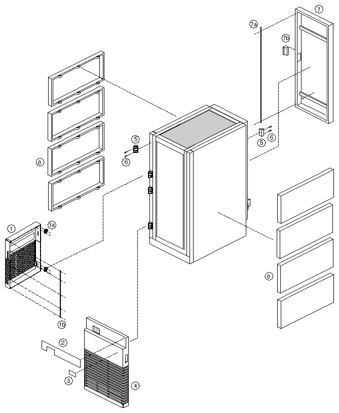
For a description of rack chassis frame and skin components, see Figure 1-2 and Table 1-5.
Table 1-5. Rack Chassis Frame and Skin Assemblies
ID | Description | SGI Part # | Chal | Onyx |
|---|---|---|---|---|
1
1a 1b | UPPER FRONT DOOR ASSY CHAL RACK [blue] DOOR ASSY UPPER FRONT [black] HINGE BLOCK SLIP PIN CASTING MAGNETIC STRIP | X
X X |
X X X | |
2 | MAIN CHALLENGE LABEL MAIN ONYX LABEL | X |
X | |
3 | XL LABEL VTX LABEL RE2 LABEL | X |
X X | |
4 | LOWER FR DOOR ASSY CHAL RACK [blue] DOOR ASSY LOWER FRONT [black] | X |
X | |
5 | HINGE BLOCK FRAME CASTING [4 used front, 2 used on back] | X | X | |
6 | SCREW 10-32X1/2" SCH CAP ALLEN DR [2 used per hinge] | X | X | |
7 7a 7b | REAR DOOR ASSY CABINET [Metal] MAGNETIC STRIP HANDLE 5.40 X 1.40 POCKET FULL | X X X | X X X | |
8 | PANEL SIDE RACK [4 used on left, 4 used on right (same part)] | X | X | |
| TAPE ADH FOAM DBL CTD [Not shown, used on doors by the foot] | X | X | |
| FOAM URETHANE [Not shown, used on doors by the foot] | X | X |
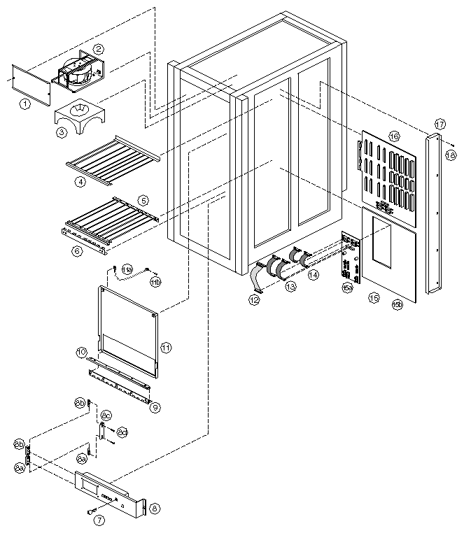
For a description of components seen in the rack chassis front-right view, see Figure 1-3 and Table 1-6.
 | Note: "CC1" means "Card Cage 1" [top front of system, behind status panel]. |
Table 1-6. Components Shown in Rack Chassis Front-Right View
ID | Description | SGI Part # | Chal | Onyx |
|---|---|---|---|---|
1 | PANEL ACCESS FAN TRAY | X | X | |
2 | BLOWER ASSY 11" RACK -TR [2 used, front & rear are the same] | X | X | |
3 | DIRECTOR UPPER AIR CARD CAGE | X | X | |
4 | CARD GUIDE ASSY CC1 TOP GRFX CARD GUIDE ASSY TOP CC1 -TR | * X | X | |
5 | CARD GUIDE ASSY CC1 LOWER GRFX CARD GUIDE ASSY BOTTOM CC1 -TR | * X | X | |
6 | BOARD LOCK ASSY TERM CC1 GRAPHICS BOARD LOCK ASSY TERM CC1 SERVER | * X | X | |
7 | KEY [C&K brand, A126 cut] | X | X | |
8 8a 8b 8c 8d | STATUS PANEL DISPLAY ASSY -TR HINGE OFFSET RIGHT HAND #10-32 [2 pieces: pin & receptacle] HINGE OFFSET LEFT HAND #10-32 [2 pieces: pin & receptacle] MTG BRKT FRONT DISPLAY PANEL SCREW 10-32X1/2" SCH CAP ALLEN DR | X X X X X | X X X X X | |
9 | HINGE | X | X | |
10 | EMI GASKET | X | X | |
11 11a 11b | CC1 CPU DOOR CABLE RETAINING [Two cables included with item 11] SCREW 6-32X3/8 PNH PHH STL ZINC [2 per cable, 4 per system] | X X X | X X X | |
12 | CBL ASSY SYS CNTR BKPLN2 | X | X | |
13 | CABLE ASSY POWER JUMPER 8.46"L [2 used per system] | X | X | |
14 | CBL ASSY PWR JUMPER 7.46"L [2 used per system] | X | X | |
15 15a 15b | CC3 POWER BOARD ASSY [Board, frame, and screws] PCA CC3 PWR JUMPER [Board only, has inlet temperature sensor] ADAPTOR CC POWER JUMPER [metal frame only] | X X X | X X X | |
16 | PCA MIDPLANE GRAPHICS [shown] PCA TERM GFX 3.3/5V BP [Kona-ready - not shown] PCA TERM SERVER BP TESTED [not shown] | * * X | X X | |
17 | MIDPLANE ACCESS PANEL | X | X | |
18 | SCREW 6-32X1/4LG T-TITE PNH PHH ZN [10 used] | X | X |
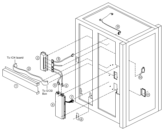
For a description of components seen in the rack chassis front-left view, see Figure 1-4 and Table 1-7.
Table 1-7. Components Shown in Rack Chassis Front-Left View
ID | Description | SGI Part # | Chal | Onyx |
|---|---|---|---|---|
1 | COVER EXTERNAL HORIZ SCSI | X | X | |
2 | CBL ASSY (IO4-SCSI BOX) -TR [Part number includes 2 cables (as shown). Each system uses 4 cables.] | X | X | |
3 | COVER EXTERNAL MIDPLANE EXTENSION | X | X | |
4 | COVER EXTERNAL VERTICAL SCSI | X | X | |
5 | CBL ASSY SCSI CNTL EX TR [2 places] | X | X | |
6 | CBL ASSY BLOWER PWR EX TR | X | X | |
7 | HARNESS ASSY SCSI CNT JUMPER | X | X | |
8 | COVER CARD CAGE SIDE STRUTS | X | X | |
9 | HARNESS ASSY FAN BKHD CC BKHD | X | X | |
10 | CABLE ASSY STATUS PANEL -TR | X | X | |
11 | PLATE COVER W/O 2ND SCSI BOX | X | X |
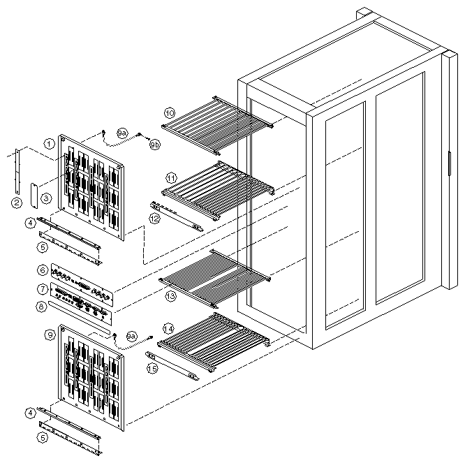
For a description of components seen in the rack chassis rear-left view, see Figure 1-5 and Table 1-8.
| Note: "CC2" means "Card Cage 2" [top rear of system]. "CC3" means "Card Cage 3" [bottom rear of system — optional]. |
Table 1-8. Components Shown in Rack Chassis Rear-Left View
ID | Description | SGI Part # | Chal | Onyx |
|---|---|---|---|---|
1 | CC2 REAR DOOR ASSY | X | X | |
2 | BLANK PANEL IO4 FILTER BD [1.125" x 7.875"] | X | X | |
3 | SPARE PLATE BLANK EVEREST [1.5" x 4.75"] | X | X | |
4 | HINGE | X | X | |
5 | EMI GASKET | X | X | |
6 | VIDEO I/O ASSY EVRY/TR PANEL I/O BLANK [not shown] | * X | X | |
7 | GENERAL I/O ASSY EVRY/TR | X | X | |
8 | VME™ CC3 SLOT LABEL GFX CC3 SLOT LABEL | X | * X | |
9
9a 9b | CC3 VME I/O DOOR PANEL CC3 GFX I/O DOOR PANEL CC3 BLANK DOOR ASSY CABLE RETAINING [Two cables included with item 9] SCREW 6-32X3/8 PNH PHH STL ZINC [2 per cable, 4 per system] | X * X X X | * X X X X | |
10 | CARD GUIDE TOP ASSY SVR CC2 -TOP CC2 TOP CARD GUIDE GFX | X | * X | |
11 | CARD GUIDE BOTTOM ASSY SVR CC2-BOT CC2 BOTTOM CARD GUIDE GFX | X | * X | |
12 | BOARD LOCK ASSY, TERM CC2,SERVER BOARD LOCK ASSY TERM CC2 GRAPHICS | X | * X | |
13 | CC3 TOP CARD GUIDE ASSY VME/GFX | X | X | |
14 | CC3 BOTTOM CARD GUIDE ASSY VME/GFX | X | X | |
15 | BOARD LOCK ASSY TERM CC3 | X | X |
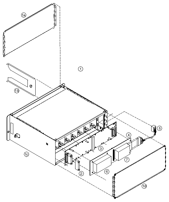
This section describes the rack SCSIBox2 assembly.
For a description of components in Figure 1-6, see Table 1-9.
Table 1-9. Components, SCSIBox2 Assembly
ID | Description | SGI Part # | Chal | Onyx |
|---|---|---|---|---|
| STUBBI SCSI BOX-RACK SYST [All in Figure 1-6] | X | X | |
| SCSI BOX ASSEMBLY TR [Items 1 through 5, below] | X | X | |
1 1a 1b 1c 1d | SCSI BOX ASSY SHEET METAL CHASSIS COVER ASSY FRONT SCSI BOX DRIVE SHELF ASSY SCSI BOX [8 used in each SCSIBox] CHASSIS ASSY SCSI BOX COVER ASSY REAR SCSI BOX | X X X X X | X X X X X | |
2 | TERMINATOR DIFF. PASSIVE, LOW PROFILE TERMINATOR SINGLE-ENDED ACTIVE, LOW PRO. | X X | X X | |
3 | PCA SCSI BACKPLANE | X | X | |
4 | PCA 512S POWER BD | X | X | |
5 | HARNESS ASSY SCSI CNT [512S to 48V source] | X | X | |
6 | DC-DC BRICK 5V@40A | X | X | |
7 | DC-DC BRICK 12V@17A | X | X |
| Note: This section describes the SCSIBox2 used in the main rack chassis. This SCSIBox2 is also known as "Stubbi SCSI." It should not be confused with the SCSIBox2 used in the CHALLENGEvault XL. That unit runs directly off of AC, whereas this unit uses 48VDC. The vault version is also significantly deeper, and does not fit into a CHALLENGE XL or Onyx XL chassis. |
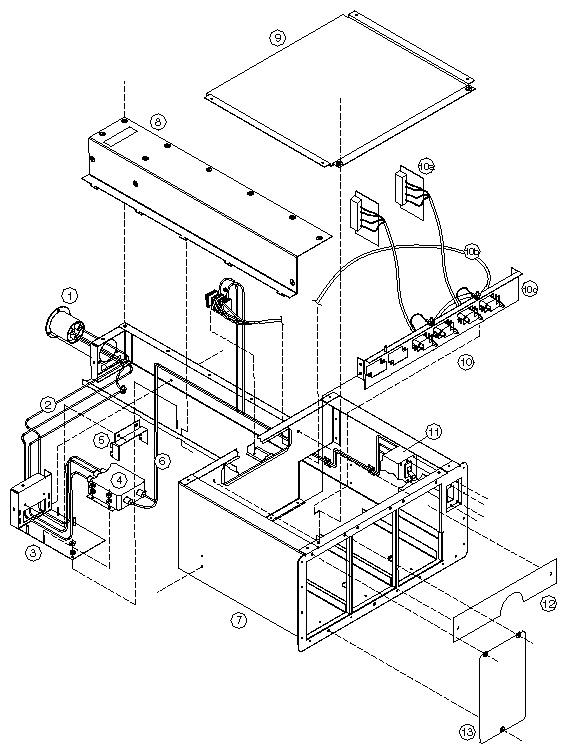
This section describes the rack power assemblies.
See Section 3.3, "OLS Assembly," for details on the off-line switcher (OLS) and Section 3.4.1, "Power Cables" for details of the power cables.
For a description of components in Figure 1-7, see Table 1-10.
Table 1-10. Components, Rack Power Tray Assembly (North American)
ID | Description | SGI Part # | Chal | Onyx |
|---|---|---|---|---|
| RACK POWER TRAY ASSEMBLY [North American] | X | X | |
1 | AC INPUT RECEPTACLE ASSY | X | X | |
2 | GND WIRE AC INPUT TO LINE FILTER | X | X | |
3 | BRACKET EMI FILTER OLS SHELF | X | X | |
4 | FILTER LINE SINGLE PHASE | X | X | |
5 | COVER EMI FILTER OLS 2 PHASE | X | X | |
6 | CABLE ASSY LINE FILTER TO CKT BREAKER TO PWR BLOCKS | X | X | |
7 | RIVETED ASSY OLS SHELF | X | X | |
8 | COVER TUNNEL OLS SHELF | X | X | |
9 | COVER TOP OLS SHELF | X | X | |
10 10a 10b 10c | AC/DC DISTRIBUTION BRACKET ASSY CABLE ASSY OLS TO CC3 POWER BD [2 used] CABLE ASSY AC/DC DIST. BRACKET TO PWR BLOCKS DISTRIBUTION BRACKET [metal bar only] | X X X X | X X X X | |
11 | CIRCUIT BREAKER 50/60HZ 40A | X | X | |
12 | OLS AIR COVER [Not included with power tray assembly.] | X | X | |
13 | OLS FRONT PLATE BLANK [In place of one OLS] | X | X |
See Section 3.3, "OLS Assembly," for details on the off-line switcher (OLS) and Section 3.4.1, "Power Cables" for details of the power cables.
For a description of components in Figure 1-8, see Table 1-11.
Table 1-11. Components, CC3 Rack Power Tray Assembly (208V North American)
ID | Description | SGI Part # | Chal | Onyx |
|---|---|---|---|---|
| RACK POWER TRAY ASSY 208V [N. Amer. w/ CC3] | X | X | |
1 | CABLE ASSY PWR 3PH DOM 30A 250V | X | X | |
2 | WIRE ASSY GROUND STRAP 3-PHASE [2 used] | X | X | |
3 | BRACKET 3 PH FILTER | X | X | |
4 | FILTER LINE 36A 440/250V AC 3 PHASE | X | X | |
5 | CABLE ASSY LINE FILTER TO CIRCUIT BREAKER TO PWR BLOCKS | X | X | |
6 | RIVETED ASSY OLS SHELF | X | X | |
7 | COVER TUNNEL OLS SHELF | X | X | |
8 | COVER TOP OLS SHELF | X | X | |
9 9a 9b 9c | AC/DC DIST ASSY 3 PHASE 220V CABLE ASSY OLS TO CC3 POWER BD [3 used] CABLE ASSY AC/DC DIST. BCKT TO PWR BLOCKS [220V 3ph] DISTRIBUTION BRACKET [metal bar only] | X X X X | X X X X | |
10 | CIRCUIT BREAKER 3PST 250/400VAC 30A | X | X | |
11 | OLS AIR COVER [Not included with power tray assembly.] | X | X |
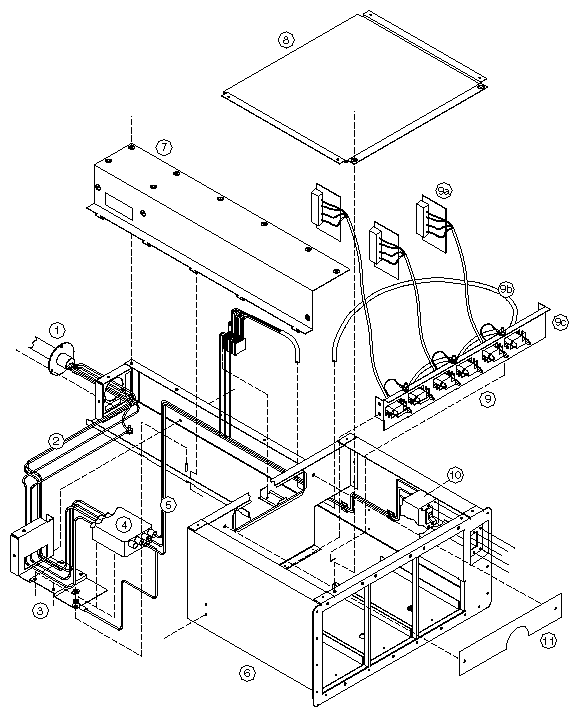
For a description of components in Figure 1-9, see Table 1-12.
See Section 3.3, "OLS Assembly," for details on the off-line switcher (OLS) and Section 3.4.1, "Power Cables" for details of the power cables.
Table 1-12. Components, CC3 Rack Power Tray Assembly (400V International)
ID | Description | SGI Part # | Chal | Onyx |
|---|---|---|---|---|
| RACK POWER TRAY ASSY 400V [Internat. w/ CC3] | X | X | |
1 | CABLE ASSY PWR 3PH INTL 32A 400V | X | X | |
2 | WIRE ASSY GROUND STRAP 3-PHASE [2 used] | X | X | |
3 | BRACKET 3 PH FILTER | X | X | |
4 | FILTER LINE 36A 440/250V AC 3 PHASE | X | X | |
5 | CABLE ASSY LINE FILTER TO CRCT BREAKER TO PWR BLOCKS | X | X | |
6 | RIVETED ASSY OLS SHELF | 013-0552-xxx | X | X |
7 | COVER TUNNEL OLS SHELF | X | X | |
8 | COVER TOP OLS SHELF | X | X | |
9 9a 9b 9c | AC/DC DIST ASSY 3 PHASE 400V CABLE ASSY OLS TO CC3 POWER BD [3 used] CABLE ASSY AC/DC DIST. BCKT TO PWR BLOCKS [400V 3ph] DISTRIBUTION BRACKET [metal bar only] | X X X X | X X X X | |
10 | CIRCUIT BREAKER 3PST 250/400VAC 30A | X | X | |
11 | OLS AIR COVER [Not included with power tray assembly.] | X | X |