This chapter illustrates the printed circuit assemblies for CHALLENGE and Onyx rack and deskside systems.
The chapter includes:
CPU board assemblies (Section 4.1)
Memory board assembly (Section 4.2)
Interface board assemblies (Section 4.3)
Power board assemblies (Section 4.4)
Midplane and backplane assemblies (Section 4.5)
Graphics board assemblies (Section 4.6)
Air deflector board assemblies (Section 4.7)
 | Note: This chapter shows SGI part numbers with a generic dash number (-xxx). Some system configurations require specific board revisions to work properly. Board revision details may be found in engineering change orders (ECOs) and field information bulletins (FIBs). Contact a support specialist to determine board revisions for a specific configuration. |
This section illustrates the SGI Everest CPU boards.
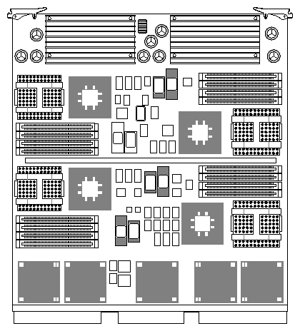
Table 4-1 identifies the configurations of the IP19 board.
Table 4-1. IP19 CPU Board Configurations
Description | SGI Part # |
|---|---|
PCA IP19 1-CPU 100MHZ 1MBSC PCA IP19 2-CPU 100MHZ 1MBSC PCA IP19 4-CPU 100MHZ 1MBSC | |
PCA IP19 1-CPU 150MHZ 1MBSC PCA IP19 2-CPU 150MHZ 1MBSC PCA IP19 4-CPU 150MHZ 1MBSC | |
PCA IP19 1-CPU 200MHZ 1MBSC PCA IP19 2-CPU 200MHZ 4MBSC PCA IP19 4-CPU 200MHZ 4MBSC |
![Figure 4-2 IP21 CPU Board [2-CPU version shown]](figures/030_0625.gif)
Table 4-2 identifies the configurations of the IP21 board.
Table 4-2. IP21 CPU Board Configurations
Description | SGI Part # |
|---|---|
PCA IP21 1-CPU 75MHZ 4MBSC PCA IP21 2-CPU 75MHZ 4MBSC |
030-0625-xxx |
PCA IP21 1-CPU 90MHZ 4MBSC PCA IP21 2-CPU 90MHZ 4MBSC [server] PCA IP21 2-CPU 90MHZ 4MBSC [graphics] |
030-0702-xxx 030-0858-xxx |
This section illustrates the SGI Everest memory board.
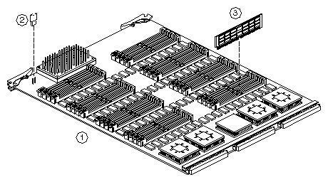
For a description of components in Figure 4-3, refer to Table 4-3.
Table 4-3. Components of MC3 Memory Board
ID | Description | SGI Part # |
|---|---|---|
1 | PCA MC3 PCA MC3 PCA MC3 PCA MC3 PCA MC3 | |
2 | JMPR 2P F BLK.1"LS 120K OHM RES [Reduces VCC from +5.0V to +4.9V, only used on some MC3 boards] | 9093305 |
3 | PCA SIMM 16MB 60NS PCA SIMM 64MB 60NS |
Table 4-4 lists the currently shipping MC3 board RAM configurations.
Since SIMMs are sometimes added by the customer, the shipped board configuration may be different from the current board configuration.
Table 4-4. Currently Shipping MC3 Board RAM Configuration
Assembly # | Shipped With | RAM Configuration |
|---|---|---|
030-0604-xxx | 64 MB | 4x16 MB |
030-0613-xxx | 256 MB | 4x64 MB |
030-0614-xxx | 0 MB | none |
This section illustrates the SGI Everest interface boards.
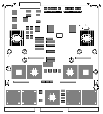
Table 4-5 identifies the three versions of the IO4 board.
For a description of components in Figure 4-5, refer to Table 4-6.
Table 4-6. Components of First IO4 Board With VCAM, SCSI Adapters
ID | Description | SGI Part # |
|---|---|---|
| BOARD ASSY FIRST IO4 [Includes one each of items 1, 2, 4a, 4b, 5, six of item 6, four of item 7, and labels] | |
1 | PCA IO4 or PCA IO4B | See Table 4-5 |
2 | PCA VCAM | |
3 | FUSE 2A 125V SUBMIN PLUG-IN .1LS [Used in 3 places on 030-0240-xxx & 030-0377-xxx. Replaced with self-resetting polyswitch on 030-0646-xxx.] | |
4
| PCA SCSI ADAPTER MODULE SE (green) PCA SCSI ADAPTER MODULE DF (red) | |
5 | PCA IO4 ADAPTER | |
6 | SCREW 4-40X3/16" PNH PH STL/ZNC PL [6 used] | |
7 | SCREW 6X1/4 TRUSS HD PHILLIP STL/ZN [4 used] |
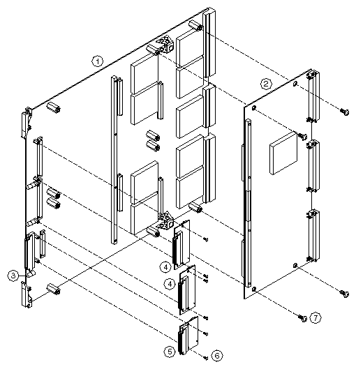
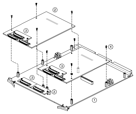
For a description of components in Figure 4-6, refer to Table 4-7.
Table 4-7. Components of IO4 Board With Mezzanine Boards
ID | Description | SGI Part # |
|---|---|---|
1 | PCA IO4 | See Table 4-5 |
2 | PCA MEZZ S1 | |
| PCA MEZZ F SHORT [not shown] PCA MEZZ F LONG [not shown] PCA MEZ_SCIP [not shown] PCA GCAM [not shown] | |
3 | PCA SCSI ADAPTER MODULE SE [green] PCA SCSI ADAPTER MODULE DF [red] | |
4 | SCREW 4-40X3/16" PNH PH STL/ZNC PL [4 or 6 used with each Mezz card.] |
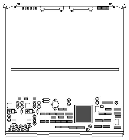
For a description of the board in Figure 4-7, refer to Table 4-8.
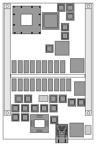
For a description of the board in Figure 4-8, refer to Table 4-9.
This section illustrates the SGI power boards.
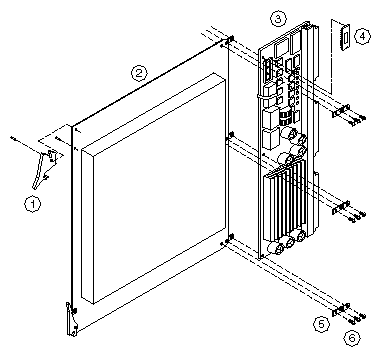
For a description of components in Figure 4-9, see Table 4-10
Table 4-10. Components of System Controller Power Board Assembly
ID | Description | SGI Part # |
|---|---|---|
| SYSTEM CONTROLLER POWER BD ASSY | |
1 | CIRCUIT BOARD EXTRACTOR [2 used] | |
2 | EXTENDER POWER BOARD -TR | |
3 | PCA EBUS PCA EBUS POWER BD | |
4 | EPROM ASSY 27C010 32DIP CKSM EPROM version 2.02 EPROM version 2.03 EPROM version 3.10 EPROM version 3.20 |
070-1117-007 |
5 | TAB EXTENDER POWER BOARD [3 used] | |
6 | SCREW 4-40X1/4 PNH PHH STL ZINC [9 used] |
For a description of components in Figure 4-10, refer to Table 4-11
Table 4-11. Components of 512 Power Board Assembly
ID | Description | SGI Part # |
|---|---|---|
| 512 POWER BOARD ASSEMBLY | |
1 | CIRCUIT BOARD EXTRACTOR | |
2 | EXTENDER POWER BOARD -TR | |
3 | PCA 512 POWER BOARD | |
4 | TAB EXTENDER POWER BOARD [3 used] | |
5 | SCREW 4-40X1/4 PNH PHH STL ZINC [9 used] |
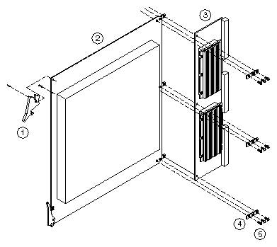
For a description of components in Figure 4-11, refer to Table 4-12.
Table 4-12. Components of 505 Power Board Assembly
ID | Description | SGI Part # |
|---|---|---|
| POWER BOARD EXTENDER ASSY 505 | |
1 | CIRCUIT BOARD EXTRACTOR | |
2 | EXTENDER POWER BOARD -TR | |
3 | PCA POWER BD 505 | |
4 | TAB EXTENDER POWER BOARD [3 used] | |
5 | SCREW 4-40X1/4 PNH PHH STL ZINC [9 used] |
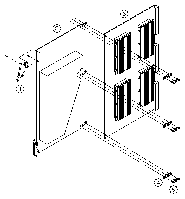
For a description of components in Figure 4-12, refer to Table 4-13.
Table 4-13. Components of 505X2 Power Board Assembly
ID | Description | SGI Part # |
|---|---|---|
| 505X2 POWER BOARD ASSEMBLY | |
1 | CIRCUIT BOARD EXTRACTOR | |
2 | EXTENDER BOARD FOR 505X2 | |
3 | PCA 505X2 POWER BOARD | |
4 | TAB EXTENDER POWER BOARD [3 used] | |
5 | SCREW 4-40X1/4 PNH PHH STL ZINC [9 used] |
This section illustrates midplane and backplane assemblies.
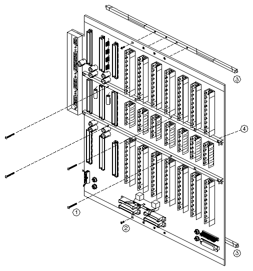
For a description of components in Figure 4-13, refer to Table 4-14.
Table 4-14. Components of Server Midplane Assembly
ID | Description | SGI Part # |
|---|---|---|
| PCA TERM SERVER BP TESTED | |
1 | SCR 4-40X0.88"L PNH PHH STEEL ZINC [12 used] | |
2 | SCREW 2-56X.25 FH PH STL W/ZINC [8 used per board] | |
3 | RETAINER MIDPLANE/BACKPLANE 16"L ["Wedgelock," 2 used per board] | |
4 | STIFFENER MID-PLANE [4 used] |
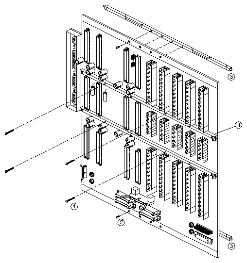
For a description of components in Figure 4-14, refer to Table 4-15.
Table 4-15. Components of Graphics Midplane Assembly
ID | Description | SGI Part # |
|---|---|---|
| PCA MIDPLANE GRAPHICS | |
| PCA TERM GFX 3.3/5V BP [Kona-ready, not shown] | |
1 | SCR 4-40X0.88"L PNH PHH STEEL ZINC [12 used] | |
2 | SCREW 2-56X.25 FH PH STL W/ZINC [8 used per board] | |
3 | RETAINER MIDPLANE/BACKPLANE 16"L ["Wedgelock," 2 used per board] | |
4 | STIFFENER MID-PLANE [4 used] |
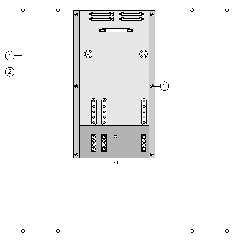
For a description of components in Figure 4-15, refer to Table 4-16.
Table 4-16. Components of CC3 Power Jumper Board Assembly
ID | Description | SGI Part # |
|---|---|---|
| CC3 POWER BOARD ASSY | |
1 | ADAPTER CC POWER JUMPER [metal frame] | |
2 | PCA CC3 PWR JUMPER [circuit board only] | |
3 | SCREW 6-32X1/4LG T-TITE PNH PHH ZN [6 used] |
| Note: The CC3 power jumper board contains the inlet temperature sensor for the rack system. The temperature sensor, however, is not a separately replaceable item. |
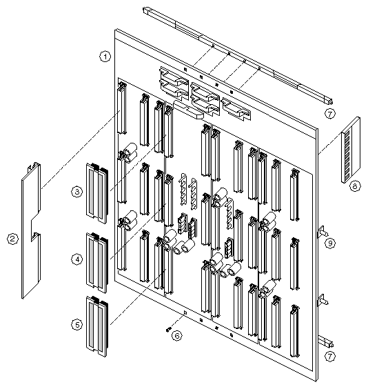
For a description of components in Figure 4-16, refer to Table 4-17.
Table 4-17. Components of CC3 VME Backplane Assembly
ID | Description | SGI Part # |
|---|---|---|
1 | CC3 VME BACKPLANE | |
2 | CC3 BACKPLANE VME TERMINATOR [1, 2 or 3 per system, depend. on config.] | |
3 | J1 JUMPER BOARD FOR VME BACKPLANE CC3 | |
4 | J2 JUMPER BOARD FOR VME BACKPLANE CC3 | |
5 | J3 JUMPER BOARD FOR VME BACKPLANE CC3 | |
6 | SCREW 2-56X.25 FH PH STL W/ZINC [8 used per board] | 7270173 |
7 | RETAINER MIDPLANE/BACKPLANE 16"L ["Wedgelock," 2 used per board] | |
8 | CC3 INTERRUPT BOARD | |
9 | STIFFENER CC3 BACKPLANE [2 used per board] | |
| SCREW 4-40X.625LG UNC PNH PHH [6 used per stiffener, not shown] | 7270158 |
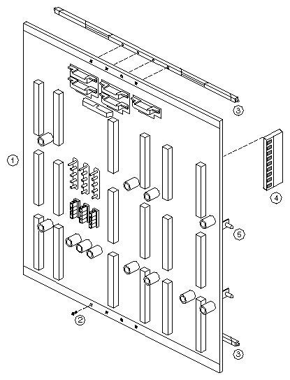
For a description of components in Figure 4-17, refer to Table 4-18.
Table 4-18. Components of CC3 GFX Backplane Assembly
ID | Description | SGI Part # |
|---|---|---|
1 | CC3 GFX BACKPLANE | |
2 | SCREW 2-56X.25 FH PH STL W/ZINC [8 used per board] | 7270173 |
3 | RETAINER MIDPLANE/BACKPLANE 16"L ["Wedgelock," 2 used per board] | |
4 | CC3 INTERRUPT BOARD | |
5 | STIFFENER CC3 BACKPLANE [2 used per board] | |
| SCREW 4-40X.625LG UNC PNH PHH [6 used per stiffener, not shown] | 7270158 |
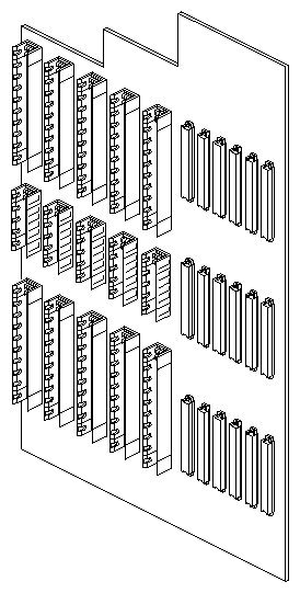
For a description of the assembly in Figure 4-18, refer to Table 4-19.
Table 4-19. Components of Deskside Server Backplane Assembly
Description | SGI Part # |
|---|---|
PCA BACKPLANE SERVER | |
BACKPLANE ASSY SERVER CHAL DM [simply an 030-0314-xxx backplane with the hardware below, not shown] | |
WASHER FL.173 IDX.625 ODX.03THK ST [For CHALLENGE DM, not shown] | |
SCREW 8-32X3/8L TAMPER PROOF [For CHALLENGE DM, not shown] | |
COLLAR STEEL (TAMPER PROOF SCREW) [For CHALLENGE DM, not shown] |
| Note: 48 volt power-cable connections are: RE92 connects to E1, RE91 connects to E2, RE85 connects to E3, and RE86 connects to E4. |
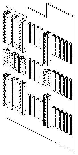
For a description of the assembly in Figure 4-19, refer to Table 4-20.
Table 4-20. Components of Deskside Graphics Backplane Assembly
Description | SGI Part # |
|---|---|
PCA BACKPLANE GFX | |
PCA BACKPLANE 3.3/5V KONA GFX DESKS [Not shown] | |
WASHER NYL.032THK X.149ID X.312OD [Not shown, for use with 030-0555-001] |
| Note: 48 volt power-cable connections are: RE92 connects to E1, RE91 connects to E2, RE85 connects to E3, and RE86 connects to E4. |
| Note: The two left-hand mounting holes on the earliest revision of the Kona-ready backplane (030-0555-001) require insulating washers, such as 7280082 listed above. |
This section illustrates the SGI graphics board assemblies.
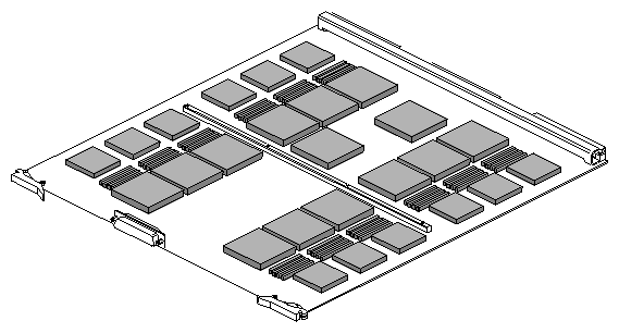
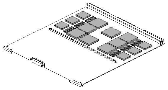
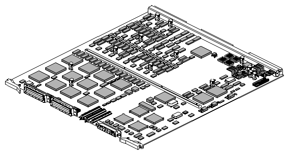
Table 4-21 identifies two configurations of the DG2 board.
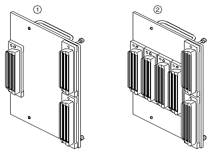
For a description of the boards in Figure 4-23, refer to Table 4-22.
Table 4-22. DI1 and DI4 Boards
ID | Description | SGI Part # |
|---|---|---|
1 | PCA DI4 [used in VTX systems] | |
2 | PCA DI1 [used in RealityEngine systems] |
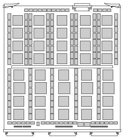
Table 4-23 identifies two configurations of the RM4 board.
Table 4-23. RM4 Memory Board Configurations
Description | SGI Part # |
|---|---|
PCA RM4 | |
PCA RM4T [can substitute for an RM4 by removing the SIP terminators parallel to and next to the backplane connectors] | |
TERM 10-PIN RC 68 OHM/56PF SIP [Not shown] |
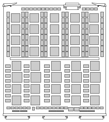
Table 4-24 identifies two configurations of the RM5 board.
Table 4-24. RM5 Memory Board Configurations
Description | SGI Part # |
|---|---|
PCA RM5 | |
RM5T [can substitute for an RM4 by removing the SIP terminators parallel to and next to the backplane connectors] | |
TERM 10-PIN RC 68 OHM/56PF SIP [Not shown] |
This section illustrates the SGI air deflector board assemblies.
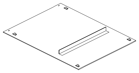
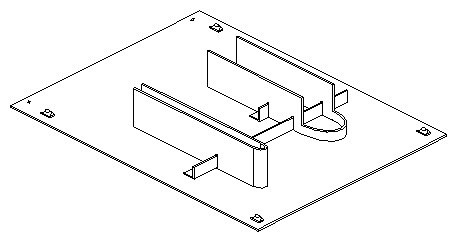
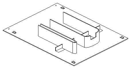
![Figure 4-29 9U Baffle Board Assembly (013-0689-xxx) [sheet-metal and foam]](figures/013_0689.gif)
![Figure 4-30 9U Baffle Board Assembly (013-0948-xxx) [molded plastic]](figures/013_0948.gif)