This chapter explains
isolating a node (preparing to swap an IO4 board)
replacing a log disk
exchanging Challenge RAID disk modules
restoring LUN ownership on a RAID system
This section explains how to isolate a node (for example, 1) with a failed component from the other node (in this case, 2), which is still running OPS. This technique allows several maintenance procedures to be applied. For example, you can replace the IO4 or the SCIP mez card that affects the SCSI chains joining the two nodes.
The procedures are
breaking the SCSI chain with the shared RAID
breaking the SCSI chain with the log disks
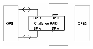
Figure 4-1 shows that data between the two OPS Challenge systems (OPS1 and OPS2) flows to and from the shared Challenge RAID.
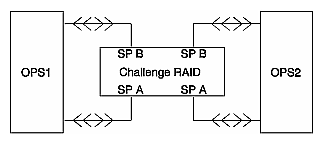
To break the SCSI chain with the shared Challenge RAID, follow these steps:
Power off the host (node) whose IO4 board you want to replace. In this example, it is node 2 (OPS2).
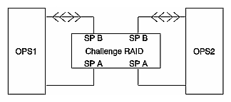
Turn off SP A, as diagrammed in Figure 4-2.
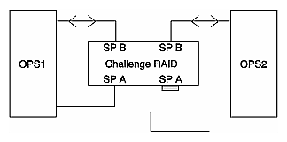
Remove the cable connecting SP A to the host (node) whose IO4 board you want to replace (in this example, OPS2). Place a differential terminator on A1, as diagrammed in Figure 4-3.
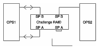
Turn on SP A. Data flow changes, as diagrammed in Figure 4-4.
Wait five minutes for SP A to come online.
After five minutes have passed, verify that SP A is online by issuing this raidcli command:
/usr/raid5/raidcli getcrus
The output should contain the line
SPA State: Present
Power off SP B. Remove the cable connecting SP B to node 1; place a differential terminator on B1, as diagrammed in Figure 4-5.
Turn on SP B.
Follow instructions for replacing the IO4 board in the CHALLENGE/Onyx XL Rackmount Installation Instructions or CHALLENGE/Onyx L Deskside Installation Instructions.
In this section, terms are used as follows:
log disks: 1X 1Y 1Z are the log disks primarily written by node 1 and mirrored on 1x 1y 1z. Similarly, 2X 2Y 2Z are the log disks primarily written by node 2 and mirrored on 2x 2y 2z.
vaults: V and v, containing 1X 1Y 1Z 2X 2Y 2Z, and 1x 1y 1z 2x 2y 2z, respectively. 1X 1Y 1Z should be on one SCSI bus within V; 2X 2Y 2Z should be on the other SCSI bus of V. Similarly for the mirror disks.
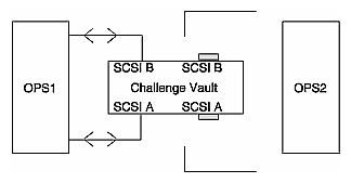
To break the SCSI chain with the log disks on a vault V, follow these steps:
Verify that you can see all the log files by issuing the following SQLDBA command from an instance:
connect internal
select * from v$logfile
Make all disks within vault V inactive by issuing the following SQLDBA commands from any instance:
ALTER DATABASE DROP LOGFILE MEMBER '/dev/rdsk/1X';
ALTER DATABASE DROP LOGFILE MEMBER '/dev/rdsk/1Y';
ALTER DATABASE DROP LOGFILE MEMBER '/dev/rdsk/1Z';
ALTER DATABASE DROP LOGFILE MEMBER '/dev/rdsk/2X';
ALTER DATABASE DROP LOGFILE MEMBER '/dev/rdsk/2Y';
ALTER DATABASE DROP LOGFILE MEMBER '/dev/rdsk/2Z';

Note: A log file will not be dropped if it is part of the currently active log group or if it is part of the log group that is currently being archived. For the log group that is currently being archived, wait for archiver to finish archiving it and reexecute the DROP command for the file.
For the log group that is the current group, switch to the next group and then reexecute the DROP command for the file.
To switch a log group for an instance, the following command must be executed from that instance:
ALTER SYSTEM SWITCH LOGFILE;
Verify that the log file members have actually been dropped by issuing the following SQLDBA command from any instance:
connect internal
select * from v$logfile
Power off vault V.
Disconnect the cables connecting V to OPS2; place differential terminators on V where the cables were.
Disconnect FDDI cables and lines, and other network or communication links.
OPS2 is now isolated.
Add the LOG files back to Oracle by executing the following SQLDBA commands from any instance:
ALTER DATABASE ADD LOGFILE MEMBER '/dev/rdsk/1X' REUSE TO GROUP 1;
ALTER DATABASE ADD LOGFILE MEMBER '/dev/rdsk/1Y' REUSE TO GROUP 2;
ALTER DATABASE ADD LOGFILE MEMBER '/dev/rdsk/1Z' REUSE TO GROUP 3;
ALTER DATABASE ADD LOGFILE MEMBER '/dev/rdsk/2X' REUSE TO GROUP 4;
ALTER DATABASE ADD LOGFILE MEMBER '/dev/rdsk/2Y' REUSE TO GROUP 5;
ALTER DATABASE ADD LOGFILE MEMBER '/dev/rdsk/2Z' REUSE TO GROUP 6;
Verify that the log files actually got added by executing the following SQLDBA commands from any instance:
connect internal
select * from v$logfile
The newly added log files might show a status of INVALID.
Cycle through all the log groups by executing the following from each instance:
ALTER SYSTEM SWITCH LOGFILE;
ALTER SYSTEM SWITCH LOGFILE;
ALTER SYSTEM SWITCH LOGFILE;
This section contains procedures on replacing cables:
replacing a cable on the SCSI chain with the RAID
replacing FDDI cables or serial lines
replacing a cable on the SCSI chain with the log disks
To replace a nonfunctional cable connecting the IO4 board in OPS1 (I1) to SP A, follow these steps:
Power down node 1.
Turn off SP A.
Replace the cable from A1 to I1 (host 1).
Turn on SP A.
Follow these steps:
Back up and shut down Oracle.
Stop the CM:
killall -TERM opscm
Replace the defective cable.
Bring up the CM and Oracle.
In this section, terms are used as follows:
log disks: 1X 1Y 1Z are the log disks primarily written by node 1 and mirrored on 1x 1y 1z. Similarly, 2X 2Y 2Z are the log disks primarily written by node 2 and mirrored on 2x 2y 2z.
vaults: V and v, containing 1X 1Y 1Z 2X 2Y 2Z and 1x 1y 1z 2x 2y 2z, respectively. 1X 1Y 1Z should be on one SCSI bus within V; 2X 2Y 2Z should be on the other SCSI bus of V. Similarly for the mirror disks.
To replace a nonfunctional cable from the IO4 board in OPS2 (I2) to vault 1 (V), follow these steps:
Follow steps 1 through 7 in Section 4.1.2, "Breaking the SCSI Chain With the Log Disks," earlier in this chapter.
Replace the cable between OPS2 and vault V.
Power on vault V.
Do a dummy I/O on all the disks in the vault from both nodes.
dd if=/dev/rdsk/1X of=/dev/null count=1
dd if=/dev/rdsk/1Y of=/dev/null count=1
dd if=/dev/rdsk/1Z of=/dev/null count=1
dd if=/dev/rdsk/2X of=/dev/null count=1
dd if=/dev/rdsk/2Y of=/dev/null count=1
dd if=/dev/rdsk/2Z of=/dev/null count=1
It is OK if some of the dd's return an error.
Repeat the dd's from both nodes.
dd if=/dev/rdsk/1X of=/dev/null count=1
dd if=/dev/rdsk/1Y of=/dev/null count=1
dd if=/dev/rdsk/1Z of=/dev/null count=1
dd if=/dev/rdsk/2X of=/dev/null count=1
dd if=/dev/rdsk/2Y of=/dev/null count=1
dd if=/dev/rdsk/2Z of=/dev/null count=1
This time all the dd's should succeed.
Verify the current log files by executing the following SQLDBA statement from any node.
connect internal
select * from v$logfile
Add the log files back to Oracle by executing the following SQLDBA commands from any node:
ALTER DATABASE ADD LOGFILE MEMBER '/dev/rdsk/1X' REUSE TO GROUP 1;
ALTER DATABASE ADD LOGFILE MEMBER '/dev/rdsk/1Y' REUSE TO GROUP 2;
ALTER DATABASE ADD LOGFILE MEMBER '/dev/rdsk/1Z' REUSE TO GROUP 3;
ALTER DATABASE ADD LOGFILE MEMBER '/dev/rdsk/2X' REUSE TO GROUP 4;
ALTER DATABASE ADD LOGFILE MEMBER '/dev/rdsk/2Y' REUSE TO GROUP 5;
ALTER DATABASE ADD LOGFILE MEMBER '/dev/rdsk/2Z' REUSE TO GROUP 6;
Verify that the log files actually got added by executing the following SQLDBA commands from any node:
connect internal
select * from v$logfile
The newly added log files may show a status of INVALID.
Cycle through all the log groups by executing the following from each instance:
ALTER SYSTEM SWITCH LOGFILE;
ALTER SYSTEM SWITCH LOGFILE;
ALTER SYSTEM SWITCH LOGFILE;
To replace a nonfunctional log disk (1X), follow these steps:
Follow steps 1 through 6 in Section 4.1.2, "Breaking the SCSI Chain With the Log Disks," earlier in this chapter.
Replace the nonfunctional disk in vault V.
Power on vault V.
Do a dummy I/O on all the disks in the vault from both nodes.
dd if=/dev/rdsk/1X of=/dev/null count=1
dd if=/dev/rdsk/1Y of=/dev/null count=1
dd if=/dev/rdsk/1Z of=/dev/null count=1
dd if=/dev/rdsk/2X of=/dev/null count=1
dd if=/dev/rdsk/2Y of=/dev/null count=1
dd if=/dev/rdsk/2Z of=/dev/null count=1
It is OK if some of the dd's return an error.
Repeat the dd's from both nodes.
dd if=/dev/rdsk/1X of=/dev/null count=1
dd if=/dev/rdsk/1Y of=/dev/null count=1
dd if=/dev/rdsk/1Z of=/dev/null count=1
dd if=/dev/rdsk/2X of=/dev/null count=1
dd if=/dev/rdsk/2Y of=/dev/null count=1
dd if=/dev/rdsk/2Z of=/dev/null count=1
This time all the dd's should succeed.
Verify the current log files by executing the following SQLDBA statement from any instance:
connect internal
select * from v$logfile
Add the LOG files back to Oracle by executing the following SQLDBA commands from any instance:
ALTER DATABASE ADD LOGFILE MEMBER '/dev/rdsk/1X' REUSE TO GROUP 1;
ALTER DATABASE ADD LOGFILE MEMBER '/dev/rdsk/1Y' REUSE TO GROUP 2;
ALTER DATABASE ADD LOGFILE MEMBER '/dev/rdsk/1Z' REUSE TO GROUP 3;
ALTER DATABASE ADD LOGFILE MEMBER '/dev/rdsk/2X' REUSE TO GROUP 4;
ALTER DATABASE ADD LOGFILE MEMBER '/dev/rdsk/2Y' REUSE TO GROUP 5;
ALTER DATABASE ADD LOGFILE MEMBER '/dev/rdsk/2Z' REUSE TO GROUP 6;
Verify that the log files actually got added by executing the following SQLDBA commands from any instance:
connect internal
select * from v$logfile
The newly added log files might show a status of INVALID.
Cycle through all the log groups by executing the following from each instance:
ALTER SYSTEM SWITCH LOGFILE;
ALTER SYSTEM SWITCH LOGFILE;
ALTER SYSTEM SWITCH LOGFILE;
For convenience, this section reproduces information from the CHALLENGE RAID Installation and Maintenance Instructions. For complete instructions on replacing field-replaceable units, see that manual.
 | Caution: Before you follow the procedures explained in this chapter, note the following: |
To prevent thermal shutdown of the storage system, never operate it for more than two minutes with the fan module open.
Never remove more than one disk module or disk filler module at a time.
Disk modules A0, B0, C0, D0, and E0 contain special system firmware for Challenge RAID storage systems. Do not remove disk modules from bus 0 (the top five modules on the right) for use in other disk module positions.
Although you can remove a disk module (other than those in bus 0) without damaging the disk data, do this only when the disk module has actually failed. Never remove a disk module unless you are installing its replacement.
Removing the wrong drive module can introduce an additional fault that shuts down the physical disk containing the failed module. Before removing a disk module, verify that the suspected module has actually failed.
Use only Challenge RAID disk modules as replacements; only they contain the correct device firmware. The replacement 2 GB drive part number is 9410113; the replacement 4.3 GB drive part number is 9410114. Other disk modules, even those from other Silicon Graphics equipment, will not work. Do not mix disk modules of different capacities within one array.
When removed from the chassis, the disk modules are extremely sensitive to shock and vibration. Even a slight jar can severely damage them.
Do not operate the system with an open storage-control processor slot.
SCSI terminators must be in place at all times during operation. Removing them causes the storage system to crash.
If you replace a disk module, you must update the firmware as explained in Section 4.4.2.4, "Updating the Disk Module Firmware."
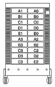
Figure 4-7 diagrams the location of disks, which can be replaced by owners or SSEs.
| Note: For information on replacing other field-replaceable units (FRUs) in the Challenge RAID, see the CHALLENGE RAID Installation and Maintenance Guide. For information on replacing SCSI-2 adapters in the Challenge server, see the Challenge server documentation. |
This section explains
opening and closing the fan module
replacing or adding a disk module
installing an add-on disk module array
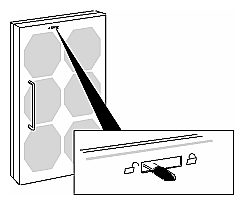
To remove or install an SP, power supply, or battery backup unit, you must unlock and swing open the fan module:
On the back of the storage system, move the fan module's latch to the UNLOCK position, as shown in Figure 4-8.
Swing open the fan module, as shown in Figure 4-9.
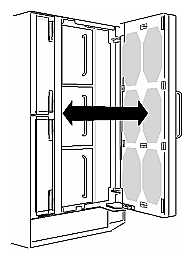
Close the fan module by reversing these steps.
| Caution: To prevent thermal shutdown of the storage system, never operate the storage system for more than two minutes with the fan module in the open position. |
This section explains
identifying a failed disk module
removing the failed disk module
installing the replacement disk module
updating the disk module firmware
If you have determined that a module has failed by examining the cabinet fault light or by using the raidcli getdisk or raidcli getcrus command, as explained in Chapter 3 in this guide, you can replace the defective module and rebuild your data without powering off the Challenge RAID storage system or interrupting user applications.
| Caution: Removing the wrong drive module can introduce an additional fault that shuts down the physical disk containing the failed module. Before removing a disk module, verify that the suspected module has actually failed. |
The fault indicator on a disk module does not necessarily mean that the drive itself has failed. Failure of a SCSI bus, for example, lights the fault indicator on each disk module on that bus.
To verify a suspected disk module failure, follow these steps:
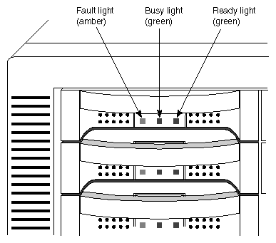
Look for the module with its amber fault light on. Figure 4-10 shows the fault indicator light and other lights on a disk module.
Determine the failed module's ID; see Figure 4-7.
Caution: Use only Challenge RAID disk modules to replace failed disk modules. Order them from the Silicon Graphics hotline. Challenge RAID disk modules contain proprietary firmware that the storage system requires for correct functioning. Using any other disks, including those from other Silicon Graphics systems, can cause failure of the storage system. If you have not already checked the module status with raidcli getdisk, do so now. See Appendix B of the CHALLENGE RAID Installation and Maintenance Instructions (007-0128-006) for complete information on raidcli parameters.
If you have not already checked the unsolicited error log with raidcli getlog for a message about the disk module, as explained in Appendix B of the CHALLENGE RAID Installation and Maintenance Instructions (007-0128-006), do so now.
A message about the disk module contains its module ID (such as A0 or B3). Check for any other messages that indicate a related failure, such as failure of a SCSI bus or a general shutdown of a chassis, that might mean the disk module itself has not failed.
| Caution: Although you can remove a disk module without damaging the disk data, do this only when the disk module has actually failed. Never remove a disk module unless absolutely necessary, and only when you have its replacement available. Never replace more than one disk module at a time; use only the correct disk modules available from Silicon Graphics. |
You can replace a failed disk module while the storage system is powered on. If necessary, you can also replace a disk module that has not failed, such as a module that has reported many "soft" errors. When replacing a module that has not failed, you must do so while the storage system is powered on so that the storage-control processor knows that the module is being replaced.
| Caution: To maintain proper cooling in the storage system, never remove a disk module until you are ready to install a replacement. Never remove more than one disk module at a time. |
To remove a disk module, follow these steps:
Verify that the suspected module has actually failed.
Caution: If you remove the wrong disk module, you introduce an additional fault that shuts down the physical disk containing the failed module. In this situation, the operating system software cannot access the physical disk until you initialize it again. When a disk fails, the storage-control processor automatically unbinds it. To check that the disk has been unbound, use the following raidcli command for the disk module position in question:
raidcli -d device getdisk [diskposition]
If necessary, get the device name first with raidcli getagent. See Appendix B for information on these parameters.
Locate the disk module that you want to remove; see Figure 4-7 if necessary.
Position the new disk module in its antistatic packaging within reach of the storage system.
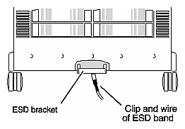
If you are using an ESD wrist strap, attach its clip to the ESD bracket at the bottom of the storage system, as shown in Figure 4-11. Put the wrist band around your wrist with the metal button against your skin.
Make sure that the disk has stopped spinning and that the heads have unloaded.
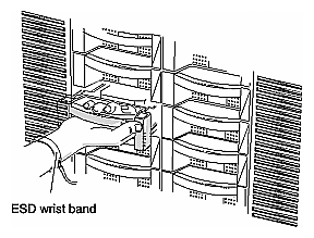
Grasp the disk module by its handle and pull it partway out of the cabinet, as shown in Figure 4-12.
Caution: Never remove more than one disk module at a time. Supporting the disk module with your free hand, pull it all the way out of the cabinet, as shown in Figure 4-13.
Caution: When removed from the chassis, the disk modules are extremely sensitive to shock and vibration. Even a slight jar can severely damage them. If necessary, on the label on the side of the disk module, write the ID number for the compartment from which you removed the drive; for example, A3.
For the compartment ID numbers, refer to Figure 4-7.
Put the failed disk module in an antistatic bag and store it in a place where it will not be damaged.
Caution: Before installing a replacement module, wait at least 15 seconds after removing the failed module to allow the storage-control processor time to recognize that the module has been removed. If you insert the replacement module too soon, the processor may report the replacement module as defective.
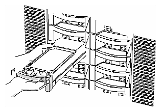
To install the replacement disk module, follow these steps:
Touch the new disk module's antistatic packaging to discharge it and the drive module. Remove the new disk module from its packaging.
Caution: The disk module is extremely sensitive to shock and vibration. Even a slight jar can severely damage it. Before installing a replacement module, wait at least 15 seconds after removing the failed module to allow the processor time to recognize that the module has been removed. If you insert the replacement module too soon, the processor may report the replacement module as defective.
Position the disk module in its antistatic packaging within reach of the storage system.
Locate the slot where you will install the disk module; see Figure 4-7.
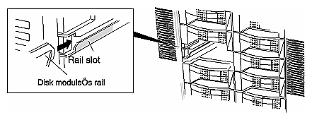
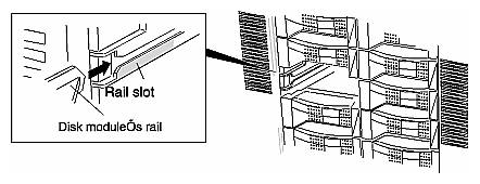
Engage the disk module's rail in the chassis rail slot, as shown in Figure 4-14.
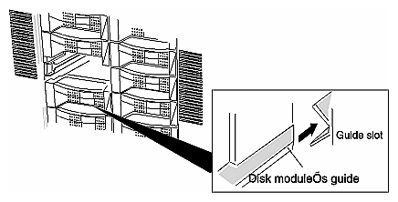
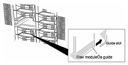
Engage the disk module's guide in the chassis guide slot, as shown in Figure 4-15.
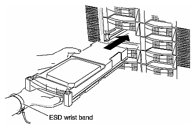
Insert the disk module, as shown in Figure 4-16. Make sure it is completely seated in the slot.
Remove and store the ESD wrist band, if you are using one.
The storage-control processor formats and checks the new module and then begins to reconstruct the data. While rebuilding occurs, you have uninterrupted access to information on the physical disk unit.
The default rebuild period is four hours.
| Note: During the rebuild period, performance might degrade slightly, depending on the rebuild time specified and on I/O bus activity. |
For more information on changing the default rebuild period, use raidcli bind, as explained in Appendix B of the CHALLENGE RAID Installation and Maintenance Instructions (007-0128-006).
If you have replaced a failed unbound disk module (A0, B0, C0, or A3), update the firmware on the Challenge RAID SP. The firmware (FLARE code) is stored in separate directories in /usr/raid5/flare:
/usr/raid5/flare/sauna7/flarecode.bin: use this for AMD-based SPs with FLARE code rev. level 7.xx
/usr/raid5/flare/sauna8/flarecode.bin: use this for AMD-based SPs with FLARE code rev. level 8.00 through 8.49
/usr/raid5/flare/phoenix8/flarecode.bin: use this for PowerPC-based SPs with FLARE code rev. level 8.50 through 8.99
/usr/raid5/flare/phoenix9/flarecode.bin: use this for PowerPC-based SPs with FLARE code rev. level 9.00 through 9.99
Follow these steps:
Quiesce the bus, disabling all applications. Make sure that only the RAID agent is running.
Enter as root
raidcli -d device firmware /usr/raid5/flare/directory/flarecode.bin
In this string, the new firmware image /usr/raid5/flare/<directory>/flarecode.bin contains microcode that runs on the SP and also a microcode image destined for the SP PROM, which runs the power-on diagnostics.
You must use this command every time you replace a failed unbound disk module (A0, B0, C0, or A3).
The image in the file given in the command contains microcode that runs on the storage-control processor and possibly also a microcode image destined for the storage-control processor PROM, which runs the power-on diagnostics.
This command has no output.
Use only Challenge RAID disk modules; only they contain the correct device firmware. Other disk modules, even those from other Silicon Graphics equipment, will not work. Do not mix disk modules of different capacities within one array. Do not remove disk modules from bus 0 (slots A0, B0, C0, D0, and E0) for use in other disk module positions.
Table 4-1 gives marketing codes for add-on disk module arrays. Add-on disk modules are available only in arrays of five.
Table 4-1. Ordering Add-On Disk Module Sets
Unit | Marketing Code |
|---|---|
Add-on five 2 GB drives | P-S-RAID-5X2 |
Add-on five 4.3 GB drives | P-S-RAID-5X4 |
Base array with five 2 GB drives | P-S-RAID-B5X2 |
Base array with five 4 GB drives | P-S-RAID-B5X4 |
Fill the slots in this order (consult Figure 4-7 if necessary):
| Caution: Never remove more than one disk module or disk filler module at a time. |
Position the new disk modules in their antistatic packaging within reach of the storage system.
If you are using a wrist band, attach its clip to the ESD bracket on the bottom of the storage system, as shown in Figure 4-11. Put the wrist band around your wrist with the metal button against your skin.
Locate the slots where you will install the add-on disk modules; see Figure 4-7.
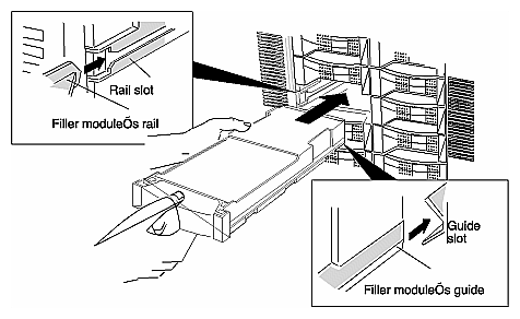
Grasp the filler module for the first slot and pull it out of the cabinet; set it aside. If you cannot grasp the module, use a medium-size flat-blade screwdriver to pry it out gently. See Figure 4-17.
Touch the new disk module's antistatic packaging to discharge it and the drive module. Remove the new disk module from its packaging.
Engage the disk module's rail in the chassis rail slot, as shown in Figure 4-18.
Caution: Disk modules are extremely sensitive to shock and vibration. Even a slight jar can severely damage them.
Engage the disk module's guide in the chassis guide slot, as shown in Figure 4-19.
Insert the disk module, as shown in Figure 4-19. Make sure it is completely seated in the slot.
As part of a SCSI component (SPs, cables, SCIP mez cards, IO4 boards) replacement procedure, the pertinent SP(s) must be powered down. At this time, accesses to the LUNs currently owned by a disabled SP are normally no longer possible.
When the SPs are turned back on (at the end of the replacement procedure), all LUNs continue to be owned by the other SP. This section explains how to restore the original status.
Patches shipped with OPS upgrade IRIX so that it contains a failover feature:
IRIX 6.2: patch 1228
IRIX 5.3 with XFS: patch 1314
If accesses to the LUNs on the RAID system are made through XLV volumes, and an SP fails (or is turned off), XLV code forces the remaining SP to take over ownership of all LUNs and redirects the accesses to the remaining SP.
This failover is transparent to the user (such as Oracle RDBMS) making the accesses, provided the following are true:
the Challenge RAID storage system is dual-SP and connected as directed in Chapter 2 of this guide
accesses to the Challenge RAID storage system are through XLV volumes
the volumes have been assembled correctly
both SPs are operational at the time that one fails (or is turned off)
the default ownership of the LUNs is distributed across the two SPs (this is not a strict requirement, but is a useful simplification)
To check that all volumes have been assembled correctly, run xlv_make and, at the prompt, type show. If each volume element of each volume shows for each disk partition a second one in curly braces ({}), the volume has been assembled correctly.
The most common cause of incorrectly assembled volumes (barring hardware failures) is that the RAID agent was running at the time xlv_assemble was invoked. If both SPs are still operational, this problem can be rectified as follows:
To restore the original status, use the raidcli trespass command (FLARE 9.00 or later, RAID agent 1.55 or later) as follows. For example, if SP A was turned off and is now operational again, and SP A is connected to SCSI bus 6 with target (SCSI ID) 6, you would type:
/usr/raid5/raidcli trespass sc6d6l0 mine |
The trespass parameter tells SP A to take over the LUNs of which it is a default owner. This command does not require the RAID agent to be stopped. However, for SPs with a RAID agent earlier than 1.55, use
/etc/init.d/raid5 stop /sbin/trespass sc6d6l0 mine /etc/init.d/raid5 start |
For /sbin/trespass, the first command is required because the /sbin/trespass command cannot work while the agent is running. The last command restarts the RAID agent. The /sbin/trespass or raidcli trespass command tells SP A to take over the LUNs of which it is default owner. See Appendix B of the CHALLENGE RAID Installation and Maintenance Instructions (007-0128-006) for more information on raidcli trespass; /sbin/trespass has identical options.
Follow this procedure whenever an SP of a dual-SP RAID system is turned off and then turned back on again.