This chapter describes the procedures for upgrading an existing Indigo2 with an Indigo2 IMPACT graphics board or board set. There are two types of upgrades:
Upgrading and retrofitting the non-IMPACT-ready Indigo2 system.
This is a more involved and time-consuming upgrade. It requires that you replace the power supply, midplane, motherboard PROM, as well as the old graphics board(s).
Upgrading the IMPACT-ready Indigo2 system
This upgrade consists of replacing the old graphics board and connecting power cables.
Be sure to read the safety guidelines outlined in this section before proceeding with the installation procedures.
Follow these ESD-preventive measures:
Connect a ground strap to your wrist when installing and removing boards. Use an approved wrist strap with an in-line resistor to prevent electric shock.
Be sure that you and all of the electrical equipment that you handle during this installation remain at a ground potential of zero to avoid damage from ESD.
Remove a component from its antistatic bag only when you are properly grounded with a ground strap, and only when you are working on the board or installing it.
Do not use an ohmmeter on the graphics boards.
 | Warning: Use extreme care when handling the IMPACT graphics boards and attached flex cables. Do not set the boards down roughly onto a hard surface (such as a desktop or filing cabinet) and be careful not to scrape the underside of the boards against parts of the system chassis. Do not press on the flexible (flex) interconnect between the graphics boards. |
This section describes how to upgrade non-IMPACT-ready systems to accept the IMPACT graphics board(s). If you are not sure whether your Indigo2 is a non-IMPACT-ready or an IMPACT-ready system, look for the following major differences (see also Section 2.3).
The IMPACT-ready system has a gold-colored midplane; the older-style, non-IMPACT-ready Indigo2 systems do not.
The non-IMPACT-ready Indigo2 systems contain the older power supply
(p/n 9430814). See Section 1.13 in Chapter 1.
The basic steps to upgrade the system are:
Review the safety, ESD, and cover removal procedures. See Section 2.2.3.
Verify that the customer's system has been backed up.
Verify that you have all of the required components before proceeding with the installation. See Section 2.2.2, "Checking the Kit Content and Tools."
Power off the system and remove its power supply, graphics board(s), any optional EISA or video card, the PROM, and backplane.
Install the upgrade components (power supply, backplane, PROM, graphics boards, and any optional TRAM board). See Section 2.2.5, "Installing the New Components."
Power on the system, enter the Command Monitor, and verify the new configuration using the hinv command. See Section 2.4.
Boot the new IRIX miniroot from CD-ROM and install IRIX. See Section 2.4, "Software Installation."
Attach the Indigo2 "IMPACT" upgrade emblem to the front of the system and the upgrade identification label to the back of the system. See Section 2.6, "Completing the Installation."
Run diagnostics if applicable, and pack and return the old parts (see Chapter 3).
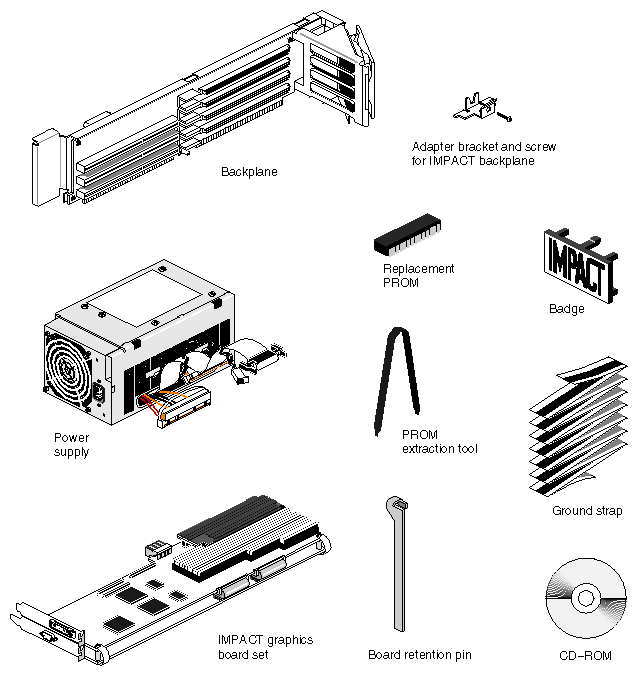
The upgrade kit (see Figure 2-1) includes but is not limited to the following:
Graphics board set (one of the following)
Indigo2 Solid IMPACT graphics board (P/N 030-0786-00x) (MG10)
Indigo2 High IMPACT graphics board set (P/N 013-1150-00x) (MG11)
Indigo2 Maximum IMPACT graphics board set (P/N 013-1149-00x) (MG21)
385-watt power supply (P/N 060-8001-00x) or 390-watt power supply (P/N 060-8021-00x)
Graphics system backplane (P/N 013-1147-00x)
Backplane bracket and screw (P/N 040-1038-00x)
Indigo2 IMPACT PROM (P/N 070-1367-007 or 070-1371-007) or later revision
PROM-removal tool (P/N 9448008)
IRIX operating system CD-ROM(s) (P/N is variable)
Graphics board set retention pin (P/N 040-1238-00x)
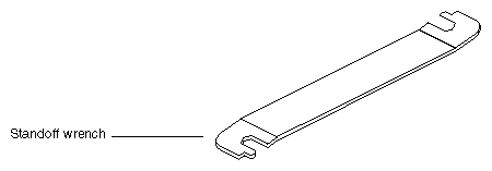
Wrench for removing board standoffs (P/N 040-8341-00x)
Indigo2 IMPACT badge (P/N 050-0204-00x)
Upgrade label (to attach to the back of the system) (P/N 024-8080-00x)
Disposable wrist strap (P/N 8050103)
RMA documents for old components
 | Note: The optional TRAM daughter board (P/N 030-0676-00x) is shipped in a separate upgrade kit. Detailed installation instructions are included in the Indigo2 IMPACT Texture Memory Option Board Installation Guide (P/N 007-3079-001) |
You need the following tools:
phillips type screwdriver
wrist strap
PROM extraction tool
You should also make sure that a CD-ROM drive is available, preferably one that is attached directly to the system (either internally or externally).
If you are not familiar with booting the IRIX miniroot and using the software installation tool inst, refer to the Software Installation Administrator's Guide.
Begin the upgrade by properly shutting down the system and powering it off. Then move to the front of the unit and remove the covers. Use the following steps:
Snap the front cover away from the top and press the power switch.
Remove the security bar (if present) and disconnect any EISA, graphics, or video cables that are connected to the system.
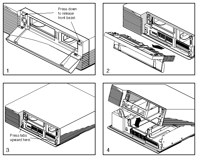
Press down on the tabs and remove the front bezel (see Figure 2-2).
Press up on the tabs at either side of the drive openings.
Pull up on the cover and lift it back and away from the chassis.
Remove the old components from the customer's Indigo2 as follows:
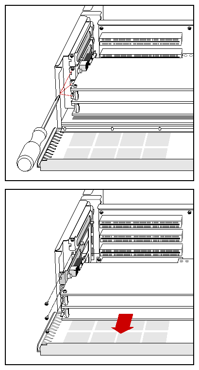
Lower the metal door that covers the GIO and EISA expansion slots, then unfasten the screws on the I/O plates that hold the graphics, EISA, or video boards to the chassis. Figure 2-3 shows a board removal example. Graphics boards, EISA, or video boards are all removed in a similar manner.
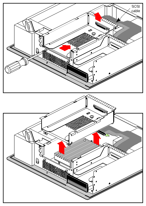
Unlatch the retaining clips and disconnect the flat flex SCSI cable from the rear of the 5-1/4 inch drive tray.
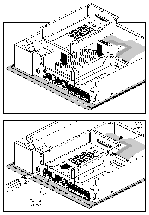
Undo the captive screws located in the lower front of the tray (see Figure 2-5). Note that if a drive is installed in the tray, you may remove it or leave it in place.
Slide the tray back to unlatch it, then lift it up and out of the system.
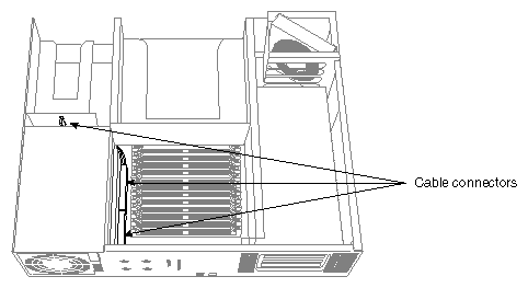
Disconnect the motherboard and system drive power supply cables as shown in Figure 2-6.
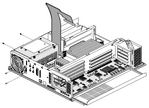
Unfasten the four screws that hold the power supply in place. Two are located on the back of the system and the other two are located on the side of the system, as shown in Figure 2-7.
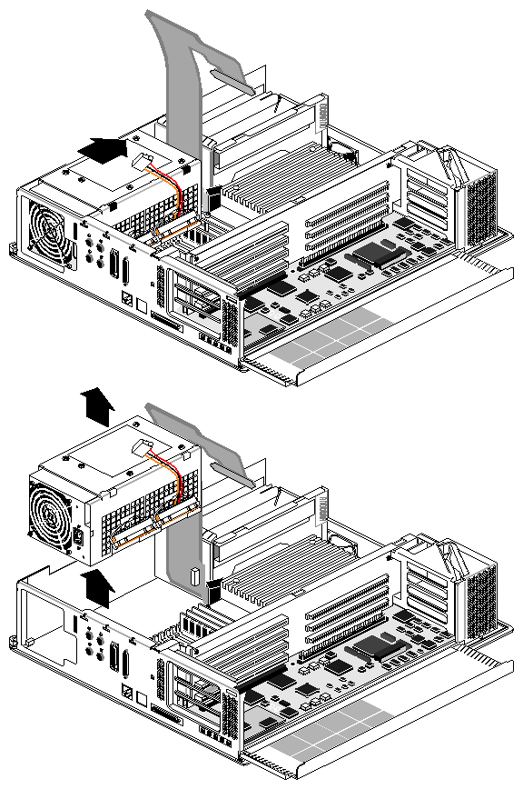
Slide the power supply toward the front of the system about 1/4 inch (approximately 6 mm), then lift it out of the chassis, as shown in Figure 2-8.
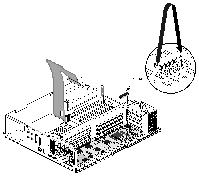
Locate the PROM on the system motherboard. See Figure 2-9.
Remove the old PROM using the tool provided in the upgrade kit.
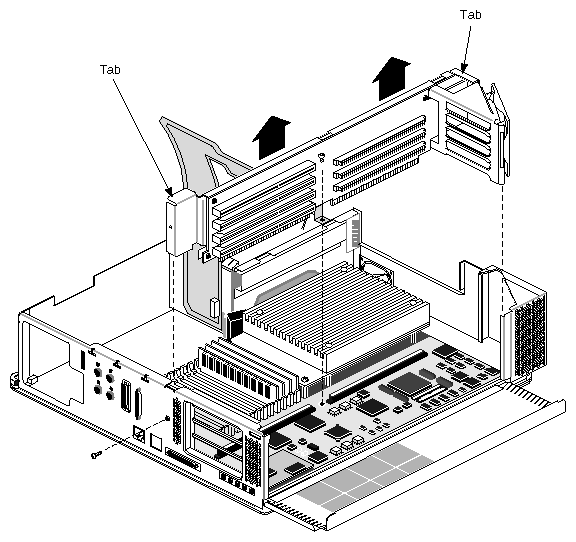
Remove the two screws that fasten the EISA/GIObus backplane to the chassis, as shown in Figure 2-10. The first screw connects the backplane to the rear sheet-metal frame of the Indigo2; the second secures the backplane to the motherboard.
Lift out the backplane and fan assembly by pulling up on the metal tabs located at either end of the backplane.
Note: Some older chassis may not have screws fastening the backplane to the chassis.
You are finished removing the old components of the system. Proceed with Section 2.2.5, "Installing the New Components."
Note: The video boards designed to work with XZ, XL, or Extreme graphics do not work with Indigo2 IMPACT graphics. Do not attempt to reinstall them with the new graphics boards.
Install the new components as follows:
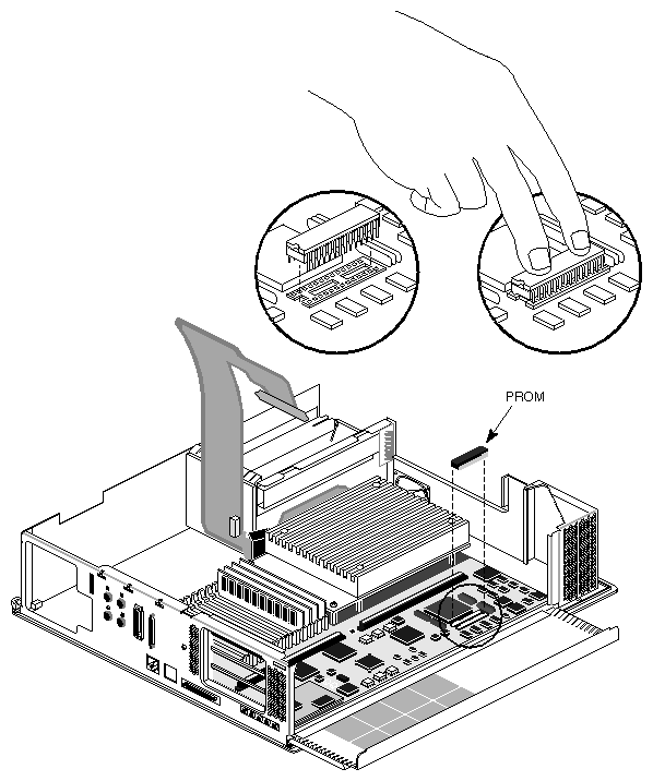
Install the new PROM on the system motherboard. See Figure 2-11.
Be sure the PROM is firmly seated.
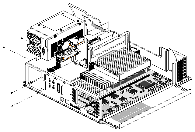
Holding the power supply in one hand, connect the power cable that attaches to the back of the system drive bay first.
Lower the power supply into the chassis as close to the disk drives as possible. Make sure that the power supply is flat against the bottom of the chassis.
Push the supply toward the back of the chassis, making sure that the metal tabs on the chassis floor engage the slots on the bottom of the power supply.
Note: If you can't lift up on the supply without lifting up the chassis, the tabs are properly engaged. Align the screw holes on the power supply with the appropriate holes on the chassis, then install and tighten the screws. See Figure 2-12.
Connect the two power cables located near the SIMM modules into the motherboard. These cables are not keyed and should be carefully aligned before pressing firmly to seat them. The side-connected power cables are not attached until the new backplane and fan assembly is installed.
Note: With some older models of the Indigo2 system, you may have difficulty sliding the power supply into position. If this happens, remove the power supply and examine the bottom of the unit. Locate the two tabs on the bottom of the power supply that attach the unit to the U-shaped slots on the bottom of the system chassis. Using a flat-bladed screwdriver, bend the two tabs outward slightly (approximately two to three millimeters) so that they protrude farther from the bottom of the power supply. This allows the tabs to slide into the U-shaped slots.
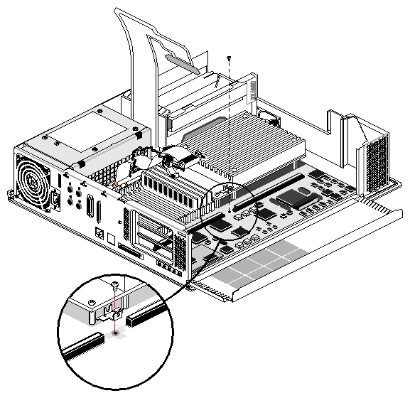
Install the new backplane adapter bracket onto the motherboard using the screw from the old backplane. Note that the "tongue" of the bracket is closest to the graphics boards, while the "forked" piece is closer to the CPU and drives. See Figure 2-13.
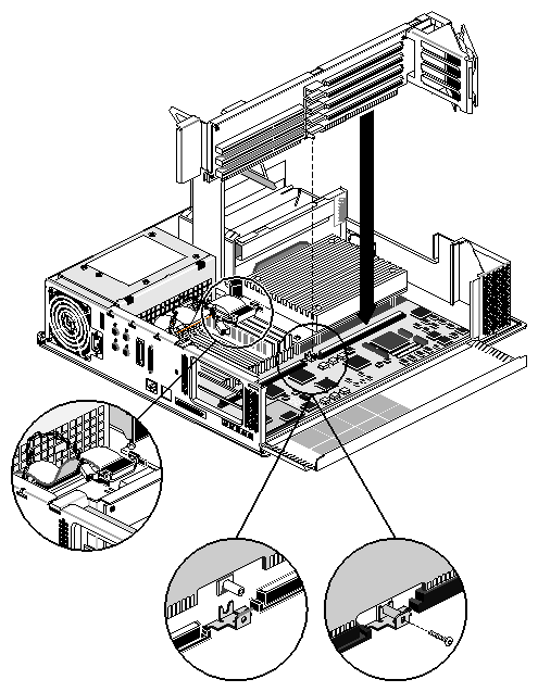
Install the new backplane by lowering it into position and pressing firmly to seat the backplane connectors in the slots on the system motherboard. See Figure 2-14.
Install the screw (from the upgrade kit) that connects the motherboard adapter bracket to the cylinder protruding from the bottom of the backplane sheetmetal. Install and tighten the screw that holds the backplane to the rear chassis sheet metal.
Unroll the two power cables from the new power supply and connect them to the new backplane.
Note: You may need to cut the cable tie that helps to secure the two power cables in place during shipping to allow you to plug in the cables.
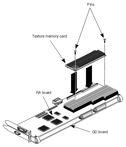
Prepare for installation of the new boards by attaching any TRAM daughter boards to their respective connectors. See Figure 2-15 for an example. See the Indigo2 IMPACT Texture Memory Option Board Installation Guide (P/N 007-3079-001) if you need detailed information.
Note: With some configurations (Indigo2 Maximum IMPACT), it may be impossible to reinstall EISA boards in the upgraded system. Only new Indigo2 IMPACT video boards work with the new graphics. Older (XL, XZ, or Extreme™) boards are not supported.
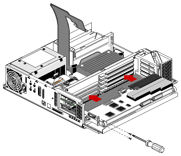
Install the graphics boards, any Indigo2 IMPACT supported video board, and any EISA boards that you removed from the system. See Figure 2-16.
Note: Always install the board set with the geometry display (GD) board in the bottom slot of the backplane. With the single-board Solid IMPACT upgrade, it is preferable to install the board into the second slot from the bottom. However, this board can fit into any available slot. Consult the Indigo2 Video for Indigo2 IMPACT Owner's Guide (P/N 007-2201-003) for specific information on installing Indigo2 IMPACT-compatible video boards.

Caution: When inserting and seating the graphics boards in the new backplane, never press on the flex connectors or cables. Always seat the boards by pushing on them near the standoffs. Be careful when holding or touching the boards not to bend any of the fine-pitch pins used on the boards. Secure each board with a screw at the upper left corner (see Figure 2-16).
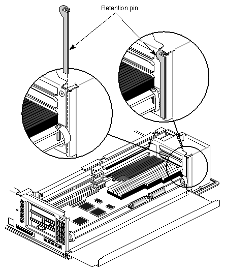
Position the board retention pin on the sheet-metal chassis next to the fan housing as shown in Figure 2-17.
Swing the metal door of the chassis upright and make sure it snaps in place.
Reinstall the 5-1/4 inch drive tray and reattach the flat SCSI cable and retention clips. When lowering the tray, keep it level, as shown in Figure 2-18, to avoid hitting the CPU module with a corner of the drive tray.
Caution: Be very careful not to damage the CPU module when reinstalling the 5-1/4 inch drive tray. The back side of the CPU module is very close to the underside of the drive tray. Before sliding the drive tray forward and locking it in place, visually inspect the clearance between the drive tray and the CPU module. (Look through the perforated metal at the bottom of the drive tray).
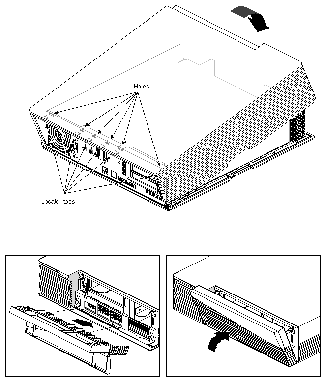
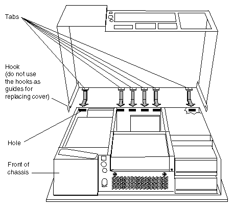
Replace the top cover, as shown in Figure 2-19. Be sure to properly align the plastic tabs in the top rear of the cover when sliding it on.
Reinstall any peripherals and attach any applicable graphics, video, or EISA cables to the system.
Note that the Indigo2 IMPACT graphics board set uses a DB-9 connector for StereoView connections rather than the previous round MINIDIN-8 for the XL, XZ, and Extreme graphics boards sets.
| Note: Always confirm that the new backplane assembly fan is working as soon as you power on the system after the upgrade. There should be noticeable air outflow at the front left corner. |
Upgrading your Indigo2 IMPACT Ready system to an Indigo2 IMPACT requires replacing the board set and connecting power cables.
Shut down the system, remove the cover, and attach the wrist strap.
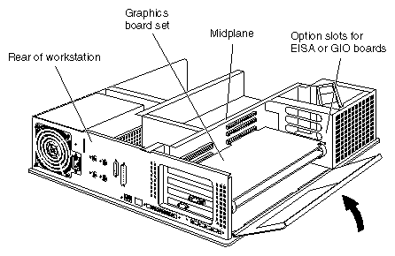
Move the workstation or position yourself so that you are facing the expansion slots, as shown in Figure 2-20.
Open the metal panel in front of the expansion slots by pulling up on the panel and lowering it.
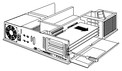
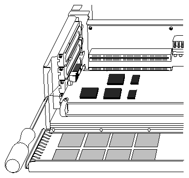
Note: If an option board is installed above your Indigo2 Extreme graphics board set, you must remove it before proceeding. Follow the procedure for removing the option board as outlined in its installation manual. Remove the screws attaching the board set to the workstation slots as shown in Figure 2-21.
The screws are located on the metal extension on the left side of each board.
Loosen each screw with the Phillips screwdriver.
Unscrew and remove the screws with your hand.
The screws are very small. If you drop a screw into the chassis, retrieve it to prevent shorting the system.
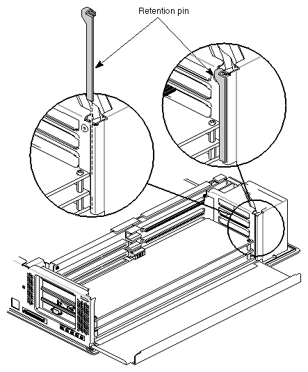
Remove the retention pin from the workstation.
Check how the retention pin rests against the front of the board set.
Grasp the retention pin on the right-front end of the board set and pull it up and off. See Figure Figure 2-22.
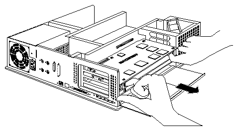
Pull the board set out of the workstation, as shown in Figure 2-23.
Turn both hands inward so that your thumbs point to the floor.
Place your index fingers behind the small metal posts on each side of the board.
Brace your thumbs against the chassis, and pull the board out of the slot. You may need to use some force.
Place the board set down on a flat, antistatic surface so the side with the chips faces up. An empty antistatic bag or a clean, dry desktop works well.
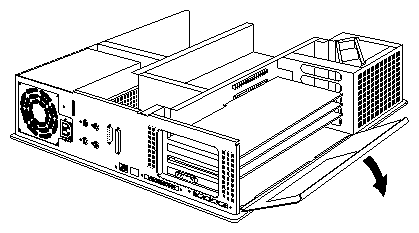
Replace the Indigo2 IMPACT board(s) in the chassis.
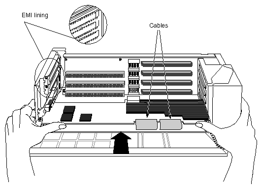
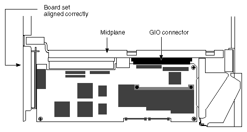
Note: Insert the board carefully so that the board edge does not catch on the EMI lining along the inner left cutout area. Make sure the EMI lining is not damaged and remains between the chassis and the graphics board's metal extension. Grasp the chassis with your fingers and push the board set into place with your thumbs. See Figure 2-24.
Push the board set into the slot until the connector on the back of the board is securely inserted to the connector on the midplane.
Note: Place pressure on the recommended board edge or standoff near the top of any board stack when reinserting the board stack into the workstation. You will need to use some force to properly seat the board stack.
Caution: As you replace the board set, do not press on the flexible cables that connect your Indigo2 IMPACT board(s). Figure 2-24. Connecting the Indigo2 IMPACT Graphics Board(s) to the Midplane (High IMPACT Version Shown)
Visually check that the boards are completely seated in their connectors when viewed from above (see Figure 2-25).
Insert and tighten the screws that hold the board set to the chassis. The screw openings are located on the metal extension on the left side of each board.
Note: You will insert one screw into your Maximum IMPACT board set. Hang the retention pin so that it sits in front of the board set, between the board set and the metal panel. The retention pin prevents the board set from moving away from the connectors (see Figure 2-27).
Note: Use the retention pin as a plumb line to determine if the board set is properly seated. If the retention pin hangs at a 90o angle to the top of the workstation, the board set is properly installed. If the pin is tilted, push in on the board set until it is properly connected.
Tip the metal panel up in front of the boards until it snaps into place (see Figure 2-28). This completes installation of the Indigo2 IMPACT graphics board(s). You can now connect the internal power cables to the midplane as shown in the new few steps.
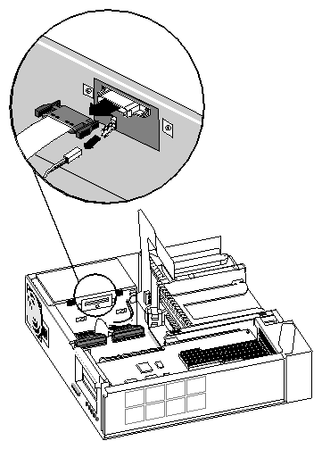
Disconnect the power supply cables from their storage site on the power supply. See Figure 2-29.
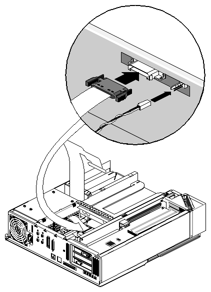
Connect the power cable and twisted-pair cable to the gold-colored midplane.
Pinch together the corrugated edges on the power cable connector, and connect it to the midplane. See Figure 2-30.
Push gently on the twisted-pair connector to connect it to the midplane.
Remove the antistatic wrist strap.
To replace the cover, and power on the system, go to the next section.
To replace the top cover, follow these steps:
Align and close the top cover (see Figure 2-31).
Face the front of the workstation.
Replace the bezel.
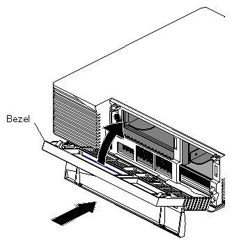
Place the tabs on the bottom of the bezel into the grooves in the front of the chassis, as shown in Figure 2-32.
Tilt the bezel up until it snaps into place.
Reinstall the lockbar if you had one installed.
Reconnect the cables to their connectors on the back of the Indigo2 IMPACT workstation.
You are ready to power on the system.
The next step in the upgrade procedure is to install IRIX 5.3 for Indigo2 All IMPACT (p/n 812-0119-0x0). You must perform this installation from the miniroot.
Follow these steps to boot the miniroot and install the newest version of IRIX:
Make sure a CD-ROM drive is attached to the system (or is available on the network). This procedure assumes you have a CD-ROM drive attached either directly to the system or across the network. See the Software Installation Administrator's Guide if you need more detailed information on booting the miniroot from a remote CD-ROM.
Power on the system.
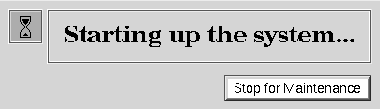
As the system comes up, you see this notifier (see Figure 2-33):
Click the Stop for Maintenance button or press the <Esc> key. The System Maintenance menu appears.
Select "Enter Command Monitor" or press 5.
At the command monitor prompt (>>), type hinv <Enter>.
Check for confirmation that the upgrade is recognized; you should see information similar to the following:
Graphics board: High Impact/TRAM option card
Type exit after confirming the upgrade.
Select "Install System Software" from the System Maintenance menu or press 2.
Load the applicable IRIX CD into the CD-ROM drive.
You should see a series of icons representing installation choices. Select the icon for the installation you are performing, for example Local CD-ROM. The miniroot begins to load.
If you wish to perform the installation from a remote CD-ROM:
Insert the CD if you have not already done so.
Select the Remote Directory icon.
Type in the name of the remote host, then click Accept or press <Enter>.
Type in the remote directory name if it is a distribution directory, then click on Accept or press <Enter>.
Click the Install button or press <Enter> and the miniroot installs.
After a while, you see the inst prompt. A default set of subsystems is selected for installation. You may wish to add or delete subsystems as required.
After you have selected the appropriate subsystems, enter go at the inst prompt.
Once all the subsystems are installed, enter quit to exit from Inst.
Type yes when asked if you want to reboot the system to multiuser mode.
Log in and enter the following command to verify that the installation worked and that the operating system is at the proper IRIX release level:
uname -a
If uname reports that the system is running the applicable level of IRIX software, the installation is successful.
If you do not encounter any problems, see Section 2.5, "Running Demos."
The new operating system eliminates a number of patches that were required for the earlier software release (IRIX 5.3 for Indigo2 IMPACT). For example, bug fixing patches 817 and 883, as well as video fixing patch 887 have been incorporated into IRIX 5.3 for All Indigo2 IMPACT. If you attempt to reinstall older patches, installation conflicts occur and cause the Inst program to mistakenly ask you to install "earlier versions" of the patch.
To determine which patches are required or no longer required, consult the product release notes, or check the Global Customer Service (GCS) patch server or the patch Web page at http://bits.csd.sgi.com/digest/patches/ or http://morpheus.corp/oasis.html. Also read the New Product Information at http://bits.csd.sgi.com/cgi-bin/bulletin_viewer.cgi
| Note: Patch 1099 (for Solid IMPACT) has been incorporated into the IRIX 5.3 for Indigo2 IMPACT release. However, patch 1157 and possibly other patches may also be required for the system. Check the web sites listed above for further information. |
To use the NTSC and PAL video formats on the Indigo2 IMPACT system, you also need to install the Indigo2 Video for IMPACT option or the Indigo2 IMPACT Video option. Do not confuse the two packages, as they have different capabilities and functions. Here is a brief description of these packages.
Indigo2 Video for IMPACT option (marketing code D9-I2V-I) is a video collaboration bundle (see Figure 2-34). This option enables you to conduct video conferences (using the Indy Cam™), output graphics to videotape, display video in a graphics window, save (capture) video to the hard disk, and also provides direct analog input/output for NTSC and PAL support.
Indigo2 IMPACT Video option (marketing code D9-I2I-VIDEO) enables real-time digital video for IMPACT (see Figure 2-35). IMPACT video provides high-quality digital video input, output and effects to help create professional video productions.
Note: This package requires an optional digital-to-analog converter for NTSC and PAL support.
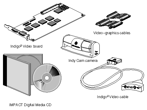
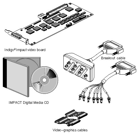
The CD IMPACT Digital Media 1.1 contains software directories to support both the Indigo2 Video for IMPACT and the Indigo2 IMPACT Video boards. The Indigo2 Video for IMPACT directory filename is impactI2V. The Indigo2 IMPACT Video directory filename is impactvid.
If you load the wrong directory, it can cause problems. For example, you may not be able to bring up the vpanel application if you load impactvid instead of impactI2V. In addition, if the wrong software image is loaded, some of the Digital Media Tools may cease to function properly and hinv will not list the video board.
To correct this problem, use the versions remove command to get rid of the wrong files (including any related patches). Afterwards, reload the operating system software and then install the correct directory.
Before turning the system over to the customer, it is highly recommended that you run the graphic demo programs to show off the enhanced video capabilities. Load the software demo CD (p/n 813-0447-00x) that ships with the upgrade and read the demo CD instructions to run the demos, as required.
Here are the final steps to complete the upgrade:
Attach the Indigo2 IMPACT badge to the front of the system. It snaps into the front grill in the lower right-hand corner.
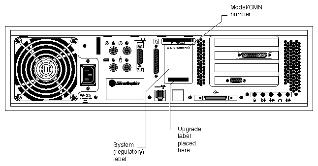
Install the upgrade label that indicates the new Silicon Graphics model number of the system. Affix the label at the rear of the system, covering part of the old label (see Figure 2-36).
If you received a new regulatory label with the upgrade, place the label as follows.
For a "full-size" label, place it over the full-size regulatory label on the rear of the workstation (see Figure 2-36).
For a "half-size" label, place it below the logos and over the lower portion of the regulatory label on the rear of your workstation (see Figure 2-36).
Determine your CMN model number. This number is required by various regulatory groups to help identify your Declaration of Conformity. You can determine your CMN number by cross-referencing the regulatory label designation (see Figure 2-36) against information contained at the following web address: http://www.sgi.com/Products/compliance/index.html.
Locate and print or save your Declaration of Conformity. Make a note of your CMN number and the date on the Declaration of Conformity here for future reference.
To run the Indigo2 IMPACT system diagnostics, continue to the beginning of Chapter 3.
| Note: Pack the old components for return shipment to Silicon Graphics. Turn to the end of Chapter 3 for details. |