This document describes the procedures used to upgrade the graphics board set in an existing Silicon Graphics Indigo2™ system to an Indigo2 IMPACT graphics system. The generic term Indigo2 is used in this document to describe both systems unless there is a specific reason to differentiate them. Note that Indigo2 IMPACT graphics were known as "Mardigras" during product development.
 | Caution: The upgrades described in this document should be performed by Silicon Graphics trained or approved field service personnel only. |
The POWER Indigo2 does not support the Indigo2 IMPACT upgrade. Do not install this upgrade into a POWER Indigo2.
The Indigo2 IMPACT graphics upgrade offers the customer direct access to next-generation desktop graphics capabilities without the expense of purchasing a new desktop system.
A list of replacement parts used with Indigo2 IMPACT graphics upgrades is shown in Chapter 2.
The Indigo2 IMPACT graphics board set uses the Geometry Engine® (GE11) Application Specific Integrated Circuit (ASIC) as one of its key performance graphics devices. The Solid IMPACT™ single-board graphics and High IMPACT™ graphics board set use only a single GE11. The Indigo2 Maximum IMPACT™ graphics board sets two GE11s.
The entry-level MG10 single-board graphics system provides the first level of IMPACT graphics support. The High IMPACT graphics system uses two standard and one optional board, and the Maximum IMPACT system uses three standard and two optional boards. Reference Table 1-1 for a summary of the configurations.
The geometry display (GD) board is the foundation for the MG11, MG14, MG21, and MG 24 graphics board sets. When the GD board is populated with a single GE11 ASIC, it is generally referred to as a GD1. If the board has two GE11s, it is called a GD2.
The GD board acts as the direct interface with the GIO bus (also known as the GIO64), which transfers data from the Indigo2 CPU board. The GD receives drawing commands and data from the host by way of the GIO backplane bus. The bus is bidirectional and runs at 33 MHz. Data from the GIO bus is fed directly to the GD by way of the HQ3 ASIC that resides on the GD board.
All vertex transformation and many of the image processing operations take place on the graphics display (GD) base board.
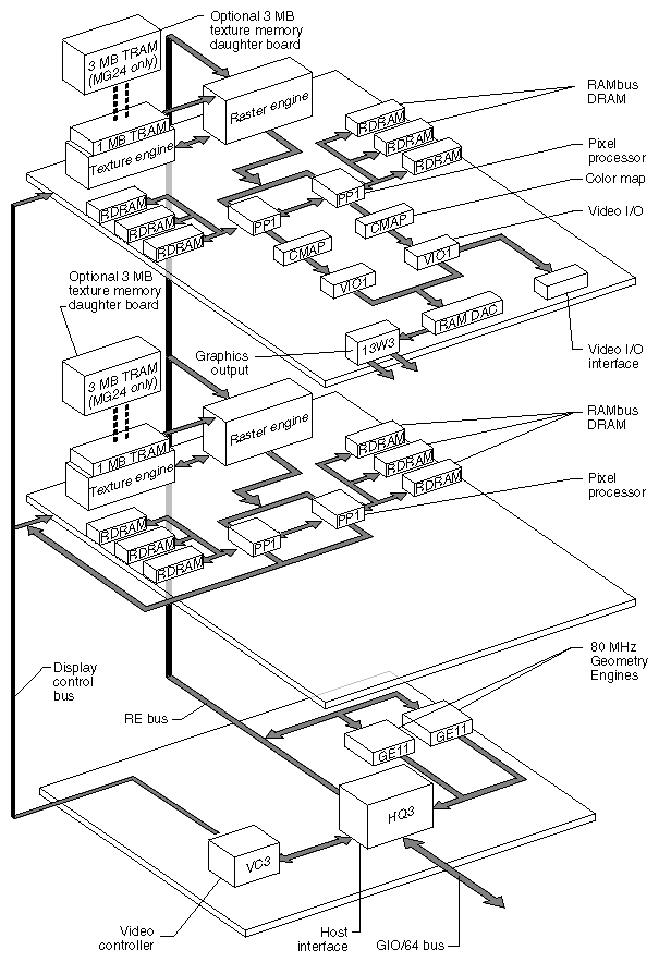
The HQ3 acts as a gatekeeper, busing data between the GE11(s), the raster A (RA) interface, and the display control bus (DCB). The DCB carries setup information to the back end components such as the RAMDAC and color map (CMAP) devices. It also communicates with the video option boards (if present). It does not carry graphics signals.
The board's GE11(s) works with a group of other graphics accelerating ASICs to provide a high-performance graphics interface in a compact board set.
The available boards in the Indigo2 IMPACT set include two raster subsystem boards, raster A (RA) and raster B (RB). These boards perform the rasterizing and double-buffering of triangles before delivery to the display subsystem. An optional 3 MB texture RAM (TRAM) daughter board is available to enhance the performance of the RA and RB boards.
 | Note: When installing an Indigo2 Maximum IMPACT graphics subsystem, if the raster A board is upgraded with a TRAM daughter board, then the raster B board must also be upgraded. You may not upgrade the TRAM on only one of the raster boards. |
Initial Indigo2 High IMPACT configurations ship with a GD board equipped with one 90 MHz GE11 ASIC. This board set is referred to as Indigo2 High IMPACT.
For additional technical and configuration information on the raster boards, read the information in the following subsections.
See Table 1-1 for a listing of Indigo2 IMPACT graphics option configurations.
Table 1-1. Indigo2 IMPACT Graphics Board Configuration Options
MG10 Solid IMPACT | MG11 Indigo2 High IMPACT | MG14 Indigo2 High IMPACT | MG21 Indigo2 Maximum IMPACT | MG24 Indigo2 Maximum IMPACT |
|---|---|---|---|---|
Single-board graphics with one GE11 | Raster A (RA) board with 1 MB of texture RAM | Raster A (RA) board with 1 MB of texture RAM | Raster A (RA) board with 1 MB of texture RAM | Raster A (RA) board with 1 MB of texture RAM |
Single-board graphics with one 90 MHz GE11 | Geometry Display board (GD) with one 90 MHz GE11 | One texture daughter board with 3 MB of TRAM | Raster B (RB) board with 1 MB of texture RAM | Raster B (RB) board with 1 MB of texture RAM |
|
| Geometry Display board (GD) with one 90 MHz GE11 | Geometry Display board (GD) with two 80 MHz GE11s | 2 optional texture daughter boards with 6 MB of TRAM |
|
|
|
| Geometry Display board (GD) with two 80 MHz GE11s |
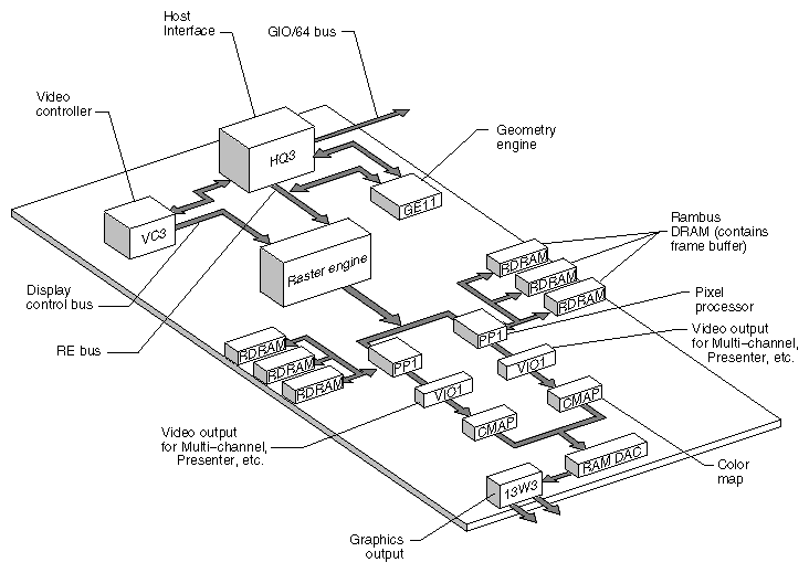
The Solid IMPACT or (MG10) graphics option is a single-board implementation of the IMPACT graphics architecture. A single GE11 is used and the geometry display, raster manager, and HQ circuitry are all on the same board. The 13W3 and StereoView™ connectors are included on the board.
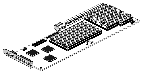
An MG10 IMPACT system cannot use additional raster boards or TRAM daughter boards. Figure 1-1 shows the MG10 single-board IMPACT graphics board. See Figure 1-2 for a basic functional block diagram of the MG10.
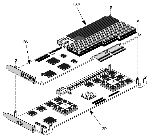
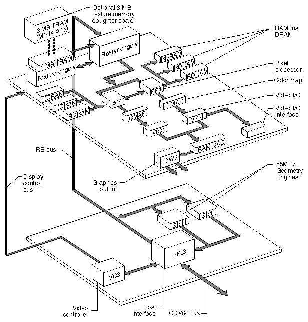
The GD board combined with the raster A board makes up the basic Indigo2 High IMPACT graphics set, also known as the MG11. An optional 3 MB texture RAM daughter board installs on the raster A board. It provides enhanced graphics texturing. Adding the optional 3 MB texture RAM daughter board designates the board set as an MG14.
The raster A board houses a single raster subsystem, a display subsystem, a video I/O multiplexer, a texture engine, and 1 MB of texture engine RAM (TRAM). Optionally, it can have a total of 4 MB of TRAM (using a 3 MB TRAM daughter board).
Figure 1-3 shows a two-board graphics set. See Figure 1-4 for an overall functional block diagram of the MG11 or MG14 graphics implementation.
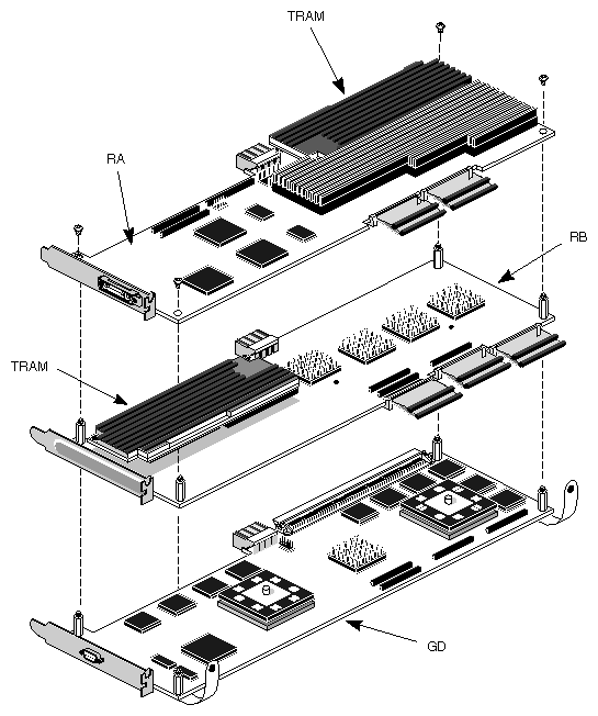
Implementation of an MG21 or 24 graphics board set requires the dual 80 MHz GE11 geometry display (GD) board plus the addition of the raster A board and raster B board.
This combination of raster A and B boards with the GD board is the basic Indigo2 Maximum IMPACT graphics set, also known as the MG21. Using an optional 3 MB texture RAM daughter board on raster A and raster B offers enhanced graphics texturing (also known as MG24).
| Note: When equipping the raster boards with extra TRAM, raster A and raster B must both use the TRAM daughter boards. You may not upgrade only one of the two raster boards with a TRAM daughter board. |
The raster A board houses a single raster subsystem, a display subsystem, a video I/O multiplexer, a texture engine, and 1 MB of texture RAM (TRAM). The raster A board provides the 13W3 monitor connector.
The raster B has a single raster subsystem, a texture engine, and 1 MB of texture RAM standard.
Figure 1-5 shows a three-board graphics set with optional TRAM daughter boards. See Figure 1-6 for an overall functional block diagram of the MG21 or MG24 graphics implementation.
The following subsections discuss major components that make up the Indigo2 IMPACT graphics board set. Some of the components are optional, and not every system has all of them. Consult Table 1-1 for information on the hardware included with each version of the graphics board set.
The HQ3 ASIC has a 50 MHz internal clock and a 100 MHz interface to the GE11(s). The GIO64 interface to the system motherboard runs at 33 MHz. The HQ3 deals with both graphics primitives (lines and triangles) and pixels. It supports transfer of all OpenGL® pixel types. It can reformat pixel line areas for optimal Geometry Engine and raster engine processing.
The HQ3 supports the following types of high-speed transfers:
Straight through, host-to-raster-engine pixel reads and writes.
Host-to-Geometry Engine and raster engine operators and format conversions.
Raster-engine-to-Geometry Engine pixel operations on screen-to-screen copies.
Raster engine or Geometry Engine to host transfers for pixel read reformatting.
The HQ3 also acts as an interface for the GE11(s). By using an internal RAM-based microcode sequencer, the HQ3 can:
parse the GE11 instruction stream into primitives for distribution to the GE11(s)
track GL attributes and update the GE11(s) as needed
normalize 8- or 12-bit color values
control REbus ownership and arbitration
reformat GIO data into raster engine register formats
GE11 ASIC(s) are installed on the geometry display (GD) board in the Indigo2 IMPACT. The GE11s used have internal first-in-first-out (FIFO) buffers. They each also use static random access memories (SRAMs). Each GE11 ASIC on the GD board uses
two 64Kx18 data SRAMs
four 64Kx18 SRAMs for microcode
The GE11 has an internal microcode sequencer, but it executes by way of an external microcode RAM. Direct access to external RAM is also used for storing look-up tables and context information.
Other GE11 internal features include
three floating point unit and integer cores
a 2Kx32 main internal RAM
instruction cache TAG RAM
a 32-bit wide instruction block
a branch table cache
32x32 bit data registers
a 16x32 bit address register file
precision floating point number to integer converter
128x32 bit output buffer RAM used for passing information to the raster engine
Each raster engine (RE) ASIC works with two pixel processor (PP1) ASICs, and six RAMbus Dynamic Random Access Memory (RDRAMs).
The GE11 feeds geometry, color, and texture information for triangles, blocks, lines, and points to the RE ASIC. Computation of pixel primitives and their associated parameters are passed on to the rendering subsystem. Increasing the number of raster engines increases the fill rate for all spans. The Indigo2 IMPACT graphics system is limited to a maximum of two raster engines (one on the raster A board and one on the raster B board).
The texture engine (TE) provides texturing capabilities to the graphics rendering raster engine (RE) discussed in the previous subsection. The TE is an enhancement to the graphics renderer ASIC. Only one TE is used with each RE.
| Note: The Solid IMPACT board does not contain a TE ASIC and does not have hardware texturing capabilities. |
Each texture engine uses one or (optionally) four texture RAM (TRAM) ICs. To add the three optional texture RAM devices to the raster board requires the installation of an optional TRAM daughter board.
Each raster board can have one optional 3 MB TRAM daughter board installed.
Note that you cannot configure a system that uses one raster board with the optional 3 MB TRAM daughter board and a second that has only 1 MB of TRAM.
The HRBE consists of
a VC3 high-resolution timing display generator (on the GD board)
two VIO1 video interface ASICs (on the raster board)
two color map ICs (CMAPs) (on the raster board)
one RAMDAC digital-to-analog converter (on the raster board)
one 13W3 video connector (on raster A)
The Indigo2 IMPACT graphics system consumes more power and dissipates approximately 300 BTUs per hour more heat than previous Indigo2 XZ, XL, and Extreme graphics systems. However, there are no special additional site requirements for power and no additional site requirements for cooling.
All other environmental site requirements, including humidity, altitude, temperature, and vibration are unchanged.
Some EISA option boards may not yet be supported. Either you or the customer may wish to verify with Silicon Graphics whether or not a particular option board is supported. Also note that the Indigo2 IMPACT backplane has one less EISA connector available than previous Indigo2 backplanes.
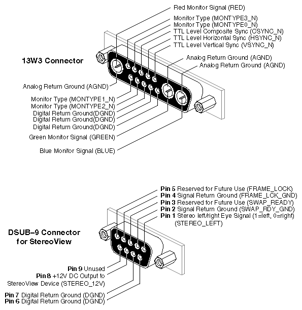
The raster A board has a 13W3 monitor connector, and the GD board has a 9-pin StereoView connector. Figure 1-7 shows the connectors and their pinouts.
There are three different versions of the power supply for the Indigo2. Each version has different graphics support capabilities (see Table 1-2 and Figure 1-8).
Table 1-2. Indigo2 Power Supply Versions
Power Supply P/N | Comments |
|---|---|
9430814 (older-style, early Indigo2 power supply) | Supports Extreme, XZ, and XL graphics, but does not support Indigo2 IMPACT graphics. This power supply must be replaced by 060-8001-00x or 060-0021-00x for the IMPACT upgrade. |
060-8001-00x (385-watt first replacement power supply) | Supports Indigo2 IMPACT graphics and also supports all dual-head configurations, except for the Solid and Maximum IMPACT combination in an R4400 Indigo2 (see Table 1-3). |
060-0021-00x (390-watt second replacement power supply) | Supports Indigo2 IMPACT graphics and all dual-head configurations (see Table 1-3). |
The new power supply is mechanically similar to previous revisions. However, it provides higher current ratings and also has a direct power connection to the new Indigo2 IMPACT graphics backplane. The increase is required for the Indigo2 IMPACT and other graphics upgrades.
| Note: The IMPACT graphics boards use mainly 3.5 V technology rather than 5 V. |
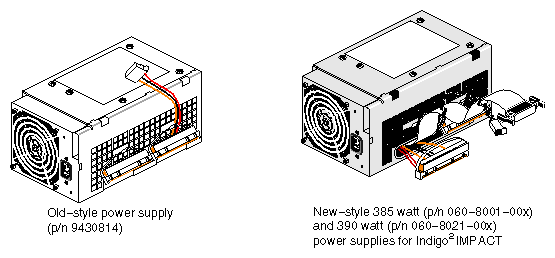
| Note: The 385-watt (first replacement) power supply (p/n 060-8001-00x) and the 390-watt (second replacement) power supply (060-0021-00x) look nearly identical. See Table 1-3 for a list of support differences between the two power supplies. |
Table 1-3. Power Supplies and Dual-Head IMPACT Support
Dual-Head IMPACT configuration | Supported by first replacement power supply (p/n 060-8001-00x)? | Supported by second replacement power supply (p/n 060-0021-00x)? |
|---|---|---|
Two Solid heads | Yes | Yes |
One Solid and one High head | Yes | Yes |
Two High heads | Yes | Yes |
One Solid and one Maximum head | No | Yes |
| Note: Only one MG21 or MG24 (Maximum) three-board set can be installed into an Indigo2 at a time, so you can never have a dual-head Indigo2 system with two Maximum IMPACT board sets. The Indigo2 IMPACT has only four available graphics board slots. |
The PROM on the IP22 motherboard can be accessed only after removing existing graphics, EISA, and video boards. See Section 2.2.4, "Removing the Old Components" in Chapter 2.