This chapter describes how the IRIS HIPPI light-emitting diodes (LEDs) behave.
The lRIX HIPPI board has the following LEDs, which are described in separate sections below:
one green and one yellow, controlled by the firmware
two small red, controlled by the board's processor and source clocks
eight red, controlled by the destination channel (AMCC 2021 component)
eight red, controlled by the source channel (AMCC 2020 component)
The green and yellow LEDs are controlled by the IRIS HIPPI board's firmware.
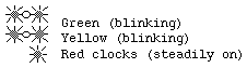
The yellow and green LEDs both blink steadily when there is power to the board and the UNIX initialization scripts the have not run to completion. Once the initialization process is complete, the yellow LED is off.
The green LED blinks steadily when there is power to the board and the board's initialization procedures have successfully brought the board into operation.
The yellow LED blinks alone when there is a problem. If the IRIS HIPPI board's firmware fails, the firmware attempts to determine the reason for the failure and to communicate the reason by blinking a code on the yellow LED. The codes are summarized in Table 3-3.
See sections 3.6 (normal operation) and 3.7 (problematic behavior) for full descriptions of the behavior for these LEDs.
The two small red LEDs labelled PCLK and SCLK are steadily on when the clocks for the respective components are functioning. The LED labelled PCLK is for the IRIS HIPPI board's processor (AMD 29030 component); the one labelled SCLK is for the source component (AMCC 2020 component).
If either of these LEDs is off, the associated component is not operational and the IRIS HIPPI board is dysfunctional, in which case you should contact the Silicon Graphics Technical Assistance Center.
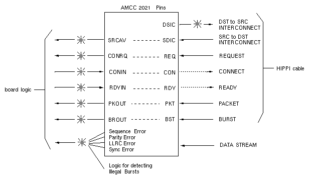
Each of the eight red destination LEDs blinks to indicate a particular event on the IRIS HIPPI board. Figure 3-1 describes what one blink of each LED means. Figure 3-1 illustrates the events that cause each LED to blink. Some of the events are the assertion of a HIPPI-PH signal as detected on one of the AMCC 2021 pins, others are the assertion of an input pin from the IRIS HIPPI board's logic.
Label on | Description of LED |
|---|---|
DSIC | 2021's DST to SRC Interconnect output pin. When this LED is on, the IRIS HIPPI board's destination is online and asserting its HIPPI-PH Destination-to-Source INTERCONNECT signal. It is not in test mode. That is, this end (the destination) of the link is available for "action." |
SRCAV | 2021's Source Available (SRCAV) output pin. When this LED is on, the other end is online and asserting its HIPPI-PH Source-to-Destination INTERCONNECT signal. That is, the other end of the link is available for "action." |
CONRQ | 2021's Connect Request (CONRQ) output pin. When this LED is on, the 2021 is detecting an asserted HIPPI-PH connection REQUEST signal, indicating that a HIPPI end source is requesting that a connection be opened. |
CONIN | 2021's Connect In (CONIN) input pin. When this LED is on, the firmware is programming the 2021 to assert the HIPPI-PH CONNECT (response) signal. This indicates that the board has accepted a connection request. When both CONRQ and CONIN LEDs are on, a connection is open. |
RDYIN | 2021's Ready In (RDYIN) input pin. When this LED is on, the firmware is telling the 2021 to send (or store up, if there is not an active connection) a HIPPI-PH READY pulse. Each blink increments the destination's READY counter by one and, if there is an open connection, causes a READY pulse to be sent to the source. There is a 1.5–millisecond pulse stretcher on this LED to ensure that the blink is visible. |
PKOUT | 2021's Packet Out (PKOUT) output pin. When this LED is on, the 2021 is detecting an asserted HIPPI-PH PACKET signal. This indicates that the source is sending a packet. |
BROUT | 2021's Burst Out (BROUT) output pin. When this LED is on, the 2021 is detecting an asserted HIPPI-PH BURST signal. This indicates that the source is sending a burst. |
ERROR | 2021's Error output pin, indicating that one of the following events occurred: 2021-reported Sequence Error There is a 1.5–millisecond pulse stretcher on this LED to ensure that the blink is visible. |
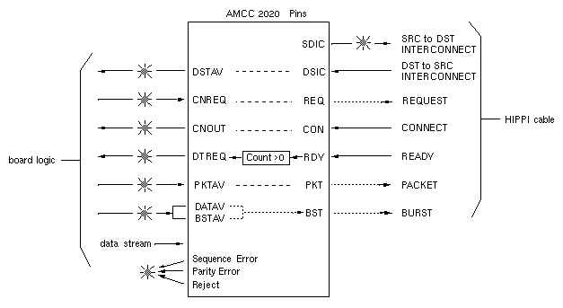
Each of the eight red source LEDs blinks to indicate a particular event on the IRIS HIPPI board. Table 3-2 describes what one blink of each LED means. Figure 3-2 illustrates the events that cause each LED to blink. Some of the events are the assertion of a HIPPI-PH signal as detected on one of the AMCC 2020 pins; others are the assertion of an input pin from the IRIS HIPPI board's logic.
Label on | Description of LED |
|---|---|
SDIC | 2020's SRC to DST Interconnect output pin. When this LED is on, the IRIS HIPPI board's source is online and asserting its HIPPI-PH Source-to-Destination INTERCONNECT signal. It is not in test mode. That is, this end (the source) of the link is available for "action." |
DSTAV | 2020's Destination Available (DSTAV) output pin. When this LED is on, the other end is online and asserting its HIPPI-PH Destination-to-Source INTERCONNECT signal. That is, the other end of the link is available for "action." |
CNREQ | 2020's Connect Request (CNREQ) input pin. When this LED is on, the host/firmware is telling the 2020 to take the provided I-field and assert the HIPPI-PH connection REQUEST signal. The 2020 is probably asserting the REQUEST signal. |
CNOUT | 2020's Connect Out (CNOUT) output pin. When this LED is on, the 2020 is detecting an asserted HIPPI-PH CONNECT signal, indicating that the connection to the destination is open. |
DTREQ | 2020's Data Request (DTREQ) output pin. When this LED is on, the destination is waiting for more data. This LED is on whenever there is an open connection and the source has received at least one READY signal for which it has not yet sent a burst (that is, the source's READY counter is greater than zero). There is a 1.5–millisecond pulse stretcher on this LED to ensure that the blink is visible. |
PKTAV | 2020's Packet Available (PKTAV) input pin. When this LED is on, the firmware is programming the 2020 to send a packet. If it can (for example, if a connection is open), the 2020 is asserting the HIPPI-PH PACKET signal on the HIPPI channel. |
BSTAV | 2020's Burst Available (BSTAV) and Data Available (DATAV) input pins. When this LED is on, the board has data to send. If it can, the 2020 will assert the HIPPI-PH BURST signal on the HIPPI channel. |
ERROR | One of the following events occurred: There is a 1.5–millisecond pulse stretcher on this LED to ensure that the blink is visible. |
The LED combinations described in this section occur during normal operation.
 |
The board has not been initialized yet. This LED behavior is normal after a system reset and until the UNIX initialization scripts run to completion.
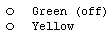 |
For a very short time during startup, both LEDs are off while new firmware is downloaded onto the board.
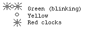 |
The board has been initialized successfully.
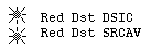 |
The physical link is intact between the IRIS HIPPI board's destination and the switch or, if no switch exists, the other endpoint. Both ends of the physical link are online, not in test mode, and ready for action.
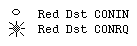 |
A source endpoint is attempting (requesting) to open a connection. The IRIS HIPPI board's firmware has not yet accepted the connection. This condition should be brief, unless you have configured the board to reject all connection requests; lengthy or frequent occurrences indicate a problem (as explained in Section 3.7, "Troubleshooting with LEDs").
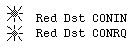 |
A connection is open. Both endpoints are ready for a data transfer.
 |
The firmware is telling the IRIS HIPPI board that the HIPPI subsystem is ready to accept data. This condition is not related to nor dependent on an open connection or a physical link.
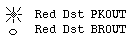 |
The source is sending a packet (that is, the PACKET line is currently asserted). Data are not being transmitted currently.
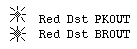 |
The IRIS HIPPI board is currently accepting a burst of data.
 |
The IRIS HIPPI board's destination is not encountering any HIPPI errors on the incoming channel.
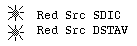 |
The physical link is intact between the IRIS HIPPI board's source and the switch or, if no switch exists, the other endpoint. Both ends of the physical link are online, not in test mode, and ready for action.
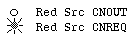 |
The IRIS HIPPI firmware is asking the board's source to open a connection. If the source channel's DSIC and DSTAV LEDs are on, the IRIS HIPPI board should be requesting the connection (that is, asserting the REQUEST line). The destination endpoint has not yet accepted the connection. This condition should be very short-lived. If the CNOUT LED fails to turn on, there is a problem, as explained in Section 3.7, "Troubleshooting with LEDs."
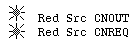 |
A connection is open. Both endpoints are ready for a data transfer.
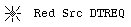 |
The IRIS HIPPI board has at least one unused READY from the destination.
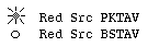 |
The source channel is ready to transmit. Data are not being transmitted currently.
 | Note: PKTAV normally remains on after a connection is terminated. This does not indicate a problem. |
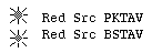 |
The IRIS HIPPI board is currently transmitting a burst of data.
 |
The IRIS HIPPI board's source is not encountering any HIPPI errors on the outgoing channel.
 |
Power has been turned on to the IRIS HIPPI board, and no connection has been setup as yet. When the first connection request is sent, this LED clears.
The LED combinations described in this section indicate abnormal operation.
 |
Indicates either no power to the IRIS HIPPI board or a malfunction of the IRIS HIPPI board.
Do the following steps to remedy this problem. After each step, check to see if the problem has been resolved before performing the next step.
Verify that the system has power.
If the system has power, verify that the IRIS HIPPI board is properly seated into its VMEBus slot and that the power modules for that VMEBus slot are functional. Alternatively, you might install the IRIS HIPPI board into a VME slot that is known to be functional in order to test the board.
Reboot the system to restart the IRIS HIPPI board.
If the problem persists, the IRIS HIPPI board may be dysfunctional. Contact the Silicon Graphics Technical Assistance Center.
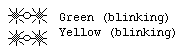 |
There is power to the board, but the board has not been initialized. For the first few seconds during startup, this behavior is normal; however, when the UNIX initialization scripts complete, the yellow LED should turn off. If both LEDs continue to be on for more than 2 minutes, either the driver has not initialized the board or the board is dysfunctional.
| Note: Do the following steps to remedy this problem. After each step, check to see if the problem has been resolved before performing the next step. |
Using the command line shown below, verify that the operating system includes the IRIS HIPPI driver. If there are entries for hippi, the operating system has been built to include IRIS HIPPI. The board may be dysfunctional. Contact Silicon Graphics' Technical Assistance Center. If there are no entries for the IRIS HIPPI driver, continue to the next step.
% grep hippi /usr/var/sysgen/master.c
Verify that the IRIS HIPPI software has been installed, using the versions command (as shown below). If the IRIS HIPPI software is not installed, follow the instructions in the IRIS HIPPI Release Notes to install it. If the software is installed, continue to the next step.
% versions hippi
Use the autoconfig command to build a new operating system (IRIX kernel) that includes the IRIS HIPPI driver. Then, reboot the system to start using the new operating system.
# /etc/autoconfig
....
# /etc/reboot
If the problem persists, the IRIS HIPPI board may be dysfunctional. Contact the Silicon Graphics Technical Assistance Center.
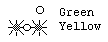 |
There is power to the board, but the board has become dysfunctional. If the IRIS HIPPI board's firmware has failed, it attempts to determine the reason for the failure and to communicate the reason by blinking a code on the yellow LED. The code is a number of blinks. The code is repeated in the following manner: the code, a pause, the same code, a pause, and so on. The codes are summarized in Table 3-3.
Reboot the system to restart the IRIS HIPPI board.
If the problem persists, determine the reason for the failure from the code that the yellow LED is blinking, then, contact the Silicon Graphics Technical Assistance Center.
Table 3-3. Yellow LED Codes for Firmware Failure
Number of Yellow LED Blinks | Reason for Failure |
|---|---|
1 | Software failure |
2 | Bad interrupt |
3 | Source memory test failed |
4 | Destination memory test fail |
5 | Flash EEPROM checksum error |
6 | Debug interrupt |
7 | Trap 1 failure |
8 | Onboard CPU (29030) bus error failure |
This section describes abnormal behavior for the destination channel.
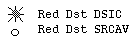 |
Indicates that the IRIS HIPPI board's destination channel is functional but that there is a malfunction somewhere between the board's destination AMCC 2021 component and the other end of the physical link.
Do the following steps to remedy this problem. After each step, check to see if the problem has been resolved before performing the next step.
Verify that the system at the other end (that is, a port at a switch or a network interface controller) is functional and online.
Use the hiptest utility and a loopback link to verify that this destination channel can receive data. (This procedure is documented in the IRIS HIPPI Administrator's Guide.) Alternatively, connect the destination channel to a different known-to-be-functional source endpoint. When the link to a functional source is installed, the SRCAV should turn on.
If you are using another HIPPI source endpoint instead of the loopback link, verify that the source and destination cables are not swapped. The destination must be connected to a source (or OUT).
Along the entire physical link, verify that all the HIPPI cable connectors are firmly seated. Be sure to check the internal connections to the IRIS HIPPI board as well as the external connections at the I/O panel.
Attach the external HIPPI cable directly to the IRIS HIPPI board. Disconnect the HIPPI cable from the destination connector on the I/O panel, open the I/O panel, disconnect the internal cable to the IRIS HIPPI board's connector, and connect the external cable directly to the IRIS HIPPI board's destination connector.
One by one, replace each of the cables between the IRIS HIPPI board's destination connector and the source on the other end of the physical link. Use cables that are known to be functional.
If the problem persists, the IRIS HIPPI board may be dysfunctional. Contact the Silicon Graphics Technical Assistance Center.
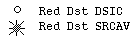 |
Indicates that the physical link and the system at the other end of the physical link are functional, but the IRIS HIPPI board has a malfunction. The problem may be as simple as the DSIC or SRCAV LED being broken, but it is also possible that the IRIS HIPPI board is dysfunctional.
Do the following steps to remedy this problem. After each step, check to see if the problem has been resolved before performing the next step:
At the other end (the source) of the physical link, check if the incoming Destination-to-Source INTERCONNECT signal is observed (asserted). If it is, the IRIS HIPPI board's DSIC LED is erroneously off.
At the other end (the source) of the physical link, check if the system is asserting its Source-to-Destination INTERCONNECT signal. If it is not, the IRIS HIPPI board's SRCAV LED is erroneously on.
Use hinv to verify that the IRIS HIPPI board has been located during startup. If the board is not listed, it is possible that the FMezz card, the IRIS HIPPI board, or the FCI cable is loose or dysfunctional.
Verify that the FCI cable between the FMezz board and the IRIS HIPPI board is firmly seated at both of its connectors.
Replace the FCI cable with a cable that is known to be functional.
Reboot the system to restart the board.
Shutdown the system and reinstall the IRIS HIPPI product (FMezz board and IRIS HIPPI board), taking extra precautions to seat the boards firmly into their connectors/backplanes. (Alternately, attach the IRIS HIPPI board's FCI cable to a different FMezz board, then reboot.)
Contact the Silicon Graphics Technical Assistance Center.
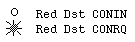 |
A source endpoint is attempting (requesting) to open a connection and the IRIS HIPPI board's firmware is not accepting the connection. The IRIS HIPPI board may be configured to reject all connection requests, or it may be dysfunctional.
Do the following to remedy this problem. If the problem persists, contact the Silicon Graphics Technical Assistance Center.
Use the hipcntl command to configure the board to accept incoming connection requests:
# hipcntl accept
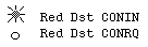
Indicates a malfunction of the board's firmware or hardware.
Reboot the system to download new firmware. If the problem persists, contact the Silicon Graphics Technical Assistance Center.
This section describes abnormal behavior for the source channel.
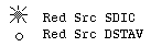 |
Indicates that the IRIS HIPPI source channel is functional but that there is a malfunction somewhere between the board's AMCC 2020 component and the other end of the physical link.
Do the following steps to remedy this problem. After each step, check to see if the problem has been resolved before performing the next step.
Verify that the system at the other end (that is, a port at a switch or a network interface controller) is functional and online.
Use the hiptest utility and a loopback link to verify that this source channel can send data. (This procedure is documented in the IRIS HIPPI Administrator's Guide.) Alternatively, connect the source channel to a different known-to-be-functional destination endpoint. When the link to a functional destination is installed, the DSTAV should turn on.
If you are using another HIPPI destination endpoint instead of the loopback link, verify that the source and destination cables are not swapped. The source must be connected to a destination (or IN).
Along the entire physical link, verify that all the HIPPI cable connectors are firmly seated. Be sure to check the internal connections to the IRIS HIPPI board as well as the external connections at the I/O panel.
Attach the external HIPPI cable directly to the IRIS HIPPI board. Disconnect the HIPPI cable from the source connector on the I/O panel, open the I/O panel, disconnect the internal cable to the IRIS HIPPI board's connector, and connect the external cable directly to the IRIS HIPPI board's source connector.
One by one, replace each of the cables between the IRIS HIPPI board's source connector and the destination on the other end of the physical link. Use cables that are known to be functional.
If the problem persists, contact the Silicon Graphics Technical Assistance Center.
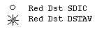 |
Indicates that the physical link and the system at the other end of the physical link are functional, but the IRIS HIPPI board has a malfunction. The problem may be as simple as the SDIC or DSTAV LED being broken, but it is also possible that the IRIS HIPPI board is dysfunctional.
Do the following steps to remedy this problem. After each step, check to see if the problem has been resolved before performing the next step.
At the other end of the physical link (the destination), check if the incoming Source-to-Destination INTERCONNECT signal is observed (asserted). If it is, the IRIS HIPPI board's SDIC LED is erroneously off.
At the other end of the physical link (the destination), check if the system is asserting its Destination-to-Source INTERCONNECT signal. If it is not, the IRIS HIPPI board's DSTAV LED is erroneously on.
Use hinv to verify that the IRIS HIPPI board has been located during startup. If the board is not listed, it is possible that the FMezz card, the IRIS HIPPI board, or the FCI cable is loose or dysfunctional.
Verify that the FCI cable between the FMezz board and the IRIS HIPPI board is firmly seated at both of its connectors.
Replace the FCI cable with a cable that is known to be functional.
Reboot the system to restart the board.
Shutdown the system and reinstall the IRIS HIPPI product (FMezz board and IRIS HIPPI board), taking extra precautions to seat the boards firmly into their connectors/backplanes. (Alternately, attach the IRIS HIPPI board's FCI cable to a different FMezz board, then reboot.)
If the problem persists, contact the Silicon Graphics Technical Assistance Center.