This chapter describes how to install the IRIS HIPPI network interface controller hardware into a CHALLENGE™ or Onyx™ server or supercomputer. There is a separate section for each of the following platforms:
CHALLENGE L Deskside
CHALLENGE XL Rackmount
Onyx Deskside
Onyx Rackmount
This section describes the steps for installing the IRIS HIPPI network product into a CHALLENGE L Deskside server. The CHALLENGE L Deskside platform supports up to four IRIS HIPPI boards.
Before starting the installation, prepare yourself and the equipment by following the instructions below.
Verify that the IRIS HIPPI package is complete. It should contain the items listed in Table 2-1.
Table 2-1. IRIS HIPPI Package Contents
Item | Quantity |
|---|---|
Short FCI mezzanine board | 1 |
HIPPI board | 1 |
Teflon-covered FCI (flat cable interface) cable assembly | 1 |
Internal HIPPI cable assembly | 1 |
Screws for attaching mezzanine board | 4 |
Labels with adapter IDs | 3 sheets |
CD-ROM with software (including online release notes) | 1 |
Documentation: |
|
If anything is missing, do not proceed with the installation. Contact the customer or the customer's salesperson.
Follow the instructions in this section to prepare the CHALLENGE L Deskside system for installation.
 | Caution: This equipment is extremely sensitive and susceptible to damage by electrostatic discharge (ESD), a spark caused by the buildup of electrical static potential on clothing and other material. You must use proper ESD preventive measures as explained in the "Safety" section of the CHALLENGE/Onyx Deskside Installation Instructions. |
Verify that the IRIX operating system is the correct version for this IRIS HIPPI release using the command below. Do not proceed until the correct version of IRIX is installed, as described in the IRIS HIPPI Release Notes.
% versions eoe1
I  eoe1  date  Execution Only Environment 1, version
Verify that the file system is backed up.
Optional, but recommended, step.
Install the IRIS HIPPI software, and do the required configuration steps. Step-by-step instructions are provided in the IRIS HIPPI Release Notes and the IRIS HIPPI Administrator's Guide. When the software is installed and configured, continue with the next step in these instructions.
Note: You cannot verify successful installation of the board until the software is installed. If you choose not to install the software now, you will need to do so after the board has been installed. Shut down the system by turning the key on the System Controller panel (located at the front) to OFF. Wait a minute for the system to shut down, then switch the circuit breaker on the back to OFF.

Warning: Failure to turn off the circuit breaker may result in electrical shock. Failure to wait for the system to shut down may cause irreparable damage to system components or data. Open the front door and pull down the I/O panel in the front of the chassis to expose the VMEBus slots and IO4 boards.
To install the IRIS HIPPI network hardware, you need to locate two available slots in the CHALLENGE chassis: one mezzanine slot (position) and one VMEBus slot. Table 2-2 lists the slots from which you can select. It is recommended that the mezzanine and VMEBus slots be as close to each other as possible because the FCI cable will connect them. However, the FCI cable is long enough to accommodate any boards in a properly configured CHALLENGE Deskside system.
Table 2-2. Slots for IRIS HIPPI Installation in CHALLENGE Deskside System
Slots Required | Slots That Can Be Used |
|---|---|
Short mezzanine slot | Upper or lower mezzanine slot on an IO4 board in slot 5, 4, or 3 |
VMEBus slot | Slot 7, 8, 9, 10, or 11 |
| Note: Instead of installing the FMezz board shipped with the IRIS HIPPI product, you may select an FCI connection on an already installed FMezz board (long or short). If you take this option, some of the steps in the section on installing the FMezz board can be skipped; however, other steps are relevant and very important, so do not skip the section. |
The VMEBus slots of the CHALLENGE Deskside backplane that can be used for IRIS HIPPI are listed in Table 2-2 and illustrated in Figure 2-1. Select the first unoccupied slot for the HIPPI board. Slot 7 is the first VMEBus slot; slot 8 is the second; and so on.
| Note: If you select a slot that is not the first available slot (that is, if you skip a VMEBus slot), follow the instructions in the CHALLENGE/Onyx Deskside Installation Instructions for jumpering across skipped slots. |
The IRIS HIPPI board typically uses 75 watts of power, drawn from its VMEBus slot. The board requires 5 volts at 15 amps and 12 volts at 1.5 amps. Verify that the slot you have chosen has appropriate power modules installed, that total system power consumption remains within the available power aupplied, and that heat dissipation/ventilation for this card cage can handle this additional board.
Because the IRIS HIPPI board occupies and jumpers a VMEBus slot (just like a normal VMEBus board), regular VMEBus boards may be installed in the slots downstream from the HIPPI board.
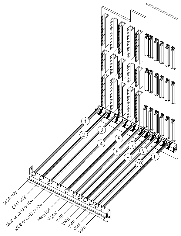
Locate the IO4 boards that are currently installed. As illustrated in Figure 2-1, slot 5 always has an IO4 board and slots 4 and 3 may contain IO4 boards. (A CHALLENGE L may have one to three IO4 boards installed.) Two mezzanine slots are located on each IO4 board. The short FCI mezzanine board included in the IRIS HIPPI package may be installed on any of the available mezzanine slots.
| Note: When installing an additional IRIS HIPPI network connection, be aware that the ordering of the FMezz boards determines the assignment of IP network interfaces to the IRIS HIPPI boards. During startup, the first FMezz board that is found with a HIPPI board attached is assigned network interface hip0; the second is assigned hip1, and so on. See Chapter 2 in the IRIS HIPPI Administrator's Guide for more details. |
In selecting a mezzanine slot, the following guidelines are suggested:
If the system has only one IO4 board, this is the location for the mezzanine board. The mezzanine board may be installed in either the upper or lower position on the IO4 board, as illustrated in Figure 2-2.
If the system has more than one IO4 board, select any unoccupied mezzanine slot as close as possible to your selected VMEBus slot. For example, a slot on the IO4 board in slot 5 is preferable to a slot on the IO4 board in slot 4.
If there are no unoccupied mezzanine slots, you must install another IO4 board. Contact the sales representative to order one. The installation cannot be continued until a mezzanine slot is available.
Note: The maximum number of IO4 boards for a CHALLENGE Deskside system is three. If three IO4 boards are already installed, and if all the mezzanine slots are occupied, IRIS HIPPI cannot be installed onto this system.
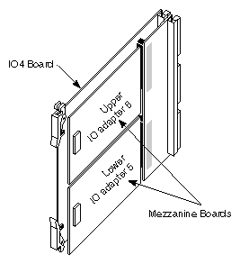
Follow the steps below to install the FCI mezzanine card.
Remove the IO4 board that you have selected from the CHALLENGE chassis.
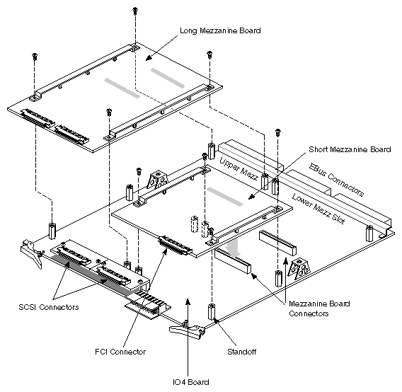
Lay the board on a flat antistatic surface so that the component side faces up and the SCSI connectors face toward you, as illustrated in Figure 2-3.
Locate the selected mezzanine slot (upper or lower) and remove the four screws from the standoffs, as illustrated in Figure 2-3. If the screws are missing, this is not a problem.
Attach the silver teflon-covered ribbon (FCI) cable to the FCI connector on the mezzanine board.
Caution: The teflon covering on the FCI cable is susceptible to puncturing. Be careful that its installation does not cause it to be pressed or positioned between sharp surfaces (for example, exposed pins).
The cable can be bent, folded, or creased one time without harm. But this type of handling should be done only to position the cable. Repeated handling of this type will break the wires.Position the mezzanine board onto the selected slot so that the connector on the bottom of the mezzanine board matches the mezzanine board receptacle on the IO4 board and the standoffs match the board's holes. Figure 2-3 illustrates the correct positioning for the upper and lower slots.
Replace the standoff screws. Use the screws removed previously or the shipped screws. The standoffs have a "float" feature, so the screws do not tighten completely.
Create an adapter identification for the mezzanine board. The identification has the format F-XX-5 for the lower slot and F-XX-6 for the upper slot, where XX is the slot number where the IO4 board resides. For example, a mezzanine board in the upper position on the main IO4 board located in slot 5 is labelled F-05-6.
From the sheet of labels, remove the two labels with the identification created in the previous step. Attach the larger label to the unattached end of the FCI cable. Attach the smaller-sized label to the outside of the HIPPI I/O panel plate.
Reinstall the IO4 board into the chassis, as illustrated in Figure 2-4. Push the board firmly into the backplane. If the board has a VCAM board, the VCAM board must also connect to the backplane.
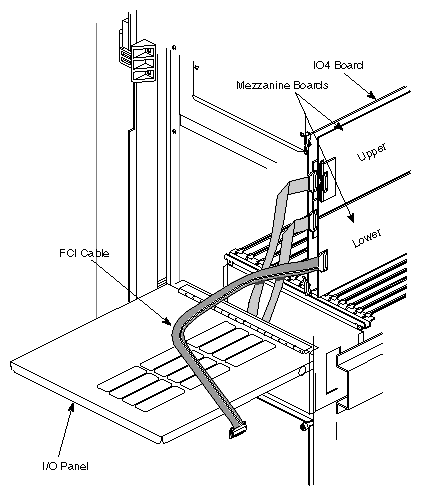
Follow the steps below to install the HIPPI board.
Hold the HIPPI board vertically so that the HIPPI and FCI connectors face you, the VMEBus connectors face away from you, and the side of the board with the most components faces to your right, as shown in Figure 2-5.
Position the edges of the board into the guides for the selected slot.
Slide the HIPPI board into its slot.
Push it firmly so that it seats into the backplane.
Attach the FCI cable, which was attached in a previous step to the mezzanine board, to the FCI connector on the HIPPI board.
Caution: The teflon covering on the FCI cable is susceptible to puncturing. Be careful that its installation does not cause it to be pressed or positioned between sharp surfaces (for example, exposed pins).
The cable can be bent, folded, or creased one time without harm. But this type of handling should be done only to position the cable. Repeated handling of this type will break the wires.
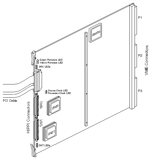
Follow the steps below to attach the internal HIPPI cables to the HIPPI board and the panel plate to the card cage's I/O panel.
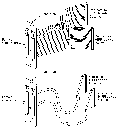
Locate the internal cable assembly that consists of the HIPPI I/O panel plate with two internal HIPPI cables attached. The cable assembly is one of the styles shown in Figure 2-6.
If the panel plate is not attached to the cables, screw the female connectors of the cables to the panel plate.
Remove one blank panel plate from the system's I/O panel and install the HIPPI panel plate.
Attach the two internal HIPPI cables to the HIPPI board and screw them into place.
The cable labelled HIPPI DST (on the panel plate) connects to the bottom connector, located nearest the floor.
The cable marked HIPPI SRC (on the panel plate) connects to the middle connector, located between the FCI connector and the HIPPI destination connector.
Close the I/O door(s) and the chassis doors.
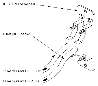
Attach the site's HIPPI cables to the system's IRIS HIPPI panel plate, as illustrated in Figure 2-7. Connect the port labelled HIPPI DST to the cable from the other system's (or switch's) source port. Attach the port labelled HIPPI SRC to the cable from the other system's (or switch's) destination port.
To finish the installation, do the following:
Flip the circuit breaker on the back of the chassis to ON, then turn the key switch on the front to ON.
When the console prompts you with the question Rebuild the operating system?, answer yes or y in order to build a new kernel.
Note: If this prompt does not appear, you probably have not installed the IRIS HIPPI software. Instead of proceeding with the steps below, follow the instructions in the IRIS HIPPI Release Notes to install and configure the software. Logon and reboot (this is the second time you are starting this system) to begin using the newly built operating system. The command lines below can be used to accomplish this step:
% su
Password: thepassword
# reboot
Logon and invoke /sbin/hinv to verify that the IRIS HIPPI hardware is listed:
% /sbin/hinv
. . .
IO4 HIPPI adapter: hippi#, slot # adap #, firmware version ########
Note: If the board is not listed, reinstall the product (both boards and all cables) making sure everything is firmly seated and tightly connected.
This section describes the steps for installing the IRIS HIPPI network product into a CHALLENGE XL Rackmount server. The CHALLENGE XL Rackmount platform supports up to four IRIS HIPPI boards.
Before starting the installation, prepare yourself and the equipment by following the instructions below.
Verify that the IRIS HIPPI package is complete. It should contain the items listed in Table 2-3.
Table 2-3. IRIS HIPPI Package Contents
Item | Quantity |
|---|---|
Short FCI mezzanine board | 1 |
HIPPI board | 1 |
Teflon-covered FCI (flat cable interface) cable assembly | 1 |
Internal HIPPI cable assembly | 1 |
Screws for attaching mezzanine board | 4 |
Labels with adapter IDs | 3 sheets |
CD-ROM with software (including online release notes) | 1 |
Documentation: |
|
If anything is missing, do not proceed with the installation. Contact the customer or the customer's salesperson.
Follow the instructions in this section to prepare the CHALLENGE XL Rackmount system for installation.
| Caution: This equipment is extremely sensitive and susceptible to damage by electrostatic discharge (ESD), a spark caused by the buildup of electrical static potential on clothing and other material. You must use proper ESD preventive measures as explained in the "Safety" section of the CHALLENGE/Onyx XL Rackmount Installation Instructions. |
Verify that the IRIX operating system is the correct version for this IRIS HIPPI release using the command below. Do not proceed until the correct version of IRIX is installed, as described in the IRIS HIPPI Release Notes.
% versions eoe1
I  eoe1  date  Execution Only Environment 1, version
Verify that the file system is backed up.
Optional, but recommended, step.
Install the IRIS HIPPI software, then do the required configuration steps. Step-by-step instructions are provided in the IRIS HIPPI Release Notes and the IRIS HIPPI Administrator's Guide. When the software is installed and configured, continue with the next step in these instructions.Note: You cannot verify successful installation of the board until the software is installed. If you choose not to install the software now, you will need to do so after the board has been installed. Shut down the system by turning the key on the System Controller panel (located at the front) to OFF. Wait a minute for the system to shut down, then switch the power switch on the lower front corner of the chassis to OFF.
Warning: Failure to turn off the main power switch may result in electrical shock. Failure to wait for the system to shut down may cause irreparable damage to system components or data. Open the back door and pull down the I/O panel for card cage 2 to expose the IO4 boards and VMEBus slots. If card cage 3 is present, pull down that I/O panel to expose the additional VMEBus slots.
To install the IRIS HIPPI network hardware, you need to locate two available slots in the CHALLENGE chassis: one mezzanine slot and one VMEBus slot. Table 2-4 lists the slots from which you can select. It is recommended that the mezzanine and VMEBus slots be as close to each other as possible because the FCI cable will connect them. However, the FCI cable is long enough to accommodate any boards in a properly configured CHALLENGE Rackmount system.
Table 2-4. Slots for IRIS HIPPI Installation in CHALLENGE XL Rackmount System
Slots Required | Slots That Can Be Used |
|---|---|
Short mezzanine slot | Upper or lower mezzanine slot on an IO4 board in slot 15, 13, 11, 9, 7, or 5 |
VMEBus slot | Slot 17, 18, 19, 20, or 21 in card cage 2; |
| Note: Instead of installing the FMezz board shipped with the IRIS HIPPI product, you may select an FCI connection on an already installed FMezz board (long or short). If you take this option, some of the steps in the section on installing the FMezz board can be skipped; however, other steps are relevant and very important, so do not skip the section. |
The VMEBus slots of the CHALLENGE XL Rackmount backplane that can be used for IRIS HIPPI are listed in Table 2-4 and illustrated in Figure 2-8 and Figure 2-9. For the HIPPI board, select the first unoccupied slot. Slot 17 is the first VMEBus slot; slot 18 is the second; and so on. If the optional card cage 3 is installed, slot 2 is the first VMEBus slot on the system's second VMEBus, while slot 3 is the second on that bus, and so on.
The following restrictions and guidelines should be followed in making your choice:
If you select a slot that is not the first available slot on that VMEBus (that is, if you skip a slot within a VMEBus), follow the instructions in the CHALLENGE/Onyx XL Rackmount Installation Instructions for jumpering across skipped slots.
Do not select a VMEBus slot that is reserved for use by a VCAM board (that is, slot 16 in card cage 2 or slot 1 in card cage 3).
It is possible to install the HIPPI board into a slot that is not serviced by a VCAM board. The VMEBus power module for the slot must be installed, but the VMEBus signals and negative voltages (provided by the VCAM) are not required. For example, you may install the HIPPI board into slot 2 of card cage 3, even if the VCAM in slot 1 is not installed. You will not, however, be able to use subsequent slots of that VMEBus (for example, 3 and 4) for VMEBus operations until a VCAM is installed into the first slot of the bank.
The IRIS HIPPI board typically uses 75 watts of power, drawn from its VMEBus slot. The board requires 5 volts at 15 amps and 12 volts at 1.5 amps. Verify that the slot you have chosen has appropriate power modules installed, and that heat dissipation/ventilation for this card cage can handle this additional board.
Because the IRIS HIPPI board occupies and jumpers a VMEBus slot (just like a normal VMEBus board), regular VMEBus boards may be installed in the slots downstream from the HIPPI board.
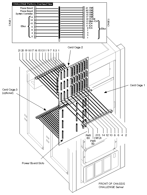
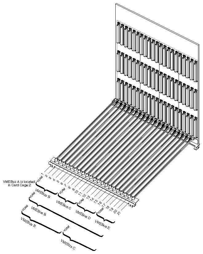
Locate the IO4 boards that are currently installed. As illustrated in Figure 2-8, slot 15 always has an IO4 board, and slots 13, 11, 9, 7, or 5 may contain IO4 boards. (A CHALLENGE XL Rackmount may have one to six IO4 boards installed.) Two mezzanine slots are located on each IO4 board. The short FCI mezzanine board included in the IRIS HIPPI package may be installed on any of the available mezzanine slots.
| Note: When installing an additional IRIS HIPPI network connection, be aware that the ordering of the FMezz boards determines the assignment of IP network interfaces to the IRIS HIPPI boards. During startup, the first FMezz board that is found with a HIPPI board attached is assigned network interface hip0; the second is assigned hip1, and so on. See Chapter 2 in the IRIS HIPPI Administrator's Guide for more details. |
In selecting a mezzanine slot, the following guidelines are suggested:
If the system has only one IO4 board, this is the location for the mezzanine board. The mezzanine board may be installed in either the upper or lower position on the IO4 board. Figure 2-10 illustrates an IO4 board with mezzanine boards in both slots.
If the system has more than one IO4 board, select an unoccupied mezzanine slot as close as possible to your selected VMEBus slot. For example, for a VMEBus slot in card cage 2, a slot on the IO4 board in slot 15 is preferable to a slot on the IO4 board in slot 13. However, for a VMEBus slot in card cage 3, a different IO4 board may be a better selection.
If there are no unoccupied mezzanine slots, you must install another IO4 board. Contact the customer or the customer's sales representative to order one. The installation cannot be continued until a mezzanine slot is available.
Note: The maximum number of IO4 boards for a CHALLENGE XL Rackmount system is eight. If eight IO4 boards are already installed, and if all the mezzanine slots are occupied, IRIS HIPPI cannot be installed onto this system.
Follow the steps below to install the FCI mezzanine card.
Remove the IO4 board that you have selected from the CHALLENGE chassis.
Lay the board on a flat antistatic surface so that the component side faces up and the SCSII connectors face toward you, as illustrated in Figure 2-11.
Locate the selected mezzanine slot (upper or lower) and remove the four screws from the standoffs, as illustrated in Figure 2-11. If the screws are missing, this is not a problem.
Attach the silver teflon-covered ribbon (FCI) cable to the FCI connector on the mezzanine board.
Caution: The teflon covering on the FCI cable is susceptible to puncturing. Be careful that its installation does not cause it to be pressed or positioned between sharp surfaces (for example, exposed pins).
The cable can be bent, folded, or creased one time without harm. But this type of handling should be done only to position the cable. Repeated handling of this type will break the wires.Position the mezzanine board onto the selected slot so that the connector on the bottom of the mezzanine board matches the mezzanine board receptacle on the IO4 board and the standoffs match the board's holes. Figure 2-11 illustrates the correct positioning for the upper and lower slots.
Replace the standoff screws. Use the screws removed previously or the shipped screws. The standoffs have a "float" feature, so the screws do not tighten completely.
Create an adapter identification for the mezzanine board. The identification has the format F-XX-5 for the lower slot and F-XX-6 for the upper slot, where XX is the slot number where the IO4 board resides. For example, a mezzanine board in the upper slot on the main IO4 board located in slot 15 is labelled F-15-6.
From the sheet of labels, remove the two labels with the identification created in the previous step. Attach the larger label to the unattached end of the FCI cable. Attach the smaller-sized label to the outside of the HIPPI I/O panel plate.
Reinstall the IO4 board into the chassis, as illustrated in Figure 2-12. Push the board firmly into the backplane. If the board has a VCAM board, the VCAM board must also connect to the backplane.
Follow the steps below to install the HIPPI board.
Hold the HIPPI board vertically so that the HIPPI and FCI connectors face you, the VMEBus connectors face away from you, and the side of the board with the most components faces to your right, as shown in Figure 2-13.
Position the edges of the board into the guides for the selected slot.
Slide the HIPPI board into its slot.
Push firmly so that it seats into the backplane.
Route the FCI cable, which was attached to the mezzanine board in a previous step, through the midplane to the selected VMEBus slot.
Caution: The teflon covering on the FCI cable is susceptible to puncturing. Be careful that its installation does not cause it to be pressed or positioned between sharp surfaces (for example, exposed pins).
The cable can be bent, folded, or creased one time without harm. But this type of handling should be done only to position the cable. Repeated handling of this type will break the wires.Attach the FCI cable to the connector on the HIPPI board.
Follow the steps below to attach the internal HIPPI cables to the HIPPI board and the panel plate to the card cage's I/O panel.
Locate the internal cable assembly that consists of the HIPPI I/O panel plate with two internal HIPPI cables attached. The cable assembly is one of the styles shown in Figure 2-14.
If the panel plate is not attached to the cables, screw the female connectors of the cables to the panel plate.
Remove one blank panel plate from the system's I/O panel and install the HIPPI panel plate.
Attach the two internal HIPPI cables to the HIPPI board and screw them into place.
The cable labelled HIPPI DST (on the panel plate) connects to the bottom connector, located nearest the floor.
The cable marked HIPPI SRC (on the panel plate) connects to the middle connector, located between the FCI connector and the HIPPI destination connector.
Close the I/O door(s) and the chassis doors.
Attach the site's HIPPI cables to the system's HIPPI panel plate connectors, as illustrated in Figure 2-15. Connect the I/O port labelled HIPPI DST to the cable from the other system's (perhaps switch's) source port. Attach the I/O port labelled HIPPI SRC to the cable from the other system's (perhaps switch's) destination port.
To finish the installation, do the following:
Flip the power switch on the front of the chassis to ON, then turn the key switch on the front to ON.
When the console prompts you with the question Rebuild the operating system?, answer yes or y in order to build a new kernel.
Note: If this prompt does not appear, you probably have not installed the IRIS HIPPI software. Instead of proceeding with the steps below, follow the instructions in the IRIS HIPPI Release Notes to install and configure the software. Logon and reboot (this is the second time you are starting this system) to begin using the newly built operating system. The command lines below can be used to accomplish this step:
% su
Password: thepassword
# reboot
Logon and invoke /sbin/hinv to verify that the IRIS HIPPI hardware is listed:
% /sbin/hinv
. . .
IO4 HIPPI adapter: hippi#, slot # adap #, firmware version ########
Note: If the board is not listed, reinstall the product (both boards and all cables) making sure everything is firmly seated and tightly connected.
This section describes the steps for installing the IRIS HIPPI network product into an Onyx Deskside server. The Onyx Deskside platform supports up to two IRIS HIPPI boards.
Before starting the installation, prepare yourself and the equipment by following the instructions below.
Verify that the IRIS HIPPI package is complete. It should contain the items listed in Table 2-5. If anything is missing, do not proceed with the installation. Contact the customer or the customer's salesperson.
Table 2-5. IRIS HIPPI Package Contents
Item | Quantity |
|---|---|
Short FCI mezzanine board | 1 |
HIPPI board | 1 |
Teflon-covered FCI (flat cable interface) cable assembly | 1 |
Internal HIPPI cable assembly | 1 |
Screws for attaching mezzanine board | 4 |
Labels with adapter IDs | 3 sheets |
CD-ROM with software (including online release notes) | 1 |
Documentation: |
|
Follow the instructions in this section to prepare the Onyx Deskside system for installation.
| Caution: This equipment is extremely sensitive and susceptible to damage by electrostatic discharge (ESD), a spark caused by the buildup of electrical static potential on clothing and other material. You must use proper ESD preventive measures as explained in the "Safety" section of the CHALLENGE/Onyx Deskside Installation Instructions. |
Verify that the IRIX operating system is the correct version for this IRIS HIPPI release, using the command below. Do not proceed until the correct version of IRIX is installed, as described in the IRIS HIPPI Release Notes.
% versions eoe1
I  eoe1  date  Execution Only Environment 1, version
Verify that the file system is backed up.
Optional, but recommended, step.
Install the IRIS HIPPI software, then do the required configuration steps. Step-by-step instructions are provided in the IRIS HIPPI Release Notes and the IRIS HIPPI Administrator's Guide. When the software is installed and configured, continue with the next step in these instructions.Note: You cannot verify successful installation of the board until the software is installed. If you choose not to install the software now, you will need to do so after the board has been installed. Shut down the system by turning the key on the System Controller panel (located at the front) to OFF. Wait a minute for the system to shut down, then switch the circuit breaker on the back to OFF.
Warning: Failure to turn off the circuit breaker may result in electrical shock. Failure to wait for the system to shut down may cause irreparable damage to system components or data. Open the front door and pull down the I/O panel in the front of the chassis to expose the VMEBus slots and IO4 board.
To install the IRIS HIPPI network hardware, you need to locate two available slots in the Onyx chassis: one mezzanine slot and one VMEBus slot. Table 2-6 lists the slots from which you can select. It is recommended that the mezzanine and VMEBus slots be as close to each other as possible because the FCI cable will connect them. However, the FCI cable is long enough to accommodate any boards in a properly configured Onyx Deskside system.
Table 2-6. Slots for IRIS HIPPI Installation in Onyx Deskside System
Slots Required | Slots That Can Be Used |
|---|---|
Short mezzanine slot | Upper or lower mezzanine slot on IO4 board in slot 3 |
VMEBus slot | Slot 5, 6, or 7 |
| Note: Instead of installing the FMezz board shipped with the IRIS HIPPI product, you may select an FCI connection on an already installed FMezz board (long or short). If you take this option, some of the steps in the section on installing the FMezz board can be skipped; however, other steps are relevant and very important, so do not skip the section. |
The VMEBus slots of the Onyx Deskside backplane that can be used for IRIS HIPPI are listed in Table 2-6 and illustrated in Figure 2-16. Select the first unoccupied slot for the HIPPI board. Slot 5 is the first VMEBus slot; slot 6 is the second; and so on.
| Note: If you select a slot that is not the first available slot (that is, if you skip a VMEBus slot), follow the instructions in the CHALLENGE/Onyx Deskside Installation Instructions for jumpering across skipped slots. |
The IRIS HIPPI board typically uses 75 watts of power, drawn from its VMEBus slot. The board requires 5 volts at 15 amps and 12 volts at 1.5 amps. Verify that the slot you have chosen has appropriate power modules installed, and that heat dissipation/ventilation for this card cage can handle this additional board.
Because the IRIS HIPPI board occupies and jumpers a VMEBus slot (just like a normal VMEBus board), regular VMEBus boards may be installed in the slots downstream from the HIPPI board.
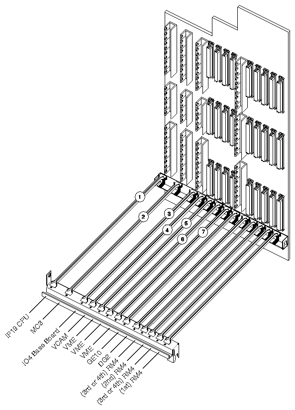
Two short mezzanine slots (upper and lower) are available on the system's IO4 board, as illustrated in Figure 2-17. The short FCI mezzanine board included in the IRIS HIPPI package may be installed on either of these slots. Figure 2-16 shows the IO4 board's location in the Onyx Deskside chassis.
| Note: If there are no unoccupied mezzanine slots on this IO4 board, IRIS HIPPI cannot be installed onto this system. The maximum number of IO4 boards for an Onyx Deskside system is one. |
Follow the steps below to install the FCI mezzanine card.
Remove the IO4 board from the Onyx chassis.
Lay the board on a flat antistatic surface so that the component side faces up and the SCSI connectors face toward you, as illustrated in Figure 2-18.
Locate the selected mezzanine slot (upper or lower) and remove the four screws from the standoffs, as illustrated in Figure 2-18. If the screws are missing, this is not a problem.
Attach the silver teflon-covered ribbon (FCI) cable to the FCI connector on the mezzanine board.
Caution: The teflon covering on the FCI cable is susceptible to puncturing. Be careful that its installation does not cause it to be pressed or positioned between sharp surfaces (for example, exposed pins).
The cable can be bent, folded, or creased one time without harm. But this type of handling should be done only to position the cable. Repeated handling of this type will break the wires.Position the mezzanine board onto the selected slot so that the connector on the bottom of the mezzanine board matches the mezzanine board receptacle on the IO4 board and the standoffs match the board's holes. Figure 2-19 illustrates the correct positioning for the upper and lower slots.
Replace the standoff screws. Use the screws removed previously or the shipped screws. The standoffs have a "float" feature, so the screws do not tighten completely.
Create an adapter identification for the mezzanine board. The identification is one of the following formats: F-03-5 for the lower slot or F-03-6 for the upper slot
From the sheet of labels, remove the two labels with the identification created in the previous step. Attach the larger label to the unattached end of the FCI cable. Attach the smaller-sized label to the outside of the HIPPI I/O panel plate.
Reinstall the IO4 board into the chassis, as illustrated in Figure 2-19. Push the board firmly into the backplane. If the board has a VCAM board, the VCAM board must also connect to the backplane.
Follow the steps below to install the HIPPI board.
Hold the HIPPI board vertically so that the HIPPI and FCI connectors face you, the VMEBus connectors face away from you, and the side of the board with the most components faces to your right, as shown in Figure 2-20.
Position the edges of the board into the guides for the selected slot.
Slide the HIPPI board into its slot.
Push firmly so that it seats into the backplane.
Attach the FCI cable, which was attached in a previous step to the mezzanine board, to the FCI connector on the HIPPI board.
Follow the steps below to attach the internal HIPPI cables to the HIPPI board and the panel plate to the card cage's I/O panel.
Locate the internal cable assembly that consists of the HIPPI I/O panel plate with two internal HIPPI cables attached. The cable assembly is one of the styles shown in Figure 2-21.
If the panel plate is not attached to the cables, screw the female connectors of the cables to the panel plate.
Remove one blank panel plate from the system's I/O panel and install the HIPPI panel plate.
Attach the two internal HIPPI cables to the HIPPI board and screw them into place.
The cable labelled HIPPI DST (on the panel plate) connects to the bottom connector, located nearest the floor.
The cable marked HIPPI SRC (on the panel plate) connects to the middle connector, located between the FCI connector and the HIPPI destination connector.
Close the I/O door(s) and the chassis doors.
Attach the site's HIPPI cables to the system's HIPPI panel plate connectors, as illustrated in Figure 2-22. Connect the port labelled HIPPI DST to the cable from the other system's (or switch's) source port. Attach the port labelled HIPPI SRC to the cable from the other system's (or switch's) destination port.
To finish the installation, do the following:
Flip the circuit breaker on the back of the chassis to ON, then turn the key switch on the front to ON.
When the console prompts you with the question Rebuild the operating system?, answer yes or y in order to build a new kernel.
Note: If this prompt does not appear, you probably have not installed the IRIS HIPPI software. Instead of proceeding with the steps below, follow the instructions in the IRIS HIPPI Release Notes to install and configure the software. Logon and reboot (this is the second time you are starting this system) to begin using the newly built operating system. The command lines below can be used to accomplish this step:
% su
Password: thepassword
# reboot
Logon and invoke /sbin/hinv to verify that the IRIS HIPPI hardware is listed:
% /sbin/hinv
. . .
IO4 HIPPI adapter: hippi#, slot # adap #, firmware version ########
Note: If the board is not listed, reinstall the product (both boards and all cables) making sure everything is firmly seated and tightly connected.
This section describes the steps for installing the IRIS HIPPI network product into an Onyx Rackmount server. The Onyx Rackmount platform supports up to four IRIS HIPPI boards.
Before starting the installation, prepare yourself and the equipment by following the instructions below.
Verify that the IRIS HIPPI package is complete. It should contain the items listed in Table 2-7. If anything is missing, do not proceed with the installation. Contact the customer or the customer's salesperson.
Table 2-7. IRIS HIPPI Package Contents
Item | Quantity |
|---|---|
Short FCI mezzanine board | 1 |
HIPPI board | 1 |
Teflon-covered FCI (flat cable interface) cable assembly | 1 |
Internal HIPPI cable assembly | 1 |
Screws for attaching mezzanine board | 4 |
Labels with adapter IDs | 3 sheets |
CD-ROM with software (including online release notes) | 1 |
Documentation: |
|
Follow the instructions in this section to prepare the Onyx Rackmount system for installation.
| Caution: This equipment is extremely sensitive and susceptible to damage by electrostatic discharge (ESD), a spark caused by the buildup of electrical static potential on clothing and other material. You must use proper ESD preventive measures as explained in the "Safety" section of the CHALLENGE/Onyx XL Rackmount Installation Instructions. |
Verify that the IRIX operating system is the correct version for this IRIS HIPPI release using the command below. Do not proceed until the correct version of IRIX is installed, as described in the IRIS HIPPI Release Notes.
% versions eoe1
I  eoe1  date  Execution Only Environment 1, version
Verify that the file system is backed up.
Optional, but recommended, step.
Install the IRIS HIPPI software, then do the required configuration steps. Step-by-step instructions are provided in the IRIS HIPPI Release Notes and the IRIS HIPPI Administrator's Guide. When the software is installed and configured, continue with the next step in these instructions.Note: You cannot verify successful installation of the board until the software is installed. If you choose not to install the software now, you will need to do so after the board has been installed. Shut down the system by turning the key on the System Controller panel (located at the front) to OFF. Wait a minute for the system to shut down, then switch the power switch on the lower front corner of the chassis to OFF.
Warning: Failure to turn off the main power switch may result in electrical shock. Failure to wait for the system to shut down may cause irreparable damage to system components or data. Open the back door and pull down the I/O panel for card cage 2 to expose the IO4 boards and VMEBus slots. If card cage 3 is present, pull down that I/O panel to expose the additional VMEBus slots.
To install the IRIS HIPPI network hardware, you need to locate two available slots in the Onyx chassis: one mezzanine slot and one VMEBus slot. Table 2-8 lists the slots from which you can select. It is recommended that the mezzanine and VMEBus slots be as close to each other as possible because the FCI cable will connect them. However, the FCI cable is long enough to accommodate any boards in a properly configured Onyx Rackmount system.
Table 2-8. Slots for IRIS HIPPI Installation in Onyx Rackmount System
Slots Required | Slots That Can Be Used |
|---|---|
Short mezzanine slot | Upper or lower mezzanine slot on an IO4 board in slot 11, 9, 7, or 5 |
VMEBus slot | Slot 13, 14, or 15 in card cage 2; |
| Note: Instead of installing the FMezz board shipped with the IRIS HIPPI product, you may select an FCI connection on an already installed FMezz board (long or short). If you take this option, some of the steps in the section on installing the FMezz board can be skipped; however, other steps are relevant and very important, so do not skip the section. |
The VMEBus slots of the Onyx Rackmount backplane that can be used for IRIS HIPPI are listed in Table 2-8 and illustrated in Figure 2-23 and Figure 2-24. For the HIPPI board, select the first unoccupied slot. Slot 13 is the first VMEBus slot; slot 14 is the second; and so on. If the optional card cage 3 is installed, slot 2 is the first VMEBus slot on the system's second VMEBus, while slot 3 is the second on that bus and so on.
The following restrictions and guidelines should be followed in making your choice:
If you select a slot that is not the first available slot on that VMEBus (that is, if you skip a slot within a VMEBus), follow the instructions in the CHALLENGE/Onyx XL Rackmount Installation Instructions for jumpering across skipped slots.
Do not select a VMEBus slot that is reserved for use by a VCAM board (that is, slot 12 in card cage 2 or slots 1 or 11 in card cage 3).
It is possible to install the HIPPI board into a slot that is not serviced by a VCAM board. The VMEBus power module for the slot must be installed, but the VMEBus signals and negative voltages (provided by the VCAM) are not required. For example, you may install the HIPPI board into slot 2 of card cage 3, even if the VCAM in slot 1 is not installed. You will not, however, be able to use subsequent slots of that VMEBus (for example, 3 and 4) for VMEBus operations until a VCAM is installed into the first slot of the bank.
The IRIS HIPPI board typically uses 75 watts of power, drawn from its VMEBus slot. The board requires 5 volts at 15 amps and 12 volts at 1.5 amps. Verify that the slot you have chosen has appropriate power modules installed, and that heat dissipation/ventilation for this card cage can handle this additional board.
Because the IRIS HIPPI board occupies and jumpers a VMEBus slot (just like a normal VMEBus board), regular VMEBus boards may be installed in the slots downstream from the HIPPI board.
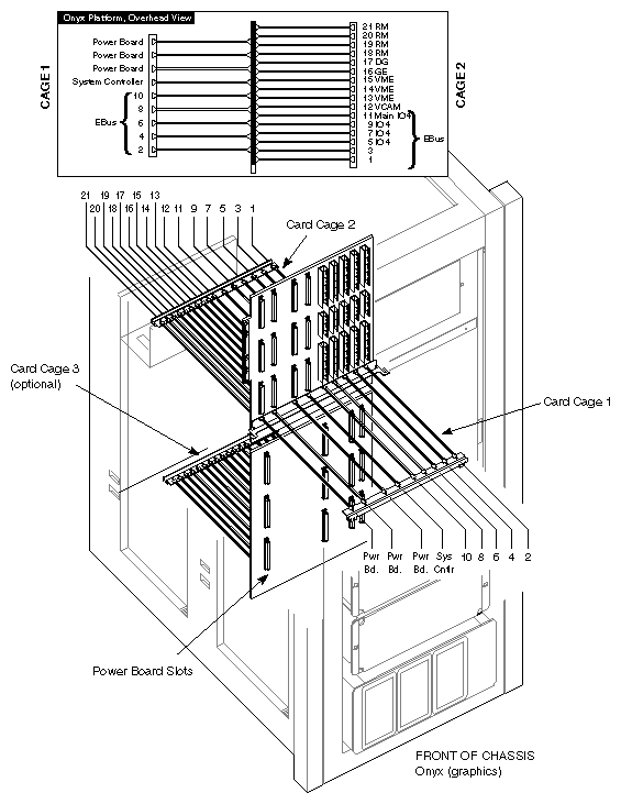
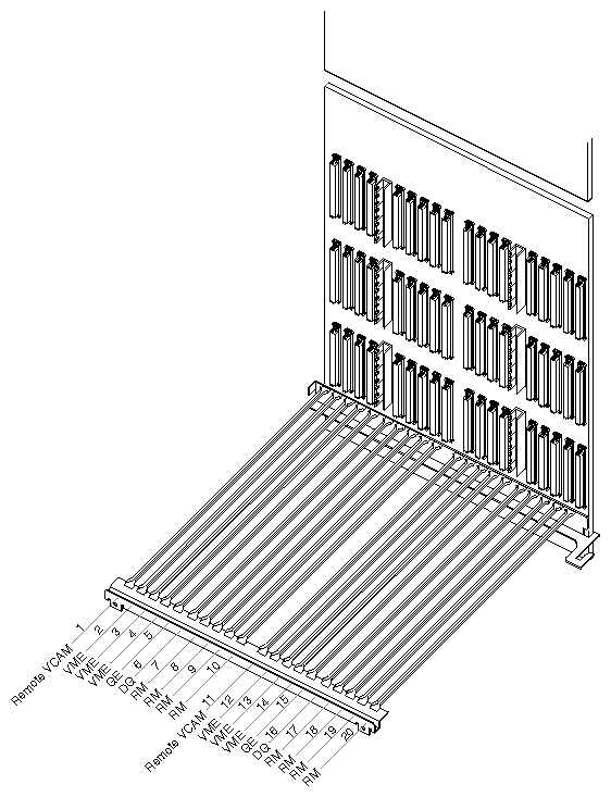
Locate the IO4 boards currently installed. As illustrated in Figure 2-23, slot 11 always has an IO4 board, and slots 9, 7, or 5 may contain IO4 boards. (An Onyx Rackmount may have one to four IO4 boards installed.) Two mezzanine slots are located on each IO4 board. The short FCI mezzanine board included in the IRIS HIPPI package may be installed on any of the available mezzanine slots.
| Note: When installing an additional IRIS HIPPI network connection, be aware that the ordering of the FMezz boards determines the assignment of IP network interfaces to the IRIS HIPPI boards. During startup, the first FMezz board that is found with a HIPPI board attached is assigned network interface hip0; the second is assigned hip1, and so on. See Chapter 2 in the IRIS HIPPI Administrator's Guide for more details. |
In selecting a mezzanine slot, the following guidelines are suggested:
If the system has only one IO4 board, this is the location for the mezzanine board. The mezzanine board may be installed in either the upper or lower position on the IO4 board. Figure 2-25 illustrates an IO4 board with mezzanine boards in both slots.
If the system has more than one IO4 board, select an unoccupied mezzanine slot that is as close as possible to your selected VMEBus slot. For example, for a VMEBus slot in card cage 2, a slot on the IO4 board in slot 11 is preferable to a slot on the IO4 board in slot 19. However, for a VMEBus slot in card cage 3, a different IO4 board may be a better selection.
If there are no unoccupied mezzanine slots, you must install another IO4 board. Contact the sales representative to order one. The installation cannot be continued until a mezzanine slot is available.
Note: The maximum number of IO4 boards for an Onyx Rackmount system is six. If six IO4 boards are already installed, and if all the mezzanine slots are occupied, IRIS HIPPI cannot be installed onto this system.
Follow the steps below to install the FCI mezzanine card.
Remove the IO4 board that you have selected from the Onyx chassis.
Lay the board on a flat antistatic surface so that the component side faces up and the SCSI connectors face toward you, as illustrated in Figure 2-26.
Locate the selected mezzanine slot (upper or lower) and remove the four screws from the standoffs, as illustrated in Figure 2-26. If the screws are missing, this is not a problem.
Attach the silver teflon-covered ribbon (FCI) cable to the FCI connector on the mezzanine board.
Caution: The teflon covering on the FCI cable is susceptible to puncturing. Be careful that its installation does not cause it to be pressed or positioned between sharp surfaces (for example, exposed pins).
The cable can be bent, folded, or creased one time without harm. But this type of handling should be done only to position the cable. Repeated handling of this type will break the wires.Position the mezzanine board onto the selected slot so that the connector on the bottom of the mezzanine board matches the mezzanine board receptacle on the IO4 board and the standoffs match the board's holes. Figure 2-26 illustrates the correct positioning for the upper and lower slots.
Replace the standoff screws. Use the screws removed previously or the shipped screws. The standoffs have a "float" feature, so the screws do not tighten completely.
Create an adapter identification for the mezzanine board. The identification has the format F-XX-5 for the lower slot and F-XX-6 for the upper slot, where XX is the slot number where the IO4 board resides. For example, a mezzanine board in the upper slot on the main IO4 board located in slot 11 is labelled F-11-6.
From the sheet of labels, remove the two labels with the identification created in the previous step. Attach the larger label to the unattached end of the FCI cable. Attach the smaller-sized label to the outside of the HIPPI I/O panel plate.
Reinstall the IO4 board into the chassis, as illustrated in Figure 2-27. Push the board firmly into the backplane. If the board has a VCAM board, the VCAM board must also connect to the backplane.
Follow the steps below to install the HIPPI board.
Hold the HIPPI board vertically so that the HIPPI and FCI connectors face you, the VMEBus connectors face away from you, and the side of the board with the most components faces to your right, as shown in Figure 2-28.
Position the edges of the board into the guides for the selected slot.
Slide the HIPPI board into its slot.
Push firmly so that it seats into the backplane.
Route the FCI cable, which was attached to the mezzanine board in a previous step, through the midplane to the selected VMEBus slot.
Caution: The teflon covering on the FCI cable is susceptible to puncturing. Be careful that its installation does not cause it to be pressed or positioned between sharp surfaces (for example, exposed pins).
The cable can be bent, folded, or creased one time without harm. But this type of handling should be done only to position the cable. Repeated handling of this type will break the wires.Attach the FCI cable to the connector on the HIPPI board.
Follow the steps below to attach the internal HIPPI cables to the HIPPI board and the panel plate to the card cage's I/O panel.
Locate the internal cable assembly that consists of the HIPPI I/O panel plate with two internal HIPPI cables attached. The cable assembly is one of the styles shown in Figure 2-29.
Remove one blank panel plate from the system's I/O panel and install the HIPPI panel plate.
Attach the two internal HIPPI cables to the HIPPI board and screw them into place.
The cable labelled HIPPI DST (on the panel plate) connects to the bottom connector, located nearest the floor.
The cable marked HIPPI SRC (on the panel plate) connects to the middle connector, located between the FCI connector and the HIPPI destination connector.
Close the I/O door(s) and the chassis doors.
Attach the site's HIPPI cables to the system's HIPPI panel plate connectors, as illustrated in Figure 2-30. Connect the I/O port labelled HIPPI DST to the cable from the other system's (perhaps switch's) source port. Attach the I/O port labelled HIPPI SRC to the cable from the other system's (perhaps switch's) destination port.
To finish the installation, do the following:
Flip the power switch on the front of the chassis to ON, then turn the key switch on the front to ON.
When the console prompts you with the question Rebuild the operating system?, answer yes or y in order to build a new kernel.
Note: If this prompt does not appear, you probably have not installed the IRIS HIPPI software. Instead of proceeding with the steps below, follow the instructions in the IRIS HIPPI Release Notes to install and configure the software. Logon and reboot (this is the second time you are starting this system) to begin using the newly built operating system. The command lines below can be used to accomplish this step:
% su
Password: thepassword
# reboot
Logon and invoke /sbin/hinv to verify that the IRIS HIPPI hardware is listed:
% /sbin/hinv
. . .
IO4 HIPPI adapter: hippi#, slot # adap #, firmware version ########
Note: If the board is not listed, reinstall the product (both boards and all cables) making sure everything is firmly seated and tightly connected.