This chapter is an introduction to the High-Performance Parallel Interface (HIPPI) protocol and the IRIS HIPPI hardware. The chapter provides a brief introduction to HIPPI, a description of the HIPPI protocol, some common configurations of HIPPI equipment, how to obtain official HIPPI documentation, and a theory of operations section for the IRIS HIPPI hardware.
This section provides a brief introduction to HIPPI.
HIPPI uses source to refer to the transmitting host, endpoint, network interface, or program.
It uses destination to refer to the receiving host, endpoint, network interface, or program.
HIPPI is an extremely fast, simplex point-to-point protocol. HIPPI provides for transmission at 800 or 1600 megabits per second[1] . Before data can be sent from one HIPPI network interface (endpoint) to another there must be both a physical link and an open connection between them. The physical link is made up of one or more 25-meter sections of copper cable. Each section connects two HIPPI nodes. The nodes can be endpoints or intermediate HIPPI switches. The open connection is an agreement for data transfer from one endpoint to another, and is arranged with an exchange of signals. Once a connection is open the entire physical link is dedicated to one-way communication from the source to the destination.
Figure 1-1 illustrates a configuration of HIPPI equipment with six physical links. This configuration supports nine different endpoint-to-endpoint communication paths (listed below) of which three can be simultaneously active:
A-source transmitting to C-destination, B-destination, or A-destination (itself)
B-source transmitting to C-destination, B-destination (itself), or A-destination
C-source transmitting to C-destination (itself), B-destination, or A-destination
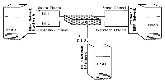
An open connection consists of an exchange of signals between a source and a destination. During this exchange, the destination agrees to accept data exclusively from the source. Each endpoint-to-endpoint link supports one connection (that is, HIPPI is point to point). It is common for an interface's source and destination channels to have open connections with different hosts (for example, A-source connected to B-destination while A-destination is connected to C-source). To move data in both directions between two hosts, two endpoint-to-endpoint links and two open connections are needed between the two hosts.
Unlike Ethernet, 802.5 Token Ring, or FDDI, HIPPI does not use a shared medium. Once a connection is established, the cable between the two HIPPI interfaces contains only packets transmitted by the source (that is, HIPPI connections are simplex). HIPPI packets may be seen by intermediate switches but not by other host interfaces. When one packet has been sent, the connection may be closed or kept open so that additional packets can be sent; however, each endpoint may not participate in another connection until the current one has been closed.
HIPPI communication is controlled by three basic functions: connection control, packet and flow control, and routing control (pertinent only when one or more switches are involved). Each of these is discussed separately in the subsections that follow.
One of the first things any HIPPI endpoint does upon startup is to assert its two outgoing INTERCONNECT signals and to look for assertion of its two incoming INTERCONNECT signals. Each channel (the source and the destination) has both incoming and outgoing INTERCONNECT signals. When both signals on a channel are asserted, the physical link between the local system and the system at the other end is ready for use. When the other system is a switch, the exchange of INTERCONNECT signals occurs between the endpoint and the switch, not between endpoints.
Before a source (transmitting) HIPPI network interface can send a packet, it must open a connection to one destination HIPPI endpoint. The source interface is always the initiator for opening the connection. To open a connection, the sender issues a connection request by asserting the REQUEST signal on the link. Each connection request includes an I-field (described in Section 1.2.1). The I-field mainly contains routing information, used by any switches encountered along the path to the destination.
The destination accepts a connection by asserting its CONNECT signal in response to the request. If the destination endpoint is unwilling to accept the connection or if there is a problem with the connection request (for example, bad parity on the I-field or incompatible word size), the connection request is denied (that is, acknowledged, then rejected). The transmitter must wait and try again later or forgo the communication. If the destination is unreachable (for example, a broken physical link, a powered-down or dysfunctional network interface), there is no response and the source program times out.
When a switch exists between the source and destination, the source receives its connection rejections from the switch, not directly from the destination. The rejection can be caused by any of the following conditions, and it is not possible to distinguish among them (except as explained below):
the destination is malfunctioning
the destination refuses to accept the requested connection
the connection request has an error
a section of the physical link to the destination is busy (currently engaged in another connection)
A feature is available that allows the source to be informed of rejections due to error conditions (items 1-3 above) but not to be informed (bothered) when the rejection is due to a busy link (item 4). This feature is called camp-on. By setting the camp-on bit in the I-field, the source can program the switches to hold onto the connection request until the busy link to the destination becomes available.
When the Camp-on bit is set, the first switch enqueues the connection request if it finds any link along the path to the destination busy. The switch periodically checks to see if the link has become available. When the link becomes available, it sends the connection request. A switch will continue to wait until it sends the REQUEST to the ultimate destination endpoint or until the source aborts the connection request. If a number of sources are all trying to send data through the same link, the camp-on feature ensures fair (first come, first served) access to the link.
Once opened, a HIPPI connection may be kept open for as long as the two endpoints maintain it. Either endpoint may terminate the connection at any point in time; however, the source network interface is usually the initiator.
Once a connection is open, one or multiple packets may be sent. The destination indicates it is ready to receive data by sending a READY signal to the source endpoint. Each READY allows the source to transmit one HIPPI burst (as explained below). All HIPPI source endpoints are required to be capable of enqueuing a minimum of 63 READYs. There is no minimum requirement for a destination's ability to generate READYs[2] . By sending ahead and queuing READYs, the two endpoints can optimize the throughput on their connection.
The source delineates its packets with the PACKET signal: at the beginning it asserts the PACKET signal, and at the end it deasserts the signal. A HIPPI packet consists of one or more bursts, as illustrated in Figure 1-2. Each burst contains 256 words, except in the case where the burst is short (as described below). The size of each word depends on the source's data bus (32 or 64 bits, as indicated by a bit in the I-field)[3] . At the end of each burst, the source generates a checksum (LLRC) so that the destination can detect any errors in the received data; in addition, each word has four bits of parity for error checking.
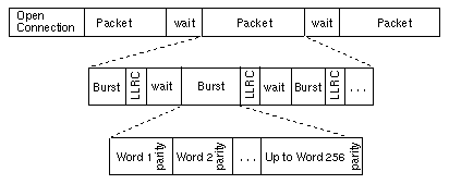
The HIPPI protocol requires very small waiting periods between packets and between bursts. These required periods are counted in nanoseconds and are essentially imperceptible to the user; however, in normal operation there may be noticeable pauses between bursts (for example, when the source is waiting to receive a READY).
As long as the source has READYs, it can transmit data as fast as it is capable of transmitting (but no faster than the protocol allows: 25 million words per second). When the sender has sent all the data for one packet, it indicates the end of the packet, using the PACKET signal. Indicating the end of the packet is necessary because HIPPI allows packet size to be undefined (indeterminate) at the start of the packet. A sender could essentially send an infinite–sized packet by keeping the PACKET signal asserted at all times.
A packet's first burst often contains some kind of header (for example, a HIPPI-FP header as described in Section 1.2). The first burst can contain header only or header and user data. In other words, the first words of user data can be in the first burst or the second. If the source program is generating HIPPI-FP packets, it can indicate the location of the packet's first word of user data by setting the B bit in the HIPPI-FP header.
Either the first or the last burst of a packet (but not both) can be less than 256 words. This burst is referred to as a short burst. Usually, the last burst is the short one. When the first burst is the short one, it contains only the header, and optionally, control information. The first word of user data is located in the second burst, and the final burst may be padded to meet the 256-word length requirement. When the last burst is the short one, the packet's final burst never needs to be padded and the first word of user data may be included in the first burst.
Once the end of the packet has been indicated, the source has the option of keeping the connection open to transmit additional packets or of closing the connection.
The I-field contains HIPPI routing information in its 24-bit Routing Control field. This information is interpreted only by intermediate systems (switches); the Routing Control information is not interpreted when a connection is directly between two end systems.
The addresses in a Routing Control field can be in "logical addressing" or "source addressing" format. The format is indicated by the Path Selection bits of the I-field. The two formats cannot be used simultaneously in one I-field; however, both formats can be used simultaneously in one HIPPI local area network (LAN).
 | Note: The word source in "source addressing format" does not mean that the address is the source's address; it refers to the fact that the address supplied by the sending endpoint defines the complete path (route). |
With logical addressing, the Routing Control field contains two 12-bit addresses: a destination (receiver's) address and a source (sender's) address, as illustrated in Figure 1-3. The order in which the addresses are placed within the field is defined by the Direction bit, as illustrated in Figure 1-3. Some switch implementations do not require inclusion of the sender's address, in which case these bits are set to zero.
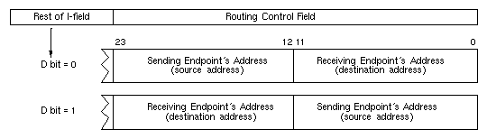
When a HIPPI LAN uses logical addressing, each HIPPI network interface (endpoint) within the LAN is assigned an address that is unique within that LAN. One address can be used for both the source and destination channels of a network interface, if desired. Assignment of these addresses is a local matter; the addresses do not need to be unique outside the particular HIPPI network. Logical addresses for LAN source and destination network interfaces have the format xxxx x0xx xxxx binary. Addresses with the format 1111 11xx xxxx binary are reserved by the HIPPI-SC standard for special assignments.
Each switch maintains a "map" of its LAN and uses a routing table to select the path along which to open a connection for each request. For example, Figure 1-4 illustrates a scenario where two paths are available between network interface A and B. When interface A requests a connection to interface B, switch 1 can select either of these paths.
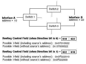
| Note: All the sample I-fields (in hexadecimal notation) in Figure 1-4 include a Camp-on bit set to one. |
The 12 bits make it possible to create 4096 unique endpoint addresses. The HIPPI-SC standard reserves 64 of these addresses, leaving 4032 addresses available for local assignment to HIPPI end points (for example, network interfaces).
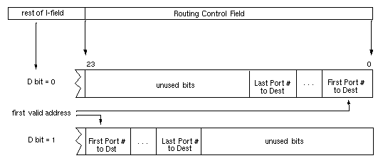
An address for source addressing can be from 1 to 24 bits long. The address is a "path" (explained in more detail below), and the Routing Control field contains one address. When the Path Selection bits in the I-field indicate that source addressing is being used, the Routing Control field contains a list of port identifiers, as illustrated in Figure 1-5. The I-field's Direction bit determines the order in which the port identifiers are placed within the field and the alignment of (placement for) the addresses, as illustrated in Figure 1-5.
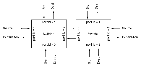
Each port identifier uniquely identifies one port within a switch. A port is a pair of physical links: both a source and a destination. For example, a 4x4 switch has 8 physical links to 4 systems, and for this it uses 4 port identifiers, as illustrated in Figure 1-6. Port identifiers are unique among all the ports on the same switch, but not among all the ports within the LAN. For example, a LAN with 5 switches might easily have 5 port identifiers of "1." Figure 1-6 is an example of the port identifiers for a LAN with 2 switches.
A Routing Control field in source address format is interpreted as a series of "stepping stones" in the following manner:
The first switch (the one attached to the source endpoint) reads the first port identifier, opens a connection at that outgoing port, and sends the I-field (that is, the connection request).
If the system at the end of that physical link is another switch, it reads the second port identifier, opens a connection at that outgoing port, and sends the I-field.
And so on, until the receiving system is the destination endpoint.
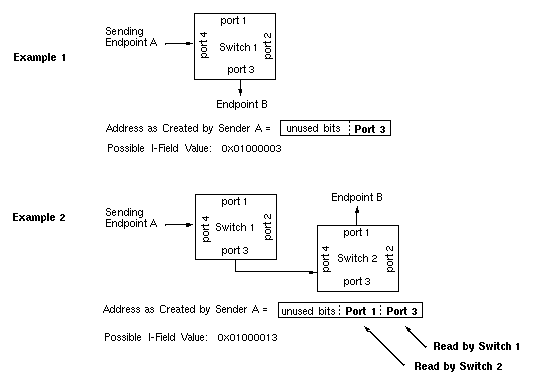
When the port identifiers are followed sequentially, they create the path between the two endpoints. Each path (address) consists of a list of all the outgoing ports through which the connection request must pass in order to reach the destination. For example, in the simplest configuration, where one switch exists between two network interfaces, the address consists of one port identifier: the one to which the receiving interface is connected, as illustrated in Example 1 in Figure 1-7. When two switches exist between the interfaces, the address consists of two port identifiers, as illustrated in Example 2 of Figure 1-7.
Each HIPPI host within the LAN maintains a table of paths (addresses in source addressing format) for reaching each of the other endpoints. With each of its connection requests, a source attaches one of these paths, thus indicating how to reach the destination. The path is completely defined by the sending endpoint.
The Direction bit in the I-field defines whether each port identifier should be read from the most significant or least significant end of the Routing Control field. For example, Figure 1-8 illustrates two addresses that network interface A might use to open a connection with B.
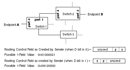
| Note: The sample I-Fields in Figure 1-7 and Figure 1-8 assume that the Camp-on bit is set and that the switches require four bits for each port identifier. |
Unlike logical addresses (which are not altered enroute to the destination), addresses in source addressing format are changed by each switch that handles the I-field. The sender creates a list of outgoing port numbers that define a path from the sender to the receiver. By the time the packet arrives at its destination, the address has been altered so that it defines the return path (that is, the path from the receiver back to the sender). This change is brought about by each switch removing its outgoing port identifier and adding an incoming port identifier (that is, the port through which the I-field just arrived), as illustrated in Figure 1-9.
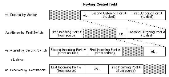
A destination program can copy received a Routing Control field into its own I-field and simply change the setting of the Direction bit to open a return connection, thus bypassing the table lookup procedure. Normally, the source that first creates the Routing Control field sets the D bit to zero and places the address bits in the least significant positions of the Routing Control field. The receiver changes the setting for the D bit and uses the received Routing Control field exactly as it is received. In this manner, the port identifier labeled Last Incoming Port # in Figure 1-9 becomes the First Outgoing Port # for the return connection.
Port identifiers can be one to six bits. The number of bits varies from switch to switch. The size of the port identifier is the number of bits needed to identify all the possible ports on a switch uniquely. For example, a 4x4 switch has four ports and requires at least two–bit port identifiers (binary port identifiers 00, 01, 10, and 11). If a switch is capable of being enlarged, it may use large–sized port identifiers (for example, five or six bits) to avoid a reconfiguration of all the LAN's routing tables when the switch is upgraded.
The I-field's 24-bit Routing Control field limits the number of port identifiers that can be contained in an address, as summarized in Table 1-1.
Table 1-1. Maximum Number of Port Identifiers in Routing Control Field
mber of Bits Used in Port Identifier | Maximum Number of Port Identifiers Possible in Routing Control Field |
|---|---|
1 | 24 |
2 | 12 |
3 | 8 |
4 | 6 |
5 | 4 |
6 | 4 |
This section describes the format for the HIPPI I-field and FP header.
The format for the 32-bit HIPPI I-field is shown in Figure 1-10, and its fields are explained in Table 1-2.

Table 1-2. Fields of the HIPPI I-field
Field | Bits | Description |
|---|---|---|
L | 31 | Local or Standard Format 0 = Bits 30:0 of I-field conform to the usage described in this table. 1 = Bits 30:0 are implemented in conformance to a private (locally defined) |
| 30:29 | Vendor Unique Bits Vendors of end-system HIPPI equipment may use these bits for any purpose. Switches do not alter or interpret these bits. |
W | 28 | Width 0 = The data bus of the transmitting (source) HIPPI is 32-bits wide for 800 1 = Source's data bus is 64-bits wide for 1600 Mbits/second transmission. |
D | 27 | Direction 0 = Least significant bits of Routing Control field contain the destination 1 = Most significant bits of Routing Control field contain the destination address |
PS | 26:25 | Path Selection 00 = Source routing. 01 = Logical routing. Switch must select first route from its list of routes. 10 = Reserved. 11 = Logical routing. Switch selects any (or best) route from its list of routes. |
C | 24 | Camp-on 0 = Switch rejects connection request immediately if port to destination is busy. 1 = Switch holds connection request if port to destination is busy and establishes connection when the port becomes free or when source aborts the request. |
Routing | 23:0 | Address This field contains addressing/routing information. The contents are in source routing or logical routing format, as indicated by the PS field. For source routing, the field contains a list of switch port identifiers that, when followed, lead to the destination. For logical addressing, the field contains two 12-bit addresses (receiver's and sender's) that are used by the intermediate switches to select a route from a table. |
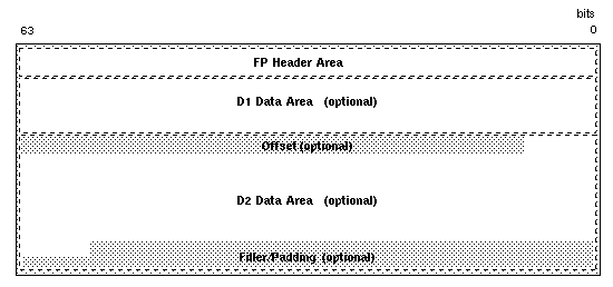
When a HIPPI endpoint is HIPPI-FP conformant, all the packets it transmits and/or receives (without error) are HIPPI-FP packets. The first burst of each of its transmitted packets contains an FP header, and it looks for an FP header in the first burst of each received packet. A HIPPI-FP packet consists of three segments, listed below and illustrated in Figure 1-11:
Framing Protocol Header
This area contains the 64-bit HIPPI-FP header, described in more detail in Table 1-3.D1_Data
This optional area may contain control information. The content and format are locally defined. For example, each upper–layer application (ULP-id) could use a different format for its D1 data. The D1 area can be 0 to 255 words in size.D2_Data
This area contains the user/application data. This area can be 0 to (4 gigabytes minus 1 byte) in size.
The 64-bit FP header describes the HIPPI packet using six fields, illustrated in Figure 1-12 and described in Table 1-3.
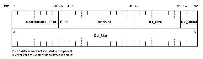
Table 1-3. Fields of the HIPPI-FP Header
Field | Bits | Description |
|---|---|---|
ULP-id | 63:56 | The 8-bit upper–layer protocol identification field identifies a system's upper–layer protocols. A transmitting application uses this number to specify the intended upper–layer recipient of the packet. A receiving HIPPI subsystem can use this number to demultiplex incoming packets among a number of upper–layer applications and to determine whether an intended recipient is known or not. |
P bit | 55 | The 1-bit present bit indicates whether or not the packet contains D1 data. |
B bit | 54 | The 1-bit burst boundary bit indicates which burst contains the first byte of D2 data. D2 data can be included in the first burst or can start with the first word of the second burst. |
D1 Size | 42:35 | The 8-bit D1 size field indicates the number of 64-bit words of D1 data included in this packet. |
D2 Offset | 34:32 | The 3-bit D2 offset field indicates the number of bytes between the last byte of D1 data and the first byte of D2 data. |
D2 Size | 31:0 | The 32-bit D2 size field indicates the number of bytes of D2 data included in this packet. Bytes of offset or fill are not included in this count. |
This section describes some of the common configurations of HIPPI equipment. Because HIPPI is a simplex point-to-point protocol, only one network interface at a time can transmit onto the transport medium (cable) between two endpoints. Two physical links (cables) are required for bidirectional communication. This aspect of HIPPI makes it quite different from protocols such as Ethernet, FDDI, or 802.5 Token Ring.
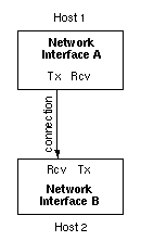
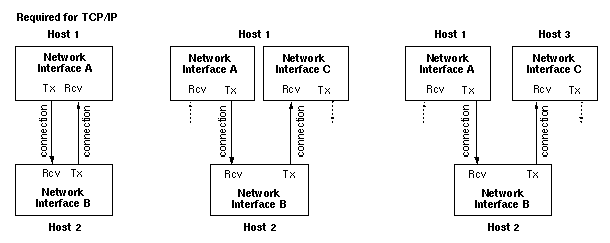
A basic (non–networked) HIPPI configuration consists of two endpoints, with one sending and the other receiving, as shown in Figure 1-13. To exchange data in both directions, two physical links and two connections are required between the two endpoints, as shown in Figure 1-14. Each endpoint's source channel must open a connection with the destination of the other endpoint.
The IRIS HIPPI network interface board has two channels (I/O ports). It treats each one as a separate entity, so each IRIS HIPPI network interface supports two autonomous, simultaneous connections: one sending data and one receiving data. The two channels can be communicating with two different endpoints (as shown by the examples on the right in Figure 1-14) or to the same endpoint (as illustrated by the example on the left in Figure 1-14). TCP/IP over HIPPI requires the latter configuration.
A switch may be placed along the point-to-point physical link (between two HIPPI endpoints), making it possible to configure a number of endpoints into a HIPPI local area network (LAN, or fabric). Configuring the endpoints in this way does not alter the fact that each communication is a point-to-point connection. Before a packet can be sent, a dedicated connection must be opened along the entire path between the sending (source) endpoint and the receiving (destination) endpoint, and each HIPPI link can support only one connection at a time.
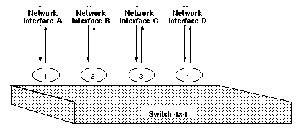
When a switch is included in a HIPPI configuration, each endpoint has a number of hosts with which it can communicate (one at a time). Figure 1-15 illustrates a HIPPI LAN with one switch. The switch in this illustration is a 4 x 4, meaning that the switch can have four systems (8 HIPPI cables) attached to it. The switch supports four simultaneous connections. For example, in Figure 1-15, any one of the following connection scenarios could be occurring at a single point in time:
A and D could be exchanging TCP/IP traffic. There would be two connections open between them. C and B could be doing the same. This scenario opens all four possible connections.
A could be transmitting to B, while B transmitted to C, C to D, and D to A. This scenario also opens four connections.
A and C could be exchanging bidirectional traffic. D could be transmitting to B. Only three connections are open in this scenario.
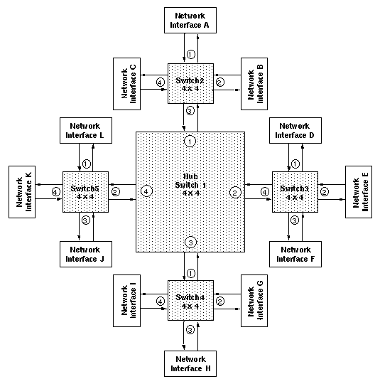
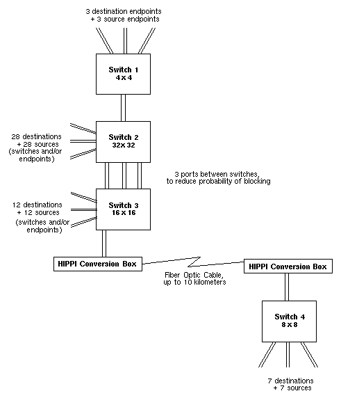
Figure 1-16 illustrates a LAN with multiple switches, and Figure 1-17 illustrates a complex HIPPI LAN including a long distance fiber optic link and multiple ports between switches to improve connection setup time by reducing the probability of encountering a busy link.
The maximum number of switches and endpoints within a LAN is limited by three factors:
When logical routing is used, the 12-bit HIPPI address (half of the Routing Control field) limits the number of unique endpoint addresses to 4096. It is possible for a site to implement this number of networked HIPPI endpoints; however, to be compliant with the HIPPI-SC standard, 64 reserved addresses should not be assigned to local endpoints/hosts. This limits the number of endpoints to 4032 per LAN. There is no limit to the number of switches when logical routing is used.
When source routing is used, the I-field's 24-bit Routing Control field limits the number of port identifiers that can be included in the list. The exact number depends on the sizes of the port identifiers used by the switches along the specific endpoint-to-endpoint path, as explained in Section 1.1.5. Each port identifier in the Routing Control field represents one switch along the path. Table 1-4 summarizes the maximum number of switches along any point-to-point path within a HIPPI LAN, assuming that all switches along that path use port identifiers of the same size. (This assumption does not reflect actual site configuration practices, but is useful here for illustration of a point.) When source routing is used, the number of switches and endpoints that are possible is not limited, but the number of switches between any two endpoints within the LAN is limited.
Table 1-4. Maximum Number of Switches Along Any Single Point-to-pointPath When Using Source Addressing
Number of Bits Used For All Port IDs in Routing Control Field
Max. Number of Switches Along Any Single Point-to-point Path
1
24
2
12
3
8
4
6
5
4
6
4
If a LAN is built according to the guidelines in Appendix B of RFC 1374, the recommended maximum number of hops (switches) between any two endpoints is three. This limit has major implications for the structure and size of a HIPPI LAN. The structure is limited to a single hub switch with satellite switches attached to the hub's ports, but no switches attached to any satellite ports. Figure 1-16 shows an example of a LAN designed in accordance with the RFC 1374 guidelines. Table 1-5 summarizes the maximum number of switches and endpoints possible for a LAN in which switches of only one size are used throughout the LAN.
Table 1-5. Maximum Number of Switches and Endpoints on a LANBuilt in Accordance with RFC 1374, Appendix B Guidelines
4 x 4
8x 8
16 x 16
32 x 32
64 x 64
5 switches /
12 endpoints9 switches /
56 endpoints17 switches /
240 endpoints33 switches /
992 endpoints65 switches /
4032 endpoints
ANSI HIPPI-PH
The HIPPI Mechanical, Electrical, and Signalling (HIPPI-PH) standard defines the physical layer: electrical and mechanical aspects of HIPPI cables, as well as the behavior of HIPPI physical interfaces (including the HIPPI signals, like REQUEST, CONNECT, READY, and PACKET).ANSI HIPPI-SC
The HIPPI Physical Switch Control (HIPPI-SC) standard defines switch behavior, routing methods, and connection management. The HIPPI I-field is defined by this standard.ANSI HIPPI-FP
The HIPPI Framing Protocol (HIPPI-FP) defines data–framing issues: how a packet is formed, how its data contents are described and interpreted. The HIPPI-FP packet (FP header, D1_Data, and D2_Data) is defined by this standard.ANSI HIPPI-LE
The HIPPI Encapsulation of ISO 8802-2 (IEEE 802.2) Logical Link Control Protocol Data Units (HIPPI-LE) standard defines the method for encapsulating (and thus interoperating with) 802.2–compliant data link layers such as FDDI, 802.5 Token Ring, and CSMA/CD (Ethernet).ANSI HIPPI-IPI-3 for Disk
The HIPPI Intelligent Peripheral Interface — Device Generic Command Set for Magnetic and Optical Disk Drives standard defines an upper–layer protocol for interfacing disks to the HIPPI subsystem.ANSI HIPPI-IPI-3 for Tape
The HIPPI Intelligent Peripheral Interface — Device Generic Command Set for Magnetic Tape Drives standard defines an upper–layer protocol for interfacing tapes to the HIPPI subsystem.RFC 1374
IP and ARP on HIPPI, by J. Renwick and A. Nicholson (October 1992) recommends a standards track protocol for using the IP suite of network and transport layer protocols over HIPPI.
The ANSI documentation for HIPPI standards is maintained by the American National Standard of Accredited Standards Committee (ANSI X3T9.3). Copies of the ANSI standards listed above can be obtained by writing or calling the following:
Don Tolmie, Chairperson
Los Alamos National Laboratory
C-5, MS-B255
Los Alamos, NM 87545
Telephone: 505-667-5502
Internet email: [email protected]
This section provides a brief description of the IRIS HIPPI hardware.
The IRIS HIPPI product consists mainly of the following hardware components:
FCI mezzanine (FMezz) board
FCI cable
HIPPI Board
Of the hardware components, only the HIPPI board contains logic specific to the HIPPI protocol. The HIPPI board communicates with another HIPPI node (device) through the HIPPI connectors on the CHALLENGE or Onyx system's I/O panel. The HIPPI board communicates with the CHALLENGE or Onyx systems's operating system through the IBus, using a Flat Cable Interface (FCI) between the HIPPI board and the mezzanine (FMezz) board. The mezzanine board, installed onto any IO4 board, provides access to the IBus. Figure 1-18 illustrates how the HIPPI hardware looks when all the parts are connected together. (The relationships and positioning is different for each configuration, but the overall connections are the same for all installations.)
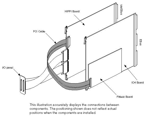
The FCI mezzanine (FMezz) board shipped with the IRIS HIPPI package occupies one short mezzanine slot on any IO4 board. It is not necessary to use this shipped board; the HIPPI board can be attached to any standard FMezz board (long or short). A long FMezz board provides connections for I/O adapters 2 and 5 (lower mezzanine position), or 3 and 6 (upper position) on the IO4 board's IBus; the short mezzanine board provides connections for I/O adapters 5 or 6. (See the "Theory of Operations" chapters in the CHALLENGE/Onyx Deskside Installation Instructions or CHALLENGE/Onyx XL Rackmount Installation Instructions for further details on the IBus, IO4 boards, and I/O adapters.)
The FCI (flat cable interface) cable connects the HIPPI board to the FCI mezzanine (FMezz) card, thus providing the data path between the HIPPI board and the IBus.
The HIPPI board is a 9U VME form factor printed circuit board supporting two HIPPI channels (receive and transmit) that exchange data with ANSI HIPPI–compliant stations and switches. It occupies one VMEBus slot, where it obtains power. The HIPPI board does not use the VMEBus protocol or data path; it uses the FCI cable (connecting to the IBus) for all communication with the local host system. The HIPPI board contains logic that allows it to function as an I/O adapter on any IO4 board's IBus. HIPPI data traverses the following path: HIPPI I/O port, internal HIPPI cable, HIPPI board, FCI cable, FMezz card, IBus on IO4 board, Ebus, host memory.
Because it resides in a VMEBus slot, the HIPPI board has many features of a standard VMEBus board; however, because it is not a VMEBus device, it is also different in many respects. The most important similarities and differences are listed below:
Similarities
The HIPPI board has VMEBus P1, P2, P3 connectors.
When installed, it jumpers its VMEBus slot, thus making the bus signals available to VMEBus boards that are installed downstream from it.
Its VMEBus slot must be serviced by the card cage's power modules.
Differences
The HIPPI board's throughput is not restricted to VMEBus data rates.
The HIPPI board does not require the services of a VCAM board.
It does not use the VMEBus protocol, so does not need to be configured for VMEBus parameters such as interrupt level, bus grant/request priority levels, and VME address.
The IRIS HIPPI board typically uses 75 watts of power, drawn from its VMEBus slot. The board requires 5 volts at a maximum of 15 amps and 12 volts at a maximum of 1.5 amps.
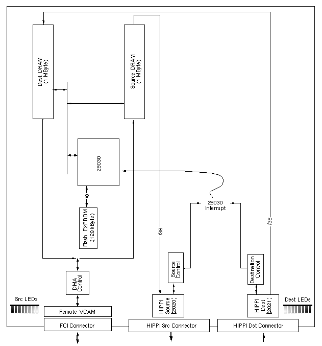
Figure 1-19 is a block diagram of the HIPPI board, showing the main data paths for the board. The board has separate banks of on-board memory (triple-port DRAM) for buffering data between the host and each autonomous HIPPI channel. The board also has a Flash E2PROM that holds the HIPPI firmware and the board's diagnostics; the firmware can be rewritten (upgraded) by the driver if it is found to be out of date when the driver is initialized.