This chapter explains how to set up IRIS FailSafe system for which at least one of the servers is a Challenge S. The process consists of
installing the software
setting up component systems
cabling the private and public networks
setting up the IRIS FailSafe serial connection
testing the installed IRIS FailSafe hardware
testing the serial connection
cabling storage systems
setting the IRIS FailSafe host SCSI IDs
configuring and testing the system
 | Note: Before installing a IRIS FailSafe system, particularly one involving larger Challenge servers and vaults, make sure that the installation site meets the operating limits and AC power requirements as explained in Chapters 3 and 4 of the CHALLENGE/Onyx Site Preparation Guide. |
The following equipment is required for installation:
installation guides for the component systems:
CHALLENGE S Server Owner's Guide (007-2314-003)
Getting Started with XFS Filesystems (007-2549-001)
laptop, ASCII terminal, or IRISconsole
Phillips and small flat-blade screwdrivers
Follow instructions in the latest version of the IRIS FailSafe Administrator's Guide (007-3109-00x) to install the software needed to run IRIS FailSafe.
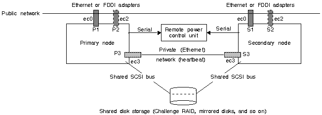
For the IRIS FailSafe system, you must set up
servers
shared storage system
public network interface: one or two per node
private (heartbeat) network interface (Ethernet 10-Base-T port): one per node
shared SCSI buses to shared storage: two per node for mirroring
serial connection through the remote power control unit: one per node
Figure 3-1 diagrams basic IRIS FailSafe cabling.
To set up the component systems, follow these guidelines:
Make sure that the installation site meets the operating limits and AC power requirements of the equipment.
Note: If an L-class Challenge server is involved, follow guidelines in Section 2.2, "Setting Up the Component Systems," in Chapter 2. Prepare the physical location to allow for space, air flow, and floor-loading requirements for all component systems.
Use only the cables included in the shipment. Plan to situate the servers and vaults fairly close together. Differential SCSI cables, including cabling inside the chassis, should be no longer than 60 feet (18.3 meters).
Note: Although the SCSI bus absolute length limit is 80 feet, exceeding 60 feet is not recommended. Make sure the site meets safety and operating considerations.
Prepare the site for the systems' electrical requirements.
Install the second network adapter (ec2) in the Challenge S server if necessary. Follow instructions in the CHALLENGE S Server Owner's Guide.
Set up the shared storage system.
For testing, have ready a laptop or ASCII terminal and keyboard.
Make provisions for the network connections, such as obtaining Ethernet drop cables.
Figure 3-2 shows the ports on the Challenge S server for the private and public network interfaces and for the fast and wide SCSI interface (for the Challenge RAID or Challenge Vault storage system).
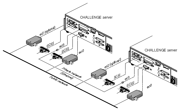
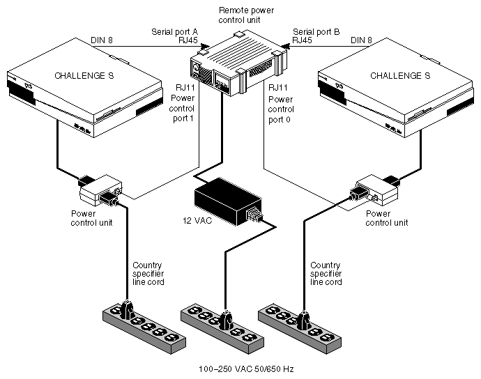
Figure 3-3 shows an example of serial connection for sites using two Challenge S servers.
This section explains
cabling the private network
cabling the public network(s)
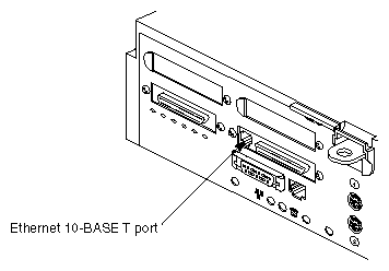
The private network between the Challenge servers supplies the heartbeat of one of the servers to the other. To cable the private network, connect the Ethernet 10-Base-T (ec3) ports on the Challenge S servers to each other with the Ethernet loopback cable supplied with the IRIS FailSafe product.
This port is between the two SCSI connectors on the back of the Challenge S server, as shown in Figure 3-4. Note that the Ethernet 10-Base-T port and the ISDN port below it look similar. The Ethernet 10-Base-T port is the one on top, immediately next to the SCSI connector, as shown in Figure 3-4.
Figure 3-4. Connecting an Ethernet 10-Base-T Cable to the Challenge S Server (S-100 and S-150 Models) for the Private Network (Heartbeat)
 |
If one node in the configuration is a Challenge DM, L, or XL, an external 10-base T transceiver is required. For example, in a Challenge L-Challenge S configuration, plug the Ethernet null-modem cable into the 10-Base-T port on the Challenge S server and the other end into a 10-Base-T transceiver, which in turn is connected to the Ethernet port on the Challenge L server.
Connect the public network drop cable to the Ethernet AUI port (ec0) on the back of the Challenge S server.
In the Challenge S server, you can configure a single FDDI adapter, which takes up both GIO slots. Thus, if you use FDDI you can have only one connection to the public network.
The serial connection between the two Challenge servers in the IRIS FailSafe system makes it possible for one server to reboot the other in case of failure. In the case of two larger servers, the Remote System Control port of one server is cabled to a serial port of the other, and vice versa. Because the Challenge S has no Remote System Control port, the Silicon Graphics remote power control unit and its associated power control units take its place for purposes of the serial connection.
This section explains how to cable the servers to the remote power control unit. It gives instructions for
cabling two Challenge S servers
cabling one Challenge S server and a larger Challenge server
Figure 3-3 earlier in this chapter shows an example of serial connection for sites using two Challenge S servers.
| Note: On the remote power control unit, the leftmost Serial Port (A) controls the leftmost Power Control Port (0), and the rightmost Serial Port (B) controls the next Power Control Port (1). Note that the jacks are different for the two types of ports, as shown in Figure 3-5. |
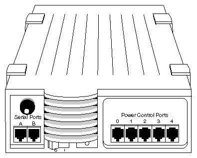
Note that Power Control Ports 2 through 4 are not used; they are supplied with terminator plugs to reduce the chance for error.
If both nodes in your IRIS FailSafe configuration are Challenge S servers, follow these steps:
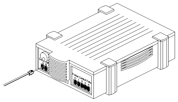
Plug one of the two serial cables included with the remote power control unit that has an RJ45 connector into Serial Port A on the remote power control unit, as shown in Figure 3-6. This cable is labeled CHALLENGE S TO RPCU CABLE.
Note: For all RJ45 and RJ11 connections, be sure the connector is properly seated in the jack so that it makes good contact.
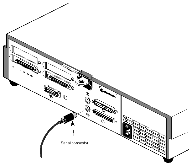
Plug the other end of this serial cable into the serial connector (tty_2) on the back of the Challenge S server, as shown in Figure 3-7.
Plug a serial cable with an RJ11 connector into the Power Control Port 1 on the remote power control unit, as shown in Figure 3-8.
Attach the RJ11 connector of the serial cable to the RJ11 connector in a power control unit, as shown in Figure 3-9.
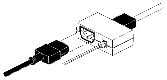
Attach the Challenge S power cable to the same server; plug the other end of the power cable into the power control unit.
Repeat steps 1 through 5 for the second Challenge S server, using Serial Port B and Power Control Port 0.
Make sure that serial port A and Power Control Port 1 are connected (through the remote power control unit) to one Challenge S server, and serial port B and Power Control Port 0 are connected to the other.
Connect the power for the remote power control unit. Power it on; power on the servers and the ASCII terminal or laptop attached to each.
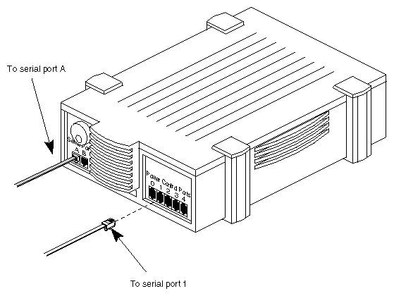
If you are using a Challenge S and a Challenge DM, L, or XL server, follow steps in this section. Figure 3-10 diagrams the serial interface for this configuration.
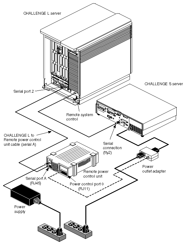
To set up the serial connection for sites using one Challenge S server and another larger Challenge server, follow these steps:
Connect the remote power control unit and the larger Challenge server:
Attach the serial cable (labeled CHALLENGE XL/L TO RPCU CABLE) included with the remote power control unit to RJ45 Serial Port A on the remote power control unit, as shown in Figure 3-6.
Attach the other end of this cable to a serial port on the larger Challenge server, shorn as serial port 2 in Figure 3-10.
Attach one end of a serial cable to Power Control Port 0 on the remote power control unit and the other end of the cable to the RJ45 connector of the power control unit. For details, see Section 3.4.1, "Cabling Two Challenge S Servers."
Attach the Challenge S power cable to the server; plug the other end of the power cable into the power control unit.
Connect a serial cable to the serial port on the Challenge S. Attach the other end to the 9-pin Remote System Control port on the larger Challenge server.
To test the IRIS FailSafe hardware installation, attach an ASCII terminal to each server and run hinv. In the output for the Challenge S server, check for
network interfaces, for example:
E++ controller: ec2, version 1
Integral Ethernet: ec3, version 1
Integral Ethernet: ec0, version 1
This example shows the three network interfaces of a dual-active configuration; an active/standby configuration would lack the first line.
shared disks, for example:
Disk drive: unit 5 on SCSI controller 5
Integral SCSI controller 4: Version WD33C95A, differential, revision 0
Integral SCSI controller 0: Version WD33C93B, revision D
Disk drive: unit 1 on SCSI controller 0
Type hinv on each IRIS FailSafe server; the screen should display output similar to the following:
xfs-ha6 14# hinv 1 150 MHZ IP22 Processor FPU: MIPS R4010 Floating Point Chip Revision: 0.0 CPU: MIPS R4400 Processor Chip Revision: 5.0 On-board serial ports: 2 On-board bi-directional parallel port Data cache size: 16 Kbytes Instruction cache size: 16 Kbytes Secondary unified instruction/data cache size: 1 Mbyte Main memory size: 64 Mbytes Integral ISDN: Basic Rate Interface unit 0, revision 1.0 E++ controller: ec2, version 1 Integral Ethernet: ec3, version 1 Integral Ethernet: ec0, version 1 Integral SCSI controller 5: Version WD33C95A, differential, revision 0 Disk drive: unit 5 on SCSI controller 5 Integral SCSI controller 4: Version WD33C95A, differential, revision 0 Integral SCSI controller 0: Version WD33C93B, revision D Disk drive: unit 1 on SCSI controller 0 |
Make sure the Remote Power Control unit is powered on.
Test the serial connection as explained in Section 2.6, "Testing the Serial Connection," in Chapter 2.
Figure 3-11 shows the Challenge S differential SCSI port connection.
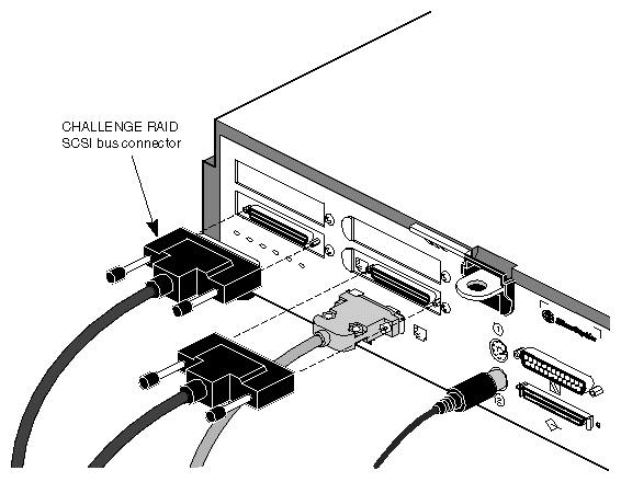
To cable the Challenge Vault or Challenge RAID storage system, follow instructions in Section 2.7, "Cabling the Vaults," and Section 2.8, "Cabling the Challenge RAID Storage System to the Challenge Servers," in Chapter 2.
Follow instructions in Section 2.9, "Setting the IRIS FailSafe Host SCSI IDs," in Chapter 2.