This chapter explains how to set up and cable the two Challenge DM, L, or XL servers (IRIS FailSafe hosts) and the Challenge RAID or vault for use as the hardware for the IRIS FailSafe system.
For information on cabling IRIS FailSafe systems that include one or more Challenge S servers, see Chapter 3, "Setting Up and Cabling the IRIS FailSafe System With Challenge S Servers."
The process consists of
installing the software
setting up the component systems
upgrading the Remote System Control firmware, if necessary
cabling the private and public networks
cabling the Challenge server serial connection
testing the serial connection
cabling the vault(s)
cabling the Challenge RAID storage system(s)
setting the IRIS FailSafe host SCSI IDs
configuring and testing the system
 | Note: Before installing an IRIS FailSafe system, make sure that the installation site meets the operating limits and AC power requirements as explained in Chapters 3 and 4 of the CHALLENGE/Onyx Site Preparation Guide. |
The following equipment is required for installation:
installation guides for the component systems (see "About This Guide" for part numbers)
CHALLENGE/Onyx Site Preparation Guide
CHALLENGE/Onyx XL Rackmount Installation Instructions
CHALLENGE/Onyx L Deskside Installation Instructions
FDDIXpress Mezzanine Board for CHALLENGE and Onyx Installation Instructions
FDDIXpress Administration Guide; included in FDDI board shipment
FDDIXpress Release Notes; included in FDDI board shipment
CHALLENGE RAID Installation and Maintenance Instructions
CHALLENGE Vault L Installation Instructions
CHALLENGE Vault Rack and SCSIBox 2 Installation Instructions
laptop, ASCII terminal, or IRISconsole
Phillips and small flat-blade screwdrivers
Follow instructions in the latest version of the IRIS FailSafe Administrator's Guide (007-3109-00x) to install the software needed to run IRIS FailSafe.
Read through the CHALLENGE/Onyx Site Preparation Guide before unpacking equipment at the site. Follow instructions in that manual, specifically:
Make sure that the installation site meets the operating limits and AC power requirements as explained in Chapters 3 and 4 of the CHALLENGE/Onyx Site Preparation Guide.
Make sure required tools and personnel are on hand for unloading and opening crates and for moving large systems.
Prepare the physical location to allow for space, air flow, and floor-loading requirements for all component systems, as explained in Chapter 3 of the CHALLENGE/Onyx Site Preparation Guide.
Use only the cables included in the shipment. Plan to situate the servers and vaults fairly close together. Differential SCSI cables, including cabling inside the chassis, should be no longer than 60 feet (18.3 meters).
Note: Although the SCSI bus absolute length limit is 80 feet, exceeding 60 feet is not recommended. When cable lengths exceed 60 feet, problems can occur on the SCSI mezzanine card, the IO4B board, or both. Make sure the site meets safety and operating considerations, as explained in Chapter 3 of the CHALLENGE/Onyx Site Preparation Guide.
Prepare the site for the systems' electrical requirements, as explained in Chapter 4 of the CHALLENGE/Onyx Site Preparation Guide.
Connect your laptop or ASCII terminal and keyboard to the first Challenge server, as explained in the server installation instructions.
Connect the power cord for the first IRIS FailSafe host. Turn on the main power switch on the back of the unit; turn on the laptop or ASCII terminal. If necessary, see the server installation instructions for details.
On the IRIS FailSafe host, turn the System Controller key switch to the On position. When power-on diagnostics are completed, a login prompt appears on the console.
Type hinv on each IRIS FailSafe host. In the output, look for the installed shared disks and network interfaces.
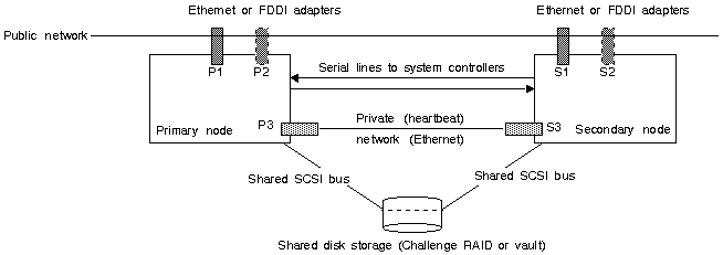
For the IRIS FailSafe system, you are setting up these networks on each server:
public network interface(s)
This network connects the IRIS FailSafe server to clients and the outside world.
serial connection between Remote System Control port and a serial port
If one node fails, this connection enables the surviving node to power-cycle the other.
private (heartbeat) network (Ethernet)
This network, going only between the two nodes, is used exclusively for the keep-alive heartbeat that the two nodes use for monitoring each other's status.
shared SCSI connection to storage
Figure 2-1 diagrams a basic IRIS FailSafe configuration. Note the four types of connections.
Consult with the customer on the number and type of public network interface(s) for each server. If a server has two public network interfaces, they can be on the same network or two different networks.
The IRIS FailSafe system requires that the Challenge DM/L/XL system be running Remote System control port version 3.10 or higher. To verify the PROM version, type sysctlrd -p at the IRIX prompt:
% sysctlrd -p As of Wed Dec 6 23:20:37 1995 Display type: 20 x 2 48.0V supply = 48.00 12.0V supply = 12.00 5.0V supply = 5.20 1.6V supply = 1.64 -5.2V supply = -5.30 -12.0V supply = -13.00 System air temp = 28.00 C Blower A speed = 1136 RPM Firmware version 3.10 -- Extrema since power-up -- Max temp = 30.00 Min temp = 28.00 Max blower A speed = 1190 Min blower A speed = 112 |
The command listing displays the firmware version, as shown above in the sixth line from the bottom.
If you must upgrade to firmware version 3.10, use the new system controller firmware PROM kit(s). Follow instructions in the System Controller PROM Upgradefor Oracle Parallel Server document (108-0140-001), included in this shipment.
This section explains network cabling:
installing FDDI boards in the IRIS FailSafe hosts for a public network connection
cabling the private network
setting up a public network Ethernet connection
| Note: For the public network connection, both connections must be of the same type: both Ethernet or both FDDI. Otherwise, failover does not work. |
This section explains using (optional) FDDI to connect to the network.
Have the latest versions of the following manuals at hand:
FDDIXpress Release Notes
FDDIXpress Administration Guide
FDDIXpress Mezzanine Board for CHALLENGE and Onyx Installation Instructions
To install the FDDI boards in the servers, follow these steps:
Check the contents of the FDDI board shipment, as explained in Chapter 1 of the FDDIXpress Mezzanine Board Installation Instructions.
Use the versions command to check if the system into which you are installing the FDDIXPress™ mezzanine board is already running FDDIXPress software. If FDDIXPress is not installed, install it following instructions in the FDDIXpress Release Notes.
Install the FDDIXpress board following instructions in Sections 2.1 and 2.2 in Chapter 2 (Challenge L) or Sections 3.1 and 3.2 in Chapter 3 (Challenge XL) of the FDDIXpress Mezzanine Board for CHALLENGE and Onyx Installation Instructions.
Cable the connections and complete the installation as explained in Chapter 4 of the FDDIXpress Mezzanine Board for CHALLENGE and Onyx Installation Instructions.
The private network between the Challenge servers supplies the heartbeat of one of the servers to the other. To cable the private network, connect the Ethernet 10-Base-T (ec0) ports on the Challenge servers to each other with the Ethernet loopback cable supplied with the IRIS FailSafe system (018-0543-001). For the Challenge L, which does not have any 10-Base-T ports, use a transceiver.
Connect the public network drop cable to the Ethernet AUI port or to an optional Ethernet port on each Challenge server. For the Challenge L, which does not have any 10-BASE-T ports, use a transceiver if necessary. For information on installing an E-Plex board, see POWER Channel E-Plex Installation Instructions (108-0114-00x).
Cross-cable the Remote System Control port to a serial port on the Challenge servers for the serial connection between the two. Follow these steps:
Attach a serial cable to a serial port on the first IRIS FailSafe host.
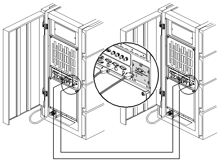
Connect the other end of this cable to the 9-pin Remote System Control connector on the second IRIS FailSafe host, as shown in Figure 2-2.
Attach the other serial cable in the kit to the first host's Remote System Control connector and a serial port (for example, tty_2) on the second host. Figure 2-2 shows the serial cabling.
To test the serial connection between the IRIS FailSafe servers, follow these steps:
Make sure the IRIS FailSafe servers are powered on.
Enter
/etc/init.d/failsafe stop
Test the connection; for example, if the serial cable was connected to tty_2, enter
/usr/etc/ha_spng -i 10 -f /dev/ttyd2
No output appears; check the return value of the command. If the return value is 0, the connection is good.
If the return value is 1:
verify that the IRIS FailSafe server is powered on
verify the cable connections from one server's serial port or remote power control unit and the other server's System Console port
Repeat the process on the second node.
If results are unsatisfactory, make sure that the RJ connector is completely seated at both ends and is making good contact.
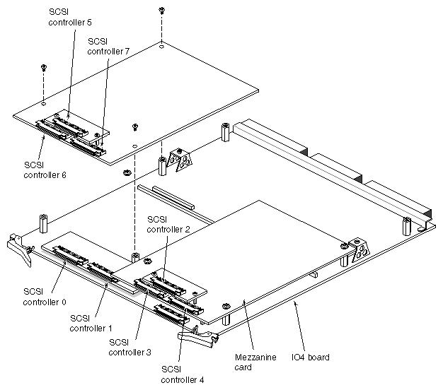
The numbering of SCSI controllers (ports) on the IRIS FailSafe host IO4 board and mezzanine card(s) (daughter boards), if present, is standardized. Figure 2-3 diagrams the numbering scheme. Note that the numbering is constant regardless of which daughter board is installed.
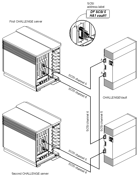
In an IRIS FailSafe configuration, each SCSI bus runs from a controller on one Challenge server through a vault (or Challenge RAID) to the second IRIS FailSafe host. Figure 2-4 shows IRIS FailSafe vault cabling.
To cable the SCSI buses on the vaults to each IRIS FailSafe host, follow these steps:
Power off both servers and the vaults.
On the back of the vault, insert one of the cables into the top SCSI channel A socket, as shown in Figure 2-4.
Connect the other end of this cable to a SCSI bus port on the first IRIS FailSafe host (for example, DF SCSI 5), as shown in Figure 2-4. Label the connector and cable end.
Insert a cable into the lower SCSI channel A port on the back of the vault. Label the cable end.
Connect the other end of this cable to the same SCSI bus port on the second IRIS FailSafe host that you used on the first host (shown as DF SCSI 5 in Figure 2-4).
Do a dummy I/O to test each link. For example, from the first host, read data on disk 8 on SCSI bus 5 (dks5d8) to see if the disk light for disk 8 on the vault lights up. Repeat this test from the second IRIS FailSafe host and check if the same LED is activated.
Table 2-1 charts SCSI ID switch settings for the Challenge RAID storage system.
| Note: Challenge RAID SCSI ID switch settings do not conform to frequently used numbering schemes. |
Table 2-1. Challenge RAID SCSI ID Switch Settings
SCSI ID Number | Switch Number |
|
|
|
|---|---|---|---|---|
| ID 0 | ID 1 | ID 2 | ID 3 |
1 | Off | On | On | On |
2: Do not use | On | Off | On | On |
3 | Off | Off | On | On |
4 | On | On | Off | On |
5 | Off | On | Off | On |
6 | On | Off | Off | On |
7 | Off | Off | Off | On |
8 | On | On | On | Off |
9 | Off | On | On | Off |
10 | On | Off | On | Off |
11 | Off | Off | On | Off |
12 | On | On | Off | Off |
13 | Off | On | Off | Off |
14 | On | Off | Off | Off |
15 | Off | Off | Off | Off |
To cable the Challenge RAID storage system to the Challenge servers, follow these steps:
Have ready four 20-foot (or shorter) SCSI cables. Figure 2-5 shows the Challenge RAID SCSI ports.
On the back of the Challenge RAID storage system, attach a SCSI cable to the Challenge RAID SCSI A in port, as shown in Figure 2-6.
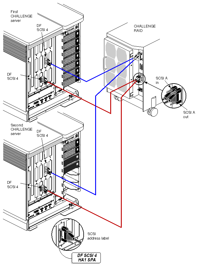
Connect the other end of this cable to a SCSI bus (for example, DF SCSI 4) on the first host, as shown in Figure 2-7.
On the back of the Challenge RAID storage system, attach another SCSI cable to the Challenge RAID SCSI A out port.
Connect the other end of this cable to a SCSI bus (for example, DF SCSI 4) on the second host.
Repeat steps 2 through 5 for the SCSI B port on the Challenge RAID storage system.
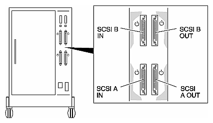
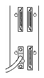
Figure 2-7 shows connections for Challenge RAID and servers in an IRIS FailSafe configuration.
The two Challenge servers must have different SCSI IDs. The recommended addresses for an IRIS FailSafe system are 0 for the first IRIS FailSafe host and 2 for the second IRIS FailSafe host, assuming that this node has only one internal drive.
| Note: SCSI host address conflicts are a frequent cause of problems getting IRIS FailSafe up and running. Each bus must be free of duplicate SCSI IDs. You might want to diagram the SCSI bus layout of the entire cluster, including the internal buses. The SCSI ID of each host is present on every bus to which it is attached. |
Setting the host SCSI IDs consists of these steps:
On the first IRIS FailSafe host, enter the command nvram. The last line of this command's output should contain the line
scsihostid=0
This output can also appear without any numeral after the equals sign, which means that the SCSI host ID for this IRIS FailSafe host is 0.
On the second IRIS FailSafe host, repeat step 1 in the second window. The last line of the output should be scsihostid=2, meaning that the SCSI host ID for the second IRIS FailSafe host is 2.
If the second IRIS FailSafe host's SCSI host ID is not 2 (probably the case), follow these steps:
Reboot and start the system. Press <Esc> to bring up the System Maintenance Menu; choose item 5, the Command Monitor.
In the Command Monitor, set the SCSI ID for this system:
setenv scsihostid 2
init
The command init sets the value into the PROM. Choose item 5 again to return to the PROM monitor.

Caution: No SCSI device on any bus on the second server should have SCSI ID 2. To verify that the SCSI ID was set, enter
printenv
The output should include the line scsihostid=2.
Exit the System Maintenance Menu and restart the system.
Enter the command hinv on the first server.
Enter the command hinv on the second server. Compare the output for each server.