This chapter describes how to install the E-Plex mezzanine board, cables, and connectors into a Challenge or Onyx server or supercomputer. There is a separate section for each of the following platforms:
Challenge, POWER Challenge, Onyx, and POWER Onyx L Deskside
Challenge, POWER Challenge, Onyx, and POWER Onyx XL Rackmount

Before starting the installation, prepare yourself and the equipment by following the instructions below.
Verify that the E-Plex package is complete. It should contain the items listed in Table 2-1.
Table 2-1. E-Plex Package Contents
Item | Quantity | Part Number |
|---|---|---|
E-Plex board | 1 | 034-0590-006 |
60-pin to 60-pin cable, ports 0 through 3 | 1 | 018-0493-001 |
60-pin to 60-pin cable, ports 4 through 7 | 1 | 018-0494-001 |
I/O housing and filter-board plate) assembly | 1 | 013-1255-001 |
I/O housing and filter-board plate) assembly | 1 | 013-1256-001 |
Screws for attaching E-Plex board to IO4 board standoffs | 4 |
|
Screws for attaching E-Plex board to IO4 board standoffs | 4 |
|
Label: Connector IDs | 1 or 2 sheets | 024-0854-002 |
Label Cable wrap IDs | 1 or 2 sheets | 024-0855-002 |
CD-ROMs with software (including online release notes and other information) | 2 |
|
POWER Channel E-Plex Installation Instructions | 1 manual | 108-0114-001 |
POWER Channel E-Plex Software Configuration Guide | 1 manual | 007-2414-001 |
If any of these components are missing, do not proceed with the installation. Notify the customer or the customer's sales representative.
 | Note: The part numbers listed above reflect the E-Plex product when this manual went to press. The part numbers may have been revised since that time. |
Follow the instructions in this section to prepare the system for installation.
 | Caution: This equipment is extremely sensitive and susceptible to damage by electrostatic discharge (ESD), a spark caused by the build-up of electrical static potential on clothing and other material. You must use proper ESD preventive measures as explained in the "Safety" section of the CHALLENGE/Onyx Deskside Installation Instructions and the CHALLENGE/Onyx Rackmount Installation Instructions. |
At a shell prompt, use the versions command to verify that the version of the IRIX operating system is correct for this E-Plex release:
% versions eoe1
I  eoe1  date  Execution Only Environment 1, version
The E-Plex board is supported in IRIX 5.3 and IRIX 6.1 and later.
Verify that any crucial filesystems are backed up.
Certain software patches may be required to make the board fully functional and to fix potential problems. The CD-ROMs included with the board contain the appropriate software patches.
To install the software patches, follow these steps:
If a CD-ROM drive is not already attached to the system, do so now.
Insert the appropriate CD-ROM for the particular version of IRIX (either the 5.3 CD or the 6.1 CD) into the CD-ROM drive.
At a shell prompt, enter this command:
more /CDROM/README_FIRST.txt
The file README_FIRST.txt contains up-to-the-minute information on which patches to apply to various Challenge and Onyx systems and various releases of IRIX. It also contains instructions for installing the patches.
Follow the instructions in the file README_FIRST.txt to install any required patches from the CD.
When you are finished installing patches from the CD-ROM, eject it from the drive.
You are now ready to shut down the system and begin installing the E-Plex board. See Section 2.3, "Where to Go Next."
For complete information on configuring the system for use with the E-plex board, see the POWER Channel E-Plex Software Configuration Guide.
To install the E-Plex board in a deskside system (Challenge L, POWER Challenge L, Onyx L, or POWER Onyx L), go to Section 2.4, "Installing on Challenge and Onyx L Deskside Systems."
To install the E-Plex board in a rackmount system (Challenge XL, POWER Challenge XL, Onyx XL, or POWER Onyx XL), go to Section 2.5, "Installing on Challenge and Onyx XL Rackmount Systems."
This section describes the steps for installing the E-Plex board into a Challenge, POWER Challenge, Onyx, or POWER Onyx L deskside system.
Before shutting down the system, follow the appropriate procedures for notifying any users who are logged in, and for halting the IRIX operating system gracefully. Refer to the IRIX Advanced Site and Server Administration Guide for complete details.
Once the operating system has halted, follow these steps to turn off the system and open the I/O panel:
Shut off the system by turning the key on the System Controller panel (located at the front) to OFF. When the system is off, switch the circuit breaker on the back to OFF. Wait at least one minute for power to drain from the offline switchers (OLSs) before proceeding.
Open the front door and pull down the I/O panel in the front of the chassis to expose the IO4 boards.
Remove the board locks.
You are now ready to examine the available IO4 boards and locate an open mezzanine slot.
To install the E-Plex board, locate an available short mezzanine slot on an IO4 board. When selecting a mezzanine slot, use the following guidelines:
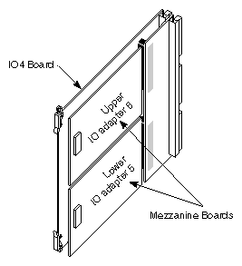
If the system has only one IO4 board, this is the location for the E-Plex board. Although the E-Plex board may be installed in either the upper or lower position on the IO4 board, it is strongly recommended that you install it in the lower slot first, if that slot is available. See Figure 2-1.
If you have a choice of IO4 boards that have open mezzanine slots, keep in mind the potential problems described below:
When the system boots it automatically configures the network interfaces for the E-Plex boards based on their position on the IO4 boards (see Figure 2-1) and on the position of the IO4 boards in the system chassis. The system examines all of the boards at boot time, starting with the main IO4 (slot 5 in Challenge L and slot 3 in the Onyx deskside) and proceeding down the available slots. For the Challenge, this means slot 5, slot 4, slot 3, and slot 2 in that order. There is only one IO4 board in the Onyx deskside.
On each IO4, IO adapter 5 (lower location) is examined first, then IO adapter 6 (upper location.)
The closer any board is placed to IO adapter position 5 on the main IO4 board, the further it is said to be upstream. The farther away from that position it is installed, the farther it is said to be downstream.
If there are two E-Plex boards installed in the system, the one that is furthest upstream is recognized and configured first.
Install the first E-Plex board as far upstream as possible, especially if you are installing only one E-Plex board at this time. It will be extremely inconvenient if you later install another E-Plex board upstream of the first board, because when the system boots it will automatically reconfigure the network interfaces for the first board. This will force you to either switch network cables between the two boards or change the network configuration (which potentially involves editing nine or ten files.) It is better to avoid these problems by installing the first E-Plex board as far upstream as possible.
For a complete description of the difference between upstream and downstream boards and how their positions affect the way that their network interfaces are configured by IRIX, and how to reconfigure the network interface, see the POWER Channel E-Plex Software Configuration Guide.
If there are no unoccupied mezzanine slots, you must install another IO4 board. Contact the sales representative to order one. The installation cannot be continued until a mezzanine slot is available.
Note: You can install a maximum of four IO4 boards in a Challenge L, and a maximum of one IO4 board in an Onyx deskside system. If the maximum number of IO4 boards are already installed, and if all the mezzanine slots are occupied, an E-Plex board cannot be installed in the system.
Follow the steps below to install the E-Plex mezzanine board.
Remove the IO4 board that you have selected from the deskside chassis.
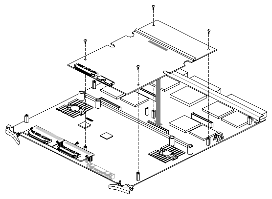
Lay the board on a flat antistatic surface so that the component side faces up and the SCSI connectors face toward you, as illustrated in Figure 2-2.
Locate the selected mezzanine slot (upper or lower), as illustrated in Figure 2-2.
Position the E-Plex board onto the selected slot so that the connector on the bottom of the card matches the mezzanine board receptacle on the IO4 board and the standoffs match the card's holes. Figure 2-2 illustrates the correct positioning for the lower slots.
Install the screws shipped with the E-Plex board. The IO4 board standoffs have a "float" feature, so the screws do not tighten completely.
Label the E-Plex cables (cable 0 and cable 1). Use the appropriate labels from the E-Plex cablewrap label sheet.
If there is already an E-Plex board installed in the system, and you are installing an additional E-Plex, you should relabel the upper and lower I/O housing. (The default labels applied at the factory are for the first E-Plex board in the system.)
From the sheet of labels, remove the ones with the identification for a second E-Plex board (ep10 through ep13, and ep14 through ep17). Apply these on the appropriate I/O housing. The label with ep10 through ep13 should cover ep0 through ep3, and the label with ep14 through ep17 should cover ep4 through ep7.
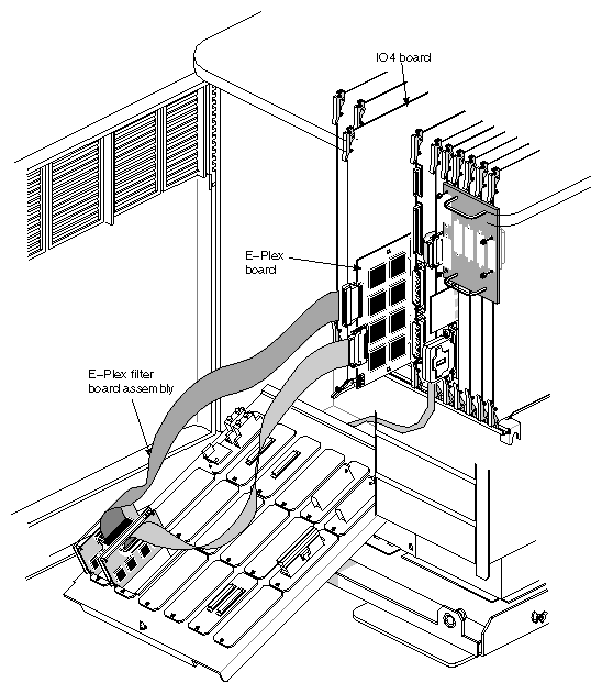
Reinstall the IO4 board into the chassis, as illustrated in Figure 2-3. Push the board firmly into the backplane. If the IO4 has a VCAM or GCAM board, these boards must also connect to the backplane.
Locate the upper I/O housing and filter assembly (which has ports ep4 through ep7) and its connector cable (cable 1).
Attach cable 1 (which has a 60-pin male connector) to the upper I/O housing and filter assembly.
Attach cable 0 (which has a 60-pin female connector) to the lower I/O housing and filter assembly.
Remove two blank panel plates from the system's I/O panel and install the E-Plex I/O housings.
| Note: Because of the depth of the I/O housing and filter assembly, we recommend that you install the assemblies in the upper row of I/O panel openings in Deskside systems (as shown in Figure 2-3). If one of the I/O housings and filter assemblies is installed in the bottom row of the I/O panel, you may not be able to install or remove a board in the slot directly behind that E-Plex I/O housing unless you remove the housing first. |
Attach cables 0 and 1 to the appropriate connectors on the E-Plex board. The connectors are keyed so that it is impossible to install them incorrectly.
Close the I/O door(s) and the chassis doors.
Attach any Ethernet cables, as required.
Make sure the network address used on each cable is correct for the port, as configured in the software configuration files. (See the POWER Channel E-Plex Software Configuration Guide.)
The hardware installation is complete. The finished installation should look similar to Figure 2-3.
To finish the installation, follow these steps:
Switch the circuit breaker on the back of the chassis to ON, then turn the key switch on the front to ON.
You should eventually see the System Maintenance Menu. Select option 1 to start the system.
As the system boots, you should see some messages about the kernel being automatically rebuilt.
Note: If you do not see these messages, it means you have not installed the E-Plex software. When the system has completed booting, log in as root.
If you have not done so already, use either inst or swmgr to install the E-Plex software. See Section 2.2, "Installing Software." After installing the E-Plex software, reboot the system using the reboot command.
Once the E-Plex software is installed, make sure the board is recognized by the system using the hinv command:
% /sbin/hinv
. . .
I/O board, Ebus slot#: IO4 revision x
. . .
E-Plex Ethernet controller: ep0-7, slot 3, adapter 5, firmware 9503202300
. . .
This example shows a single E-Plex board installed in slot 3, adapter position 5.
Note: If the board is not listed, reinstall the product (both boards and all cables), making sure everything is firmly seated and tightly connected.
You are finished installing the E-Plex board.
If you have not done so already, turn to the POWER Channel E-Plex Software Configuration Guide to configure the network interfaces.
This section describes the steps for installing the E-Plex board into a Challenge, POWER Challenge, Onyx, or POWER Onyx XL Rackmount system.
Before shutting down the system, follow the appropriate procedures for notifying any users who are logged in, and for halting the IRIX operating system gracefully. Refer to the IRIX Advanced Site and Server Administration Guide for complete details.
Once the operating system has halted, follow these steps to turn off the system and open the I/O panel:
Shut off the system by turning the key on the System Controller panel (located at the front) to OFF. When the system is off, switch the circuit breaker on the back to OFF. Wait at least one minute for power to drain from the offline switchers (OLSs) before proceeding.
Open the front door and pull down the I/O panel in the front of the chassis to expose the IO4 boards.
Remove the board locks.
You are now ready to examine the available IO4 boards and locate an open mezzanine slot.
To install the E-Plex board, you need to locate an available short mezzanine slot on an IO4 board. When selecting a mezzanine slot, use the following guidelines:
If the system has only one IO4 board, this is the location for the E-Plex board. Although the E-Plex board may be installed in either the upper or lower position on the IO4 board, it is strongly recommended that you install it in the lower slot first, if that slot is available. See Figure 2-4.
If you have a choice of IO4 boards that have open mezzanine slots, keep in mind the potential problems described below:
When the system boots it automatically configures the network interfaces for the E-Plex boards based on their position on the IO4 boards (see Figure 2-4) and on the position of the IO4 boards in the system chassis. The system examines all of the boards at boot time, starting with slot 15 (Challenge) or slot 11 (Onyx), and proceeding down the available slots.
On each IO4, IO adapter 5 (lower location) is examined first, then IO adapter 6 (upper location.)
The closer a board is placed to IO adapter location 5 on the main IO4 board, the further it is said to be upstream. The farther away from that location it is installed, the farther it is said to be downstream.
If there are two E-Plex boards installed in the system, the one that is furthest upstream is recognized and configured first.
Install the first E-Plex board as far upstream as possible, especially if you are installing only one E-Plex board at this time. It will be extremely inconvenient if you later install another E-Plex board upstream of the first board, because when the system boots it will automatically reconfigure the network interfaces for the first board. This will force you to either switch network cables between the two boards or change the network configuration (which potentially involves editing nine or ten files.) It is better to avoid these problems by installing the first E-Plex board as far upstream as possible.
For a complete description of the difference between upstream and downstream boards and how their positions affect the way that their network interfaces are configured by IRIX, and how to reconfigure the network interface, see the POWER Channel E-Plex Software Configuration Guide.
If there are no unoccupied mezzanine slots, you must install another IO4 board. Contact the sales representative to order one. The installation cannot be continued until a mezzanine slot is available.
Note: You can install a maximum of six IO4 boards in a Challenge XL, and a maximum of four IO4 boards in an Onyx rackmount. If all IO4 boards are already installed, and if all the mezzanine slots are occupied, an E-Plex board cannot be installed in this system.
Follow the steps below to install the E-Plex mezzanine board.
Remove the IO4 board that you have selected from the rackmount chassis.
Lay the board on a flat antistatic surface so that the component side faces up and the SCSI connectors face toward you, as illustrated in Figure 2-5
Locate the selected mezzanine slot, as illustrated in Figure 2-5.
Position the E-Plex board onto the selected slot so that the connector on the bottom of the card matches the mezzanine board receptacle on the IO4 board and the standoffs match the card's holes. Figure 2-5 illustrates the correct positioning for the lower slot on an IO4.
Install the screws shipped with the E-Plex board. The IO4 board standoffs have a "float" feature, so the screws do not tighten completely.
Label the E-Plex cables (cable 0 and cable 1). Use the appropriate labels from the E-Plex cablewrap label sheet.
If there is already an E-Plex board installed in the system, and you are installing an additional E-Plex, you should relabel the upper and lower I/O housing. (The default labels applied at the factory are for the first E-Plex board in the system.)
From the sheet of labels, remove the ones with the identification for a second E-Plex board (ep10 through ep13, and ep14 through ep17). Apply these on the appropriate I/O housing. The label with ep10 through ep13 should cover ep0 through ep3, and the label with ep14 through ep17 should cover ep4 through ep7.
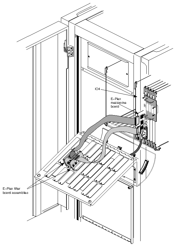
Reinstall the IO4 board into the chassis, as illustrated in Figure 2-6. Push the board firmly into the backplane. If the IO4 has a VCAM or GCAM board, these boards must also connect to the backplane.
Locate cable 1 and the upper I/O housing (which has ports ep4 through ep7).
Attach cable 1 (which has a 60-pin male connector) to the upper I/O plate and filter assembly.
Locate cable 0 (which has a 60-pin female connector) and attach it to the lower I/O housing.
Remove two blank panel plates from the middle row of the system's I/O panel and install the E-Plex housings.
| Note: Because of the size of the I/O housing and filter assembly, we recommend that you install the assemblies in the middle row of I/O panel openings on Rackmount systems (as shown in Figure 2-6). If the I/O housings and filter assemblies are installed in an upper row of the I/O panel, the filter assembly circuit boards can strike the upper edge of the cardcage opening and become damaged. If they are installed in the bottom row of the I/O panel, you may not be able to install or remove a board in the slot directly behind that E-Plex I/O housing unless you remove the housings first. |
Attach cable 0 and cable 1 to the E-Plex board.
Close the I/O door(s) and the chassis doors.
Attach any Ethernet cables, as required.
Make sure the network address used on each cable is correct for the port, as configured in the software configuration files. (See the POWER Channel E-Plex Software Configuration Guide.)
The hardware installation is complete. Figure 2-6 shows the completed installation.
To finish the installation, follow these steps:
Switch the circuit breaker on the back of the chassis to ON, then turn the key switch on the front to ON.
You should eventually see the System Maintenance Menu. Select option 1 to start the system.
As the system boots, you should see some messages about the kernel being automatically rebuilt.
Note: If you do not see these messages, it means you have not installed the E-Plex software. When the system has completed booting, log in as root.
If you have not done so already, use either inst or swmgr to install the E-Plex software. See Section 2.2, "Installing Software." After installing the E-Plex software, reboot the system using the reboot command.
Once the E-Plex software is installed, make sure the board is recognized by the system using the hinv command:
% /sbin/hinv
. . .
I/O board, Ebus slot#: IO4 revision x
. . .
E-Plex Ethernet controller: ep0-7, slot 3, adapter 5, firmware 9503202300
. . .
This example shows a single E-Plex board installed in slot 3, adapter position 5.
Note: If the board is not listed, reinstall the product (both boards and all cables), making sure everything is firmly seated and tightly connected.
You are finished installing the E-Plex board.
If you have not done so already, turn to the POWER Channel E-Plex Software Configuration Guide to configure the network interfaces.