This chapter provides an overview of the E-Plex board and describes various technical details of the board, including the main components and their functions.
The E-Plex board is an intelligent 8-port Ethernet controller. Figure 1-1 shows the basic E-Plex hardware.
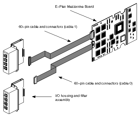
Figure 1-2 shows the layout of the E-Plex board's components.
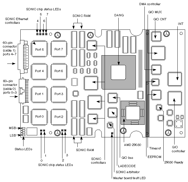
The major components of the E-Plex board are described in Table 1-1.
Table 1-1. Major E-Plex Board Components
Component | Function |
|---|---|
AMD 29030 | Advanced Micro Devices 29030 microprocessor. |
SONICTM | SONIC intelligent Ethernet controllers; one per channel, eight total chips on a single E-Plex board. |
SONIC arbitrator | Arbitrates which SONIC chip communicates with the SONIC memory at a given time. |
SONIC RAM | Memory for use by the SONIC chips. |
DANGTM | Proprietary Silicon Graphics ASIC that interfaces the GIOBusTM to the system. |
EEPROM | PROM containing boot-up software, operating programs, and diagnostic programs for the E-Plex board. |
Master board LED | Indicates the status of the AMD 29030 microprocessor; if the board status light is on steady, the microprocessor is halted and the board is not functioning properly. |
Status LEDs | Used for factory service and testing. |
SONIC chip status LEDs | Indicate the status of the ports controlled by the individual SONIC Ethernet controller chips; blinking green indicates transmit and receive activity; a light that is on solid yellow (or solid red on early version of the board) indicates that the port is not enabled. Note that during periods of intense network activity, the LEDs may blink green so rapidly as to appear to be lit solid. |
Two assemblies, which combine an I/O housing and filtering circuitry, are used with the E-Plex board. These are called the upper and lowerI/O housing and filter-board assemblies. The lower assembly provides 10-Base-T connectors for the first four Ethernet ports, which are labeled ep0 through ep3. The upper assembly provides the second four 10-Base-T connectors, which are labeled ep4 through ep7. Figure 1-3 shows front and rear views of the two I/O and filter-board assemblies that are used with each E-Plex board.
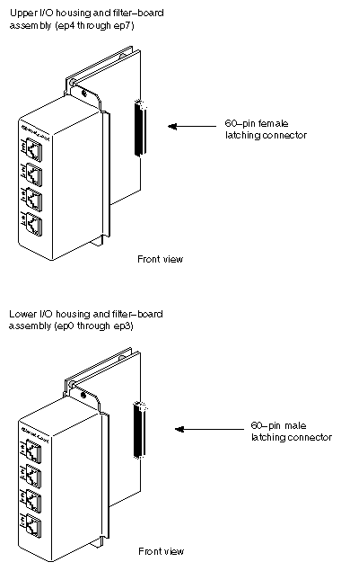
The connector on the rear of each I/O and filter-board assembly is keyed so that it is impossible to attach the connector cables improperly. The connector cables are describes in the next section.
Two cables connect the E-Plex board to the two I/O and filter-board assemblies. These are designated cable 0 and cable 1. Cable 0 connects to ports ep0 through ep3 and cable 1 connects to ports ep4 through ep7. Figure 1-4 shows these cables.
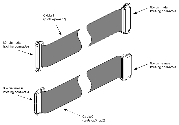
The connectors on each of the cables are keyed so that they cannot be attached to the incorrect I/O and filter-board assemblies.