This chapter discusses how to prepare a physical location for a system:
provide space for the system chassis (including any expansion chassis)
for graphics systems, provide space for local devices: monitor, keyboard, mouse
check the site's environmental factors
consider installation and routine activities
Using the clearance guidelines in this section, select a location that allows proper airflow, cabling, routine activities, and maintenance. As a general rule, use these guidelines to ensure the best system performance. All systems include thermal overrides to prevent damage caused by excessive heat, but an improperly positioned system leads to unnecessary service calls and system downtime.
Every location and system is different, requiring flexibility during installation. This section provides minimum space guidelines for a fully loaded system. The space guidelines can be reduced approximately 10–20 percent for:
systems that are not fully configured, depending on the number and type of devices installed in the chassis
Silicon Graphics systems arranged next to each other
The final test for any system is actual operation, and some adjustments may be required after initial installation.
This section describes the space requirements for these chassis:
deskside
rackmount
Vault
To determine the minimum space requirements for a chassis, add the chassis dimensions shown in Figure 3-1 and the appropriate clearances shown in Table 3-1.
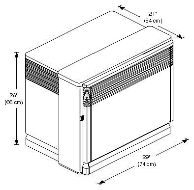
Table 3-1. Deskside Airflow Clearances
Top Clearance | Left Side[a] | Right Sidea | Front | Back |
|---|---|---|---|---|
More than 6" | 3" (8 cm) | ≥ 6" (15 cm) | ≥ 6" (15 cm) | ≥ 6" (15 cm) |
Less than 6" | 6" (15 cm) | ≥ 10" (25 cm) | ≥ 8" (20 cm) | ≥ 8" (20 cm) |
[a] As viewed from the front of the chassis | ||||
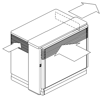
The different clearances are based on the airflow requirements of the chassis. If the top of the chassis is unobstructed, less clearance is required on the sides and back. If the top of the chassis is obstructed, however, the sides and back of the chassis must compensate for the smaller air exhaust path. Figure 3-2 shows the airflow path of the chassis.
Additional space is required to service the chassis, such as connecting or disconnecting cables and changing internal drives, boards, and other components. Be sure to allow sufficient space either in front of or behind the chassis to facilitate future installation, service, and cabling activities. The chassis includes wheels for easier front-to-back movement. See Figure 3-3 for the wheel locations. You can fix the wheels in place by using the chassis levelers or by using a wheel chock (Silicon Graphics part number 040-0220-001).
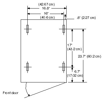
Table 3-2 summarizes the physical requirements of the deskside chassis.
Table 3-2. Deskside Physical Specifications
Parameter | Characteristic |
|---|---|
Dimensions, chassis |
|
26" (66 cm) | |
21" (53.3 cm) | |
29" (73.7 cm) | |
Dimensions, shipping |
|
height | 37" (94 cm) |
width | 32" (81.3 cm) |
depth | 42" (107 cm) |
| |
195 lbs (88.5 kg) | |
300 lbs (136 kg) | |
shipping | 325 lbs (147 kg) |
Provide a location for a rackmount chassis, with clearance for the front and rear cabinet doors in their fully opened positions. The chassis requires minimal side clearances because most of the airflow and servicing is through the front, rear, and top of the chassis. Side access is required to:
remove and install a midplane
remove and install a SCSI box
For activities requiring side access, determine if the chassis can be rolled forward or backward to provide adequate side clearance. If an installation is semipermanent, such as at sites with chassis bolted directly to the floor to prevent movement, allow a total width of 96 inches (244 cm). Use the dimensions shown in Figure 3-4 for rackmount chassis clearance.
Position the chassis so that it receives proper air circulation. See Figure 3-5 for the airflow through the chassis. An ideal location provides cool air near the chassis air intake vents and warm air removal near the chassis air outlets. Air temperature should not fluctuate dramatically, and the air should circulate freely.
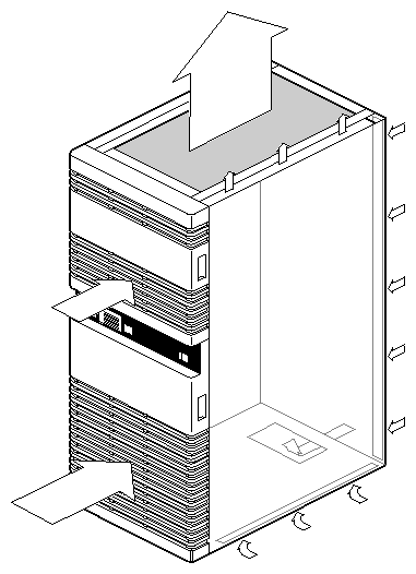
 | Note: Keep the top of the chassis clear of any obstruction. The top of the chassis is the primary air venting surface and is not structurally designed to hold weight. |
Compare the floor-load rating of the site with the values listed in Table 3-3. Some site floor-load ratings are as low as 100 lb/ft2 To ensure that the flooring is adequate for all future chassis upgrades, you must make sure the floor-load rating meets 133 lb/ft2.
Table 3-3. Rackmount Floor-load Requirements
Chassis Configuration | Weight | Floor-load Rating (lb/ft.2) |
|---|---|---|
Minimum | 560 lbs (254 kg) | 62 lb/ft2 (249 kg/m2) |
Maximum | 1,200 lbs (544 kg) | 133 lb/ft2 (533 kg/m2) |
For installations on raised floors, check that the construction will properly support the distribution of the weight. The rackmount chassis uses four casters and four stabilizing levelers that distribute the weight load to the site floor. See Figure 3-6 for the caster and leveler locations. If a floor is modified, such as by cutting new access panels in computer floor tiles, determine if additional reinforcement is required.
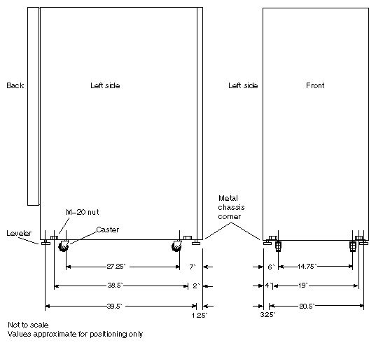
Table 3-4 summarizes the physical requirements of the rackmount chassis.
Table 3-4. Rackmount Physical Specifications
Parameter | Characteristic |
|---|---|
Dimensions, chassis |
|
62.3" (159 cm) | |
27" (69 cm) | |
48" (122 cm) | |
Dimensions, shipping |
|
height | 74.5" (189 cm) |
width | 46" (117 cm) |
depth | 59.5" (151 cm) |
| |
560 lbs (254 kg) | |
1,200 lbs (544 kg) | |
1,500 lbs (680 kg) | |
| |
height | 15" (38 cm) |
width | 17.345" (44 cm) |
depth | 19" (48.3 cm) |
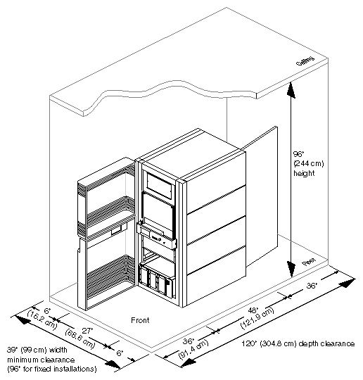
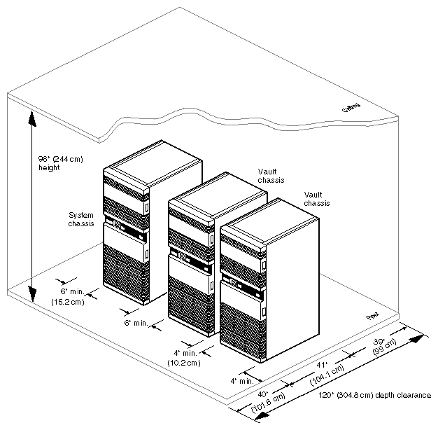
Position a Vault chassis with the clearances shown in Figure 3-7. The side clearances allow the front doors to pivot on their hinges. The front and back clearances are required for access to the inside of the chassis and for proper airflow. The top clearance is required for airflow.
If an installation is semipermanent, such as at sites with the chassis bolted directly to the floor to prevent movement, allow 34 inches between the system chassis and any other device to allow servicing through the system chassis side panels. The Vault chassis requires no servicing through the side panels.
| Note: Keep the top of the chassis clear of any obstruction. The top of the chassis is the primary air venting surface and is not structurally designed to hold weight. |
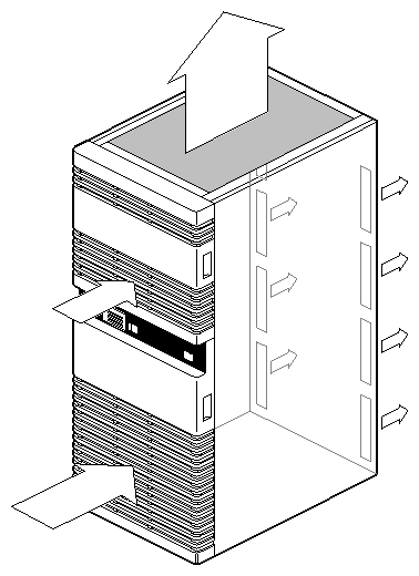
Check that the site provides proper air circulation. Figure 3-8 shows the airflow path of the chassis.
| Note: Be sure to allow sufficient space behind the chassis to facilitate future installation, cabling, and service activities. |
Check the floor-load rating of the site with the values listed in Table 3-5. Some site floor-load ratings are as low as 100 lb/ft2. To ensure that the flooring is adequate for all future chassis upgrades, you must make sure the floor-load rating meets 111 lb/ft2.
| Note: For Vaults sharing floor space with a Rackmount chassis, the floor-load rating must meet 133 lb/ft2. |
Table 3-5. Vault Floor-load Requirements
Weight | Floor-load Rating (lb/ft.2) | |
|---|---|---|
Typical | 650 lbs (295 kg) | 72 lb/ft2 (288.8 kg/m2) |
Maximum | 1,000 lbs (454 kg) | 111 lb/ft2 (444.3 kg/m2) |
For installations on raised floors, check that the construction will properly support the weight distribution. The Vault chassis uses four casters and four stabilizing levelers that distribute the weight load to the site floor. See Figure 3-9 for the caster and leveler locations. If a floor is modified, such as by cutting new access panels in computer floor tiles, determine if additional reinforcement is required.
Table 3-6 summarizes the physical requirements of the Vault chassis.
Table 3-6. Vault Physical Specifications
Parameter | Characteristic |
|---|---|
Dimensions, chassis |
|
62.3" (159 cm) | |
27" (69 cm) | |
48" (122 cm) | |
Dimensions, shipping |
|
height | 74.5" (189 cm) |
width | 46" (117 cm) |
depth | 59.5" (151 cm) |
| |
650 lbs (295 kg) | |
1,000 lbs (454 kg) | |
1,390 lbs (590 kg) |
This section defines the space required for these local devices provided with graphics systems:
monitor
keyboard and mouse
| Note: Server systems do not support graphics devices. All interaction is performed through an ASCII terminal. |
Provide the space shown in Figure 3-10 for a 19" or 21" monitor.
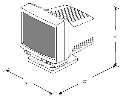
The monitor location must be within cabling distance of the main chassis, which is 30 feet for the standard monitor cable. See Chapter 5 for additional information on cables.
If several monitors are positioned in one location, maintain a minimum distance of three feet between monitors to eliminate visual artifacts on the monitor screens caused by electromagnetic interference (EMI).
Allow sufficient space to connect cables to the monitor, particularly when using a cable with 13W3 connectors and EMI filters. To reduce the possibility of signal reflection in a monitor cable, keep all bends in the cable to less than 90° when connecting the cable to a monitor. If a cable must be bent at 90°, keep the inside radius of the bend to a minimum of 3 inches. This guideline also applies when connecting a monitor cable to a chassis.
| Note: Check local regulations to ensure that the site complies with ergonomic and related codes. |
Table 3-7 summarizes the monitor physical requirements.
Table 3-7. Monitor Physical Specifications
Parameter | Characteristic |
|
|---|---|---|
| ||
Height | 18.4" (46.7 cm) | 18.4" (46.7 cm) |
Width | 19.2" (48.8 cm) | 19.7" (50 cm) |
Depth | 21" (53.4 cm) | 21.4" (54.3 cm) |
Weight | 99 lbs (45 kg) | 83 lbs (38 kg) |
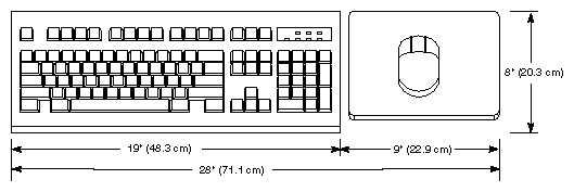
For graphics systems with a keyboard, provide desk or tray space within cabling distance of the system chassis (30 feet for the standard keyboard cable) and comfortable viewing distance of the related monitor. See Chapter 5 for additional information on cables.
A mouse connects directly to the keyboard. See Figure 3-11 for the dimensions of a typical keyboard and mouse layout.
Check your site for these environmental factors:
air conditioning
electrical interference (EMI, ESD)
vibration
acoustics
safety
Each site must provide proper air temperature, humidity, and filtration. Use Table 3-8, Table 3-9, and Table 3-10 to prepare the site air conditioning.
| Note: Temperature ranges apply to systems inside a building and out of direct sunlight. For installations at or above 8,000 feet, the system fans must be set on high-speed during operation. |
Table 3-8. Deskside Environmental Specifications
Parameter | Characteristic |
|---|---|
| |
operating | 5° to 35° C at sea level |
nonoperating | –20° to 60° C at sea level |
Heat dissipation (maximum configurations) |
|
8,100 Btu/hour (.68-ton AC load) | |
512 Btu/hour (.042-ton AC load) | |
| |
operating | 10 to 80%, noncondensing |
nonoperating | 10 to 95%, noncondensing |
| |
operating | 10,000 feet MSL, maximum |
nonoperating | 40,000 feet MSL, maximum |
| Note: MSL indicates mean (average) sea level or 29.92" (76 cm) of mercury barometric pressure. |
Table 3-9. Rackmount Environmental Specifications
Parameter | Characteristic |
|---|---|
Air temperature range |
|
operating | 5° to 35° C at sea level |
nonoperating | –20° to 60° C at sea level |
Heat dissipation (maximum configurations) |
|
server and graphics chassis, 220V 1-phase | 16,000 Btu/hour (1.3-ton AC load) |
server and graphics chassis, 220V 3-phase | 24,000 Btu/hour (2-ton AC load) |
Humidity range |
|
operating | 10 to 80%, noncondensing |
nonoperating | 10 to 95%, noncondensing |
Altitude |
|
operating | 10,000 feet MSL, maximum |
nonoperating | 40,000 feet MSL, maximum |
| Note: MSL indicates mean (average) sea level or 29.92" (76 cm) of mercury barometric pressure. |
Table 3-10. Vault Environmental Specifications
Parameter | Characteristic |
|---|---|
Air temperature range |
|
operating | 5° to 35° C at sea level 5° to 30° C above 5,000 feet |
nonoperating | –20° to 60° C at sea level |
Heat dissipation (maximum configuration) | 12,000 Btu/hour (1-ton AC load) |
Humidity range |
|
operating | 10 to 80%, noncondensing |
nonoperating | 10 to 95%, noncondensing |
Altitude |
|
operating | 10,000 feet MSL, maximum |
nonoperating | 40,000 feet MSL, maximum |
| Note: MSL indicates mean (average) sea level or 29.92" (76 cm) of mercury barometric pressure. |
Two primary sources of problems for computer systems are electromagnetic interference (EMI) and electrostatic discharge (ESD).
EMI is caused by malfunctioning, incorrectly manufactured, or incorrectly installed devices that radiate electrical signals. Common sources of EMI include electronic, telephone, and communications equipment. EMI transmission can be either conducted or emitted.
Use properly shielded connectors and cables throughout the site to prevent the new system from generating EMI.
Challenge/Onyx systems meet the EMI ratings for FCC Class A; VDE Level A;
DOC Class A; VCCI Class 1; and CISPR-22, Class 1.
 | Caution: Failure to use shielded cables with the system violates FCC regulations and voids the manufacturer's warranty. |
Silicon Graphics designs and tests its products to be resistant to the effects of ESD. ESD can cause problems ranging from data errors and lockups to permanent component damage. To protect the systems from electrostatic discharge (ESD), use these precautions:
Minimize the use of carpeting at computer locations.
Verify that all electronic devices are properly grounded.
Keep all doors and access panels closed during computer operation.
Keep all screws, slide locks, and thumbnails fastened securely.
Use a static strap whenever working with the chassis or components.
Use antistatic packing material for storage and transportation.
Clear the site of all devices that create static electricity or possible sources of EMI.
The Challenge/Onyx product line is designed for the typical office and computing environment, requiring no special modifications or protection. If a system is installed at an industrial site, check that vibrations are kept within the limits shown in Table 3-11 for the entire product line.
Table 3-11. Challenge/Onyx Vibration Limits
Description | Value |
|---|---|
Less than 5-10 Hz at 0.01" total excursion, 10-500 Hz at 0.1 g | |
Less than 5-10 Hz at 0.02" total excursion, 10-500 Hz at 0.1 g | |
8-33 Hz, depending on configuration |
Check that the additional computer equipment acoustics (noise-emission levels) are within the limits for the particular site. See Table 3-12.
Table 3-12. Challenge/Onyx Acoustic Levels
Parameter | Level |
|---|---|
| |
typical | 57 dB |
maximum | 65 dB |
| |
typical | 60 dB |
maximum | 66 dB |
| |
maximum | 65 dB |
| Note: Check local codes to ensure that the site is compliant with worker safety regulations, such as those provided by UL, TUV, and CSA. |
The systems are designed for office environments such as large offices, shared work areas, and computer rooms. The measurements in this section are only guidelines because acoustics depend on many factors outside the control of the manufacturer. Room characteristics such as carpeting and wall coverings affect the noise levels at an installation.
If a site exceeds desirable noise levels:
Reduce the amount of flat reflective surfaces such as glass, tile, or metal.
Add sound-absorbing carpet, wall coverings, and drapes.
Add sound baffles in critical locations and be careful not to block airflow.
Install ceiling tiles with sound-absorbing properties.
Modify office space to isolate operators and hardware.
Check the site to ensure that it meets these safety considerations:
| Note: Check local code for additional safety factors affecting the site. |
Table 3-13 lists the safety organizations that approve these systems.
Table 3-13. Safety Agency Approval List
Safety Agency | Approval |
|---|---|
Listed under 1950 Information Technology Equipment | |
Certified under CSA 22.2 No. 950-M89—Information Technology Equipment | |
Licensed under CENELEC European Norm EN 60 950/06.88 |
| Caution: All plenum cabling (through ceilings and walls) must meet local codes for fire safety. Plenum cabling should be provided by the user. |
Verify that the selected physical location does not interfere with:
routine operations, such as loading media and attaching cables
normal traffic through aisles, hallways, or entrances
future expansion plans
Also, evaluate the site to ensure that the equipment is protected from potential flooding and other exposure to water, particularly in underground installations or sites at low elevation.
For work areas near the computer equipment, check that the ergonomic considerations of personnel are met, particularly air quality, temperature, and sound.