This chapter describes the power requirements for the Challenge, Onyx, and Vault product configurations and shows you how to prepare the site power for a system by:
determining the power requirements of the ordered system
installing power circuits
installing safety and protection equipment
 | Warning: A licensed electrician should inspect and/or perform all wiring to ensure that the installation meets local and country electrical codes. |
This section introduces and defines the power requirements for Challenge/Onyx products.
The Challenge/Onyx product line uses a modular, distributed power system to support a wide variety of chassis configurations. The power system uses off-line switchers (OLSs) to convert power input from AC to DC and distribute power inside a chassis. DC regulators installed on the CPU, memory, and IO4 boards step down the backplane voltage for use by those boards. Additional power boards supply the DC voltages required by the Challenge/Onyx and VME buses. This arrangement allows board-level voltage to be generated for populated cardcage slots only. See Table 4-1 to determine the number of OLSs used for each chassis configuration.
Use Table 4-1 to determine the power requirements for each type of chassis. If you have multiple systems, each chassis must be separately plugged into its own circuit with circuit breaker protection.
Table 4-1. Challenge/Onyx System Power Requirements
Description | Country | Power VAC input |
|
| Hertz |
| Phase | Rating | Power Supply |
|
|---|---|---|---|---|---|---|---|---|---|---|
|
| nom | min | max | min | max |
| amps | watts | qty |
Deskside 110VAC Nom | US/Japan | 110 | 100 | 132 | 50 | 60 | 1 | 16 | 1500 | 1 |
Deskside 95VAC Nom | Japan | 90 | 85 | 132 | 50 | 60 | 1 | 16 | 1200 | 1 |
Deskside 220VAC | US/Int'l | 220 | 187 | 264 | 50 | 60 | 1 | 13 | 1900 | 1 |
Rackmount 220VAC 1P | US/Int'l | 208 | 187 | 264 | 50 | 60 | 1 | 24 | 3800 | 2 |
Rackmount 220VAC 3P | US | 208 | 187 | 264 | 50 | 60 | 3 | 24 | 5700 | 3 |
Rackmount 220VAC 3P | Int'l | 400 | 360 | 480 | 50 | 60 | 3 | 24 | 5700 | 3 |
Vault 220VAC | US | 208 | 187 | 264 | 50 | 60 | 1 | 12 | 2600 | up to 7 |
Vault 220VAC | Int'l | 208 | 187 | 264 | 50 | 60 | 1 | 12 | 2600 | up to 7 |
A deskside server system always uses 110VAC wiring (except in Japan, where it is 95VAC). For a deskside graphics chassis, determine the number of devices in the existing configuration and add any planned future devices. If the total exceeds the number of devices shown in Table 4-2, install 220VAC wiring. It is much easier to install ample power during initial preparation than to upgrade power later when wiring is already in place and a site is in operation. If a chassis is unlikely to exceed the quantities shown in Table 4-2, install 110VAC wiring.
Table 4-2. Maximum Configurations for a 110VAC, 1500-watt Deskside Chassis
Device Name | |
|---|---|
RM board | 2 |
CPU board, 4 R4400 each | 2 |
Disk | 7 |
VME board | 3 |
For a rackmount chassis, determine if the chassis will have a third cardcage added when this option is available. For chassis requiring the third cardcage, prepare the circuit so that it is easily changed to 3-phase when required. Preparing the circuit in advance is much easier than upgrading power later when wiring is already in place and the site is in operation. If there are no plans to include a third cardcage in the chassis, wire the circuit for 220VAC 1-phase power.
Table 4-3 provides KVA (kilo voltamps) and KBTU (kilo British thermal units) ratings for the Challenge/Onyx deskside and rackmount systems. These values help to determine the type of uninterruptible power supply (UPS) to purchase for these systems.
Table 4-3. KVA and KBTU Ratings
Chassis | KVA | KBTU |
|---|---|---|
All Challenge/Onyx L (Deskside) systems | 2.4 | 8.16 |
All Challenge/Onyx XL (Rackmount) systems | 7.2 | 24.5 |
 | Note: The KVA factor is determined by dividing the output of the power supply/supplies by its efficiency ratings. For example, an OLS with a power output of 1900 watts and an efficiency rating of 80 percent, has a VA value of about 2400 (rounded off to the nearest hundred) or a KVA value of 2.4. The KBTU rating is determined by multiplying the KVA value by 3.4. The values in Table 4-3 are based on systems containing all the possible options. |
This section shows you how to install a power circuit by performing these tasks:
reviewing the site's physical requirements
wiring the main branch circuit
wiring the chassis branch circuits
In addition, Section 4.2.4 identifies the various power cables and connectors, and Section 4.2.5 diagrams the chassis internal wiring for all power configurations.
Ensure that power outlets are within the maximum cabling distance of the chassis and monitors. Monitors require a wall outlet since the chassis do not provide any peripheral power outlets. The typical cable length is 10 feet. See Table 4-6 and Table 4-7 through Table 4-15 for more details on cables.
Maximum cable lengths are based on the wire gauge of the standard power cables. Consult with a licensed electrician to determine the wire gauge for custom cables.
Make sure that power cables are properly routed and guarded, particularly in areas frequented by personnel. Check the cabling plans to verify that sufficient length is allowed for proper slack through all routing, especially for indirect routing that runs cables along walls or in ceiling racks.
If an existing main power circuit is selected for the new computer equipment, check the circuit for any electrical noise-generating equipment, such as motors, calculators, and typewriters, and transfer these devices to a circuit other than ones servicing computer equipment.
Evaluate the quality of the power supplied by the local power company. Reliable computer operation requires power that is mostly free of fluctuations, transients, surges and spikes, and noise. If the local power quality is questionable, line conditioning equipment may be required.
Install a main branch circuit panel with properly rated circuit breakers for each branch circuit in the panel. Consider adding an emergency power shutdown control to this main panel, as discussed in Section 4.3.2, "Emergency Power Shutdown Control."Figure 4-1 shows the wiring for a main branch circuit panel.
| Warning: A licensed electrician should inspect and/or perform all wiring to ensure that the installation meets local and country electrical codes. |
 | Caution: For connection to IT power systems, a four-pole breaker must be provided at the building site. |
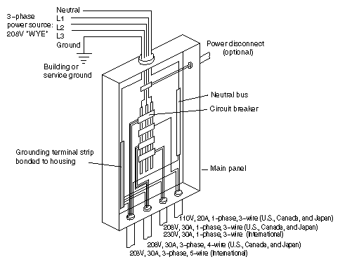
Provide a separate power circuit for each chassis. Wire the circuits using the diagrams and tables in this section for the deskside and rackmount chassis.
Table 4-4 provides power wiring configurations for the deskside systems.
| Note: The Onyx L, 20-span configuration, requires 220VAC power. |
Table 4-4. CHALLENGE L and Onyx L (Deskside Systems) Power Configurations
System Type | U.S./Canada/Japan Wiring Configuration | International Wiring Configuration |
|---|---|---|
CHALLENGE L | See | See |
Onyx L (10-span) | Phase to neutral (115VAC) See | Phase to neutral (230VAC) See |
Onyx L (20-span) | See | Phase to neutral (230VAC) See |
Table 4-5 provides power wiring configurations for the rackmount systems.
Table 4-5. CHALLENGE XL and Onyx XL (Rackmount Systems) Power Configurations
System Type | U.S. /Canada/Japan Wiring Configuration | International Wiring Configuration |
|---|---|---|
| See | See | |
| See | See |
The power supplies in Challenge/Onyx systems include advanced power factor correction circuitry. Therefore, the power source lines are affected by the power load of the chassis as a 99 percent pure resistive load. The power supplies also provide 3-phase power balance between phases within +/- 10 percent maximum by specification, and +/- 2 percent nominal.
"Three-phase" typically refers to the phase-to-phase voltage, which in many international countries is called 400VAC 3-phase. Since Challenge/Onyx systems are connected to an international power source using the "WYE" method, the chassis power supplies use the 230VAC phase-to-neutral voltage and not the 400VAC phase-to-phase voltage. Internal to a Challenge/Onyx rackmount chassis, voltage is always 187 to 264VAC.
The branch circuit wiring should be provided with an insulated grounding conductor that is identical in size, insulation material, and thickness to the earthed and unearthed branch-circuit supply conductors. (The grounding conductor should be green, with or without one or more yellow stripes.) This grounding or earthing conductor should be connected to earth at the service equipment or, if supplied by a separately derived system, at the supply transformer or motor-generator set.
The attachment-plug receptacles in the vicinity of the unit or system should all be of an earthing type, and the grounding or earthing conductors serving these receptacles should be connected to earth at the service equipment.
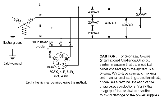
See Figure 4-2 through Figure 4-8 to determine the proper wiring for various types of chassis branch circuits.
Figure 4-2. Branch Circuit Diagram for 120VAC, 3-wire, 1-phase, U.S., Canada, and Japan (CHALLENGE L and Onyx L/10-span Deskside Systems)
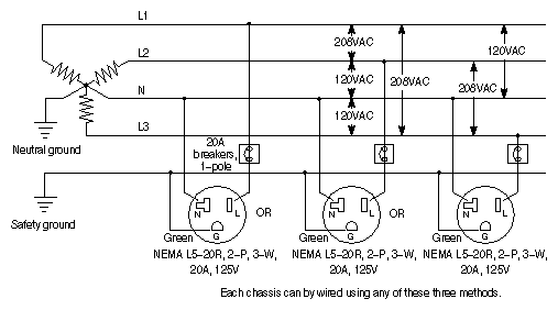 |
Figure 4-3. Branch Circuit Diagram for 208VAC, 3-wire, 1-phase, U.S., Canada, and Japan (Onyx L/20-span Deskside Systems)
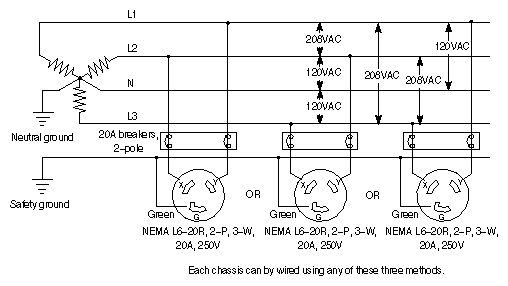 |
Figure 4-4. Branch Circuit Diagram for 230VAC, 3-wire, 1-phase, International (Onyx L/20-span Deskside Systems)
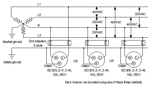 |
Figure 4-5. Branch Circuit Diagram for 208VAC, 3-wire, 1-phase, U.S., Canada, and Japan (CHALLENGE XL and Onyx XL Rackmount Systems—No Third Card Cage)
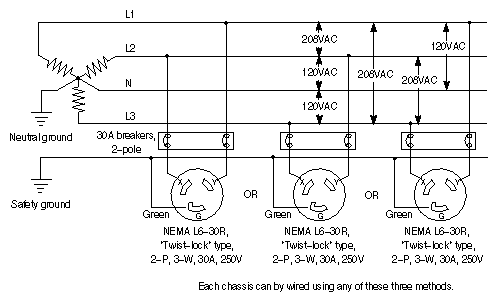 |
Figure 4-6. Branch Circuit Diagram for 230VAC, 3-wire, 1-phase, International (CHALLENGE XL and Onyx XL Rackmount Systems—No Third Card Cage)
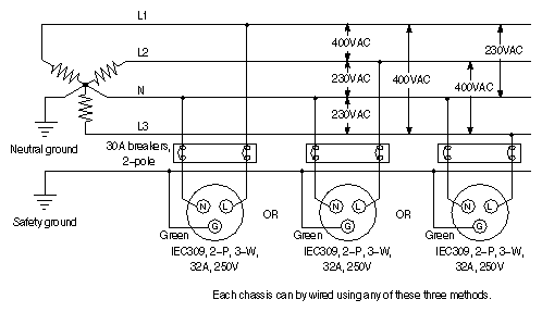 |
Figure 4-7. Branch Circuit Diagram for 230VAC, 4-wire, 3-phase, U.S., Canada, and Japan (CHALLENGE /Onyx XL Rackmount Systems—with Third Card Cage)
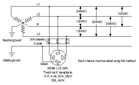 |
Figure 4-8. Branch Circuit Diagram for 400VAC, 5-wire, 3-phase, WYE-connected, International (CHALLENGE/Onyx XL Rackmount Systems—with Third Card Cage)
 |
This subsection provides additional power guidelines for 1- and 3-phase use.
On a 3-phase power distribution system, each phase is 120 degrees out of phase, and the following formula applies:
VAC phase-to-phase = VAC phase-to-neutral multiplied by 1.732
If you are connecting from 1-phase to another single-phase, this setup is still referred to as 1-phase (or single-phase) connection in the power industry.
If you are connecting equipment to all three phases, this setup is referred to as a 3-phase connection.
Table 4-6 summarizes the power cables and connectors for each power configuration, and Table 4-7 through Table 4-15 shows the physical appearance of each standard cable.
Table 4-6. Challenge/Onyx System Power Cable and Connector Specifications
Description | Cable Connector at Chassis End | Cable Connector at Power Source End | Cable Type | Power Source Connector |
|---|---|---|---|---|
Deskside 110VAC Nom | UL/CSA | |||
Deskside 95VAC Nom | IEC320-C19 | NEMA 5-20P | UL/CSA | NEMA 5-20R |
Deskside 220VAC |
|
|
|
|
U.S., Canada, and Japan | IEC320-C19 | UL/CSA | NEMA 6-20R | |
International | IEC320 C19 | IEC309, 2-P, 3-W, 16A, 240V | HAR | IEC309, 16A/240V, 2P + Ground |
Rackmount 220VAC 1P |
|
|
|
|
U.S., Canada, and Japan | NEMA L6-30P, 2-P, 3-W, 30A, 250V | UL/CSA | NEMA L6-30R | |
International | NEMA L6-30R | IEC309, 2-P, 3-W, 32A, 240V | HAR | IEC309, 32A/240VAC, 2P + Ground |
Rackmount 220VAC 3P |
|
|
|
|
U.S., Canada, and Japan | Fixed | NEMA L15-30P, 3-P, 4-W, 30A, 250V | UL/CSA | |
International | Fixed | IEC309, 4-P, 5-W, 32A, 415V | HAR | IEC309, 32A/380 to 415VAC, 3P + N + Ground |
Vault 220VAC |
|
|
|
|
U.S., Canada, and Japan | Fixed | NEMA L6-30P, 2-P, 3-W, 30A, 250V | UL/CSA | NEMA L6-30R |
International | Fixed | IEC309, 2-P, 3-W, 32A, 240V | HAR | IEC309 32A/240VAC, 2P + Ground |
Table 4-7. Deskside Power Cable, 110VAC, U.S., Canada, and Japan
Part Number | Description |
|---|---|
9350050 | Deskside power cable, 110VAC, U.S., Canada, and Japan: round UL/CSA cable, 10' length; NEMA 5-20P plug at source end, IEC320-C19 receptacle at chassis end. See Figure 4-9. |
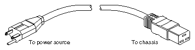
Table 4-8. Deskside Power Cable, 220VAC, U.S., Canada, and Japan
Part Number | Description |
|---|---|
9350051 | Deskside power cable, 220VAC, U.S., Canada, and Japan: round UL/CSA cable, 10' length; NEMA 6-20P plug at source end, IEC320-C19 receptacle at chassis end. See Figure 4-10. |
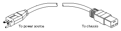
Table 4-9. Deskside Power Cable, 220VAC, International
Part Number | Description |
|---|---|
9350054 | Deskside power cable, 220VAC, international: round HAR cable, 10' length; IEC309, 2-P, 3-W, 16A, 240V plug at source end, IEC320-C19 receptacle at chassis end. See Figure 4-11. |
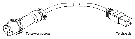
Table 4-10. Rackmount Power Cable, 220VAC, 1-phase, U.S.
Part Number | Description |
|---|---|
018-0180-003 | Rackmount power cable, 220VAC, 1-phase, U.S.: round UL/CSA cable, 10' length, NEMA L6-30P, 2-P, 3-W, 30A, 250V plug at source end, NEMA L6-30R receptacle at chassis end. NOTE: This cable plugs into a twist-lock 30A, 250V branch circuit receptacle such as a Hubbel receptacle, part number 2620-A (non-isolated ground) or IG-2620-A (isolated ground). See Figure 4-12. |
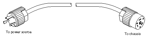
Table 4-11. Rackmount Power Cable, 220VAC, 1-phase, International
Part Number | Description |
|---|---|
018-0341-001 | Rackmount power cable, 220VAC, 1-phase, international: round HAR cable, 10' length, IEC309, 2-P, 3-W, 32A, 240V plug at source end, NEMA L6-30R receptacle at chassis end. See Figure 4-13. |
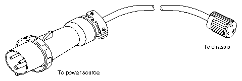
Table 4-12. Rackmount Power Cable, 220VAC, 3-phase, U.S.
Part Number | Description |
|---|---|
018-0350-003 | Rackmount power cable, 220VAC, 3-phase, U.S.: round UL/CSA cable, 10' length, NEMA L15-30P, 3-P, 4-W, 30A, 250V plug at source end, fixed cord at chassis end. NOTE: This cable plugs into a twist-lock 30A, 3-phase, 250V branch circuit receptacle such as a Hubbel receptacle, part number 2720-A (non-isolated ground) or IG-2720-A (isolated ground). See Figure 4-14. |
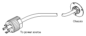
Table 4-13. Rackmount Power Cable, 400VAC, 3-phase, International
Part Number | Description |
|---|---|
018-0351-001 | Rackmount power cable, 400VAC, 3-phase, international: round HAR cable, 10' length; IEC309, 4-P, 5-W, 32A, 415V plug at source end, fixed cord at chassis end. See Figure 4-15. |
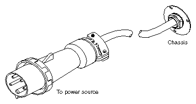
Table 4-14. Vault Power Cable, 220VAC, 1-phase, U.S.
Part Number | Description |
|---|---|
018-0280-002 | Vault power cable, 220VAC, 1-phase, U.S.: round UL/CSA cable, 10' length; NEMA L6-30P, 2-P, 3-W, 30A, 250V plug at source end, fixed cord at chassis end. See Figure 4-16. |
Table 4-15. Vault Power Cable, 220VAC, 1-phase, International
Part Number | Description |
|---|---|
018-0276-001 | Vault power cable, 220VAC, 1-phase, international: round HAR cable, 10' length; IEC309, 2-P, 3-W, 32A, 240V plug at source end, fixed cord at chassis end. See Figure 4-17. |
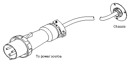
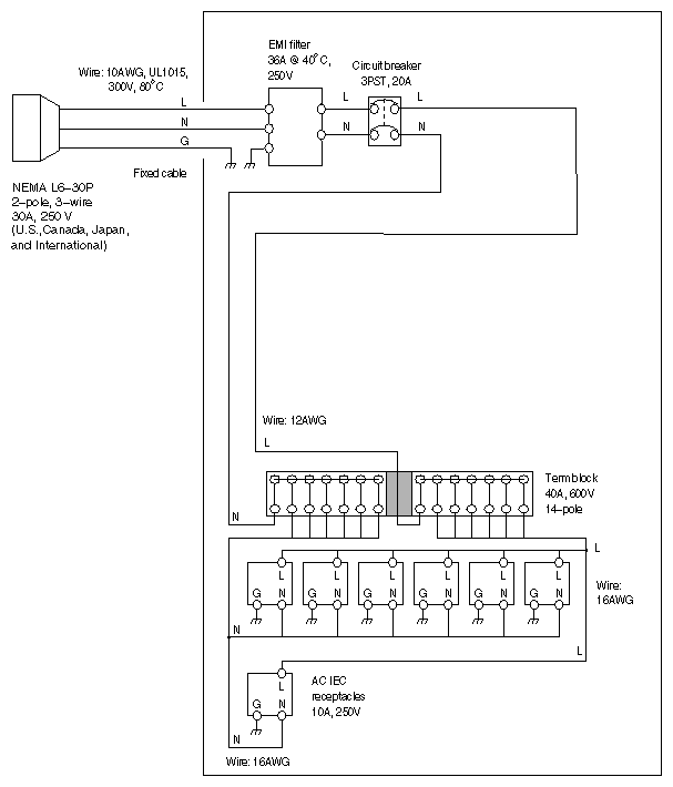
This section provides wiring diagrams for Challenge/Onyx internal power circuits.
Figure 4-18 provides a deskside chassis wiring diagram for 110VAC and 220VAC, 3-wire, 1-phase power circuits.
| Note: The power supply uses auto-switching to convert either 110VAC or 220VAC to the levels required by the chassis. No manual configuration of the power supply is required. |
| Warning: A deskside graphics system can exceed the capabilities of 110VAC wiring when the chassis is upgraded to various configurations. Always check the configuration requirements of an upgraded chassis and modify site power to 220VAC as required. |
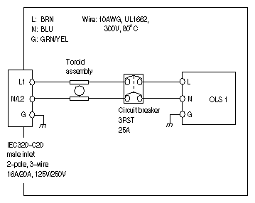
Figure 4-19 provides a rackmount chassis wiring diagram for 220VAC, 3-wire, 1-phase power circuits.
Figure 4-19. Rackmount Chassis Wiring Diagram for 220VAC, 3-wire, 1-phase Power (U.S., Canada, and Japan)
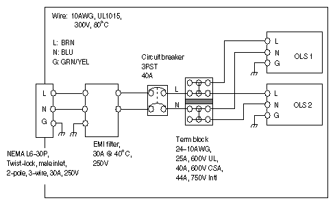 |
Figure 4-20 provides a rackmount chassis wiring diagram for 220VAC, 4-wire, 3-phase power circuits.
Figure 4-20. Rackmount Chassis Wiring Diagram for 220VAC, 4-wire, 3-phase Power (U.S., Canada, and Japan)
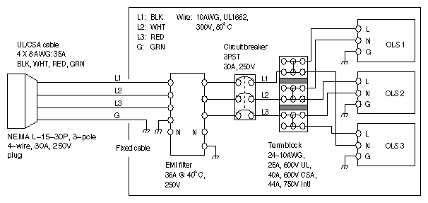 |
Figure 4-21 provides a rackmount chassis wiring diagram for 400VAC, 5-wire, 3-phase power circuits.
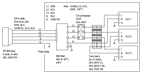
Figure 4-22 provides a vault chassis wiring diagram for 220VAC, 3-wire, 1-phase power circuits.
Depending on the location and size of an installation site, consider the following for safety and protection:
Cable management equipment protects personnel from electrical accidents and equipment from premature wear and accidental loss of power. Cable management equipment includes cable routing guides and trays, walkway guards, and plug restraints.
Install cable management equipment if:
people require access to locations with power cables or connections
power cables could become disconnected
power cables pass across aisles or other paths
Always isolate power cables from signal cables to minimize the transmission of noise from the power to the signal cables.
| Warning: Check the cable management equipment specifications for power cable limitations. Improperly installed cable management equipment can cause unsafe working conditions. |
An emergency power shutdown control is a safety feature that protects personnel and equipment from these hazardous electrical situations:
personnel are exposed to or in contact with electrical sources
large installations have many components to power off quickly during emergencies
site is subject to power outages, drop-outs, and surges
Install an emergency power shutdown control at the main entries to the computer location. For large installations, place an additional control within easy reach of the main administrator's station. The control must be wired to the main branch circuit panel to disconnect power to all computer equipment at the location.
| Warning: A licensed electrician should inspect and/or perform all wiring to ensure that the installation meets local and country electrical codes. |
Check the site for adequate fire fighting equipment for the new computer devices. Place an adequate number of small fire extinguishers (rated for electrical fires) at entrances, exits, and other obvious locations. Bear in mind that some fire extinguishing equipment leaves no residue, while other equipment can destroy sensitive components and surfaces.
For larger installations involving several system chassis, consider isolating all computers in one room and providing room-level fire protection.
| Warning: Use licensed professionals to install extensive fire protection systems. Room-level fire protection typically relies on gas evacuation within an enclosed area. In addition, adequate warnings, overrides, and training must be provided to ensure personnel safety. |
Install lightning protection at the site if:
the site is in an electrical storm area
the local utility company uses lightning protection on the primary power source
an overhead power service provides the site's primary power
Lightning protection also helps prevent damage at locations with large power surges, such as in some industrial settings and at locations with older or overburdened power grids.
Consult with a licensed professional or appropriate organization for assistance with lightning protection systems within the site's area.
For more information on protecting people and equipment from lightning hazards within the U.S., obtain a copy of The National Fire Protection Association's Lightning Protection Code (NFPA Standard 78).
Power-line treatment may be required if the site uses unreliable power, with problems such as fluctuating voltage, transients, surges and spikes, and noise. Common causes of unreliable power are old wiring, load-switching equipment, such as welding and plating devices, and variable-speed motors or motors that start and stop frequently.
A variety of devices are available to improve the quality of a power line, including:
line conditioners
line regulators
isolation transformers
uninterruptible power supplies (UPS)
Note: See Section 4.1.3, "KVA and KBTU Ratings," for information on determining the type of UPS to use for a system.
Consult with a licensed professional or an appropriate organization for assistance with selecting and installing power-line treatment equipment.
For more information on power treatment within the U.S., contact these organizations:
The National Technical Information Service, U.S. Department of Commerce, Springfield, VA 22161
The Institute of Electrical and Electronics Engineers, Inc., 345 East 47th Street, New York, NY 10022
The American National Standards Institute, 1430 Broadway, New York, NY 10018