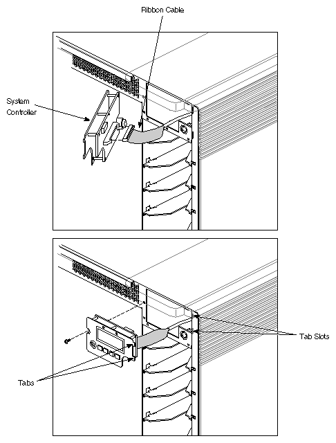
To replace the status panel (P/N 041-0025-xxx), perform the following:
Power down the system, as described in Section 5.16.2.
Open the front door, as described in Section 5.16.3.
Remove the screw from the left side of the system controller.
Pull the left side of the system controller out until the two tabs on the right side of the controller are clear of their slots in the chassis. See Figure 5-79.
Carefully remove the status panel from its cavity in the chassis.
Disconnect the ribbon cable from its connector on the status panel.
Reverse these steps to install the status panel.
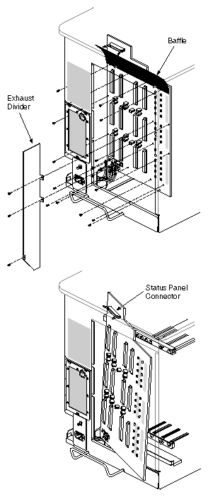
To remove the backplane, see Figure 5-80 and follow these steps.
 | Note: The backplane part number for a server system is 030-0314-xxx. The backplane part number for a graphics system is 030-0310-xxx. |
Power down the system, as described in Section 5.16.2.
Open the front door, as described in Section 5.16.3.
Open the I/O door, as described in Section 5.16.5.
Slide out all boards one-quarter of their length so that they are released from the backplane but still supported by the card guide shelves.
Remove the rear plastic panel and sheet-metal cover, as described in Section 5.16.7.
Remove the exhaust divider (P/N 040-0395-xxx) by removing three screws (see Figure 5-80). Two screws secure the middle of the divider to the backplane. The third screw can be found near the bottom of the chassis.
Lift the divider out of the chassis.
Remove the black plastic baffle by prying up the bottom with your fingers (see Figure 5-80). The bottom of the baffle mounts onto two metal pins near the top of the backplane. The baffle covers the status panel connector located near the top left-hand corner of the backplane.
Disconnect the cables that attach to the backplane:
8-volt connector wires (four total)
4-pin OLS controller cable
2-pin SCSI power cable
Note: Be sure to remove the black plastic baffle, as described in step 8. 4-pin blower power cable
RS-232 control cable
Remove the 14 screws holding the backplane to the chassis and card guide shelves.
Remove the backplane by sliding it off the four positioning tabs on the card guide shelves and angling the backplane to clear the chassis.
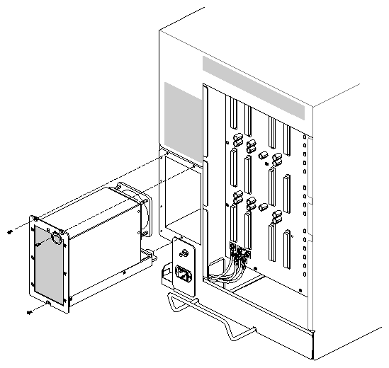
Use these procedures to replace the OLS (P/N 013-0513-xxx):
| Note: The OLS is an autoranging power supply that works for both 110 and 220 VAC operation. |
Power down the system, as described in Section 5.16.2.
Remove the rear plastic panel and sheet-metal cover, as described in Section 5.16.7.
Remove the three screws that hold the OLS to the chassis (see Figure 5-81).
Pull out the OLS using the ring (see Figure 5-81).
Note: You may need to wiggle the OLS slightly from side to side before you can pull it away.
| Note: The power connector assembly (P/N 013-0515-xxx) is used for both 110 and 220 VAC. |
Use these procedures to replace the power connector assembly:
Power down the system, as described in Section 5.16.2, and remove the power cord.
Remove the back plastic panel and sheet-metal cover, as described in Section 5.16.7.
Disconnect the AC hot, neutral, and earth ground wires from the power supply.
Remove the four screws that hold the power connector assembly to the chassis.
Remove the ground wire from the power to the chassis.
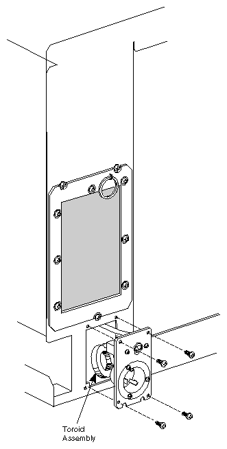
Remove the power connector assembly from the chassis (see Figure 5-82).
Reverse these steps to install a new power connector assembly.

Caution: Do not force fit the new power connector assembly. If it does not easily fit, readjust the toroid placement.
The Everest bus (Ebus) boards (IP19, MC3, and IO4) use 560-pin Futurebus+ Metral connectors that require some force to engage the pins and sockets. Use care when installing these boards because the connector pins can bend.
| Caution: Before installing a new board, check for ribbon cables to the immediate left of the slot receiving the new board. Disconnect or secure these cables before inserting the new board; otherwise, the cables of the adjacent board may be chafed and damaged by the pins of the new board. |
The components are extremely sensitive to electrostatic discharge. Use proper antistatic procedures when handling all components.
Power down the system, as described in Section 5.16.2.
Open the front door, as described in Section 5.16.3.
Open the I/O door, as described in Section 5.16.5.
Inspect the chassis connector pins and straighten any bent pins (if possible).
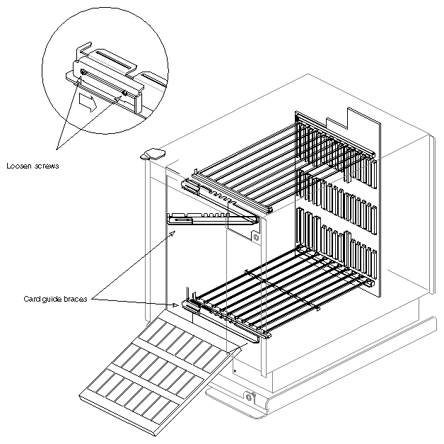
Remove the two board braces (013-0578-xxx) that secure the top and bottom of the system boards by loosening the Phillips screws and moving the slide bar to the right. You can then pull out the braces (see Figure 5-83).
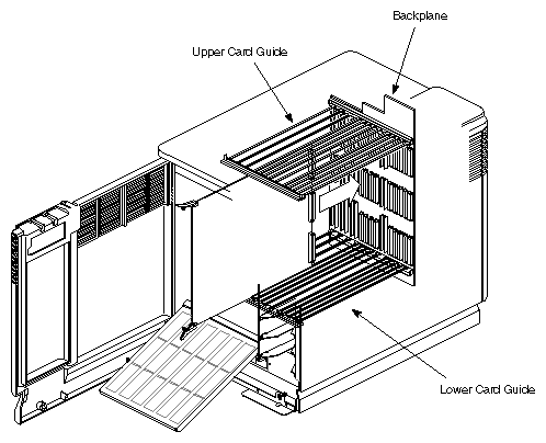
Note: If present, take out the bottom disk drive before removing the bottom brace. Place the new board in the card guides and slide the board halfway into the chassis (see Figure 5-84). The two rails running along the top and bottom of the chassis act as guides and secure the boards within the chassis.
Pull the upper and lower ejector tabs toward you until they line up lengthwise with the horizontal edges of the board.
Slide the board completely into the slot while angling the ejectors of the board so that the U-shaped grooves of the ejectors fit into the metal frames of the chassis.
Apply equal pressure on the upper and lower ejector tabs toward the center of the board's lower edge until both lips are vertical.
You should hear and feel the board snap into the board ejectors and backplane connectors. The board is now seated in the backplane.
This section provides basic instructions for replacing an option board but does not cover special requirements. To install a special option board, please refer to the installation instructions provided with the board.
| Caution: Before installing a new board, check for ribbon cables to the immediate left of the slot receiving the new board. Disconnect or secure these cables before inserting the new board; otherwise, the cables of the adjacent board may be chafed and damaged by the pins of the new board and observer proper ESD practices. |
The backplane adheres to a new practice that allows a VME option board to be installed without opening the rear of the chassis. When installing VME boards, use the left slot first and continue installing boards to the right without skipping any slots. This sequence is required because the backplane loops the signals from slot 5 to slots 1 through 4, and any open slot interrupts the signal flow to subsequent slots.
Follow these instructions to replace an option board:
Power down the system, as described in Section 5.16.2.
Open the front door, as described in Section 5.16.3.
Open the I/O door, as described in Section 5.16.5.
Remove the two board
braces (013-0578-xxx) that secure the top and bottom of the system boards by loosening the Phillips screw and moving the slide bar to the right. You can then pull out the braces (see Figure 5-83).
Note: If present, take out the bottom disk drive before removing the bottom brace. Grasp the option board by the two upper and lower ejector tabs (see Figure 5-84).
Place the new board in the card guides and slide the board halfway into the chassis. The two rails running along the top and bottom of the chassis act as guides and secure the boards within the chassis.
Pull the upper and lower ejector tabs toward you until they line up lengthwise with the horizontal edges of the board.
Slide the board completely into the slot while angling the plastic ejectors of the board so that the U-shaped grooves of the ejectors fit into the upper and lower metal frames of the chassis.
Push the upper and lower ejector tabs outward.
You should hear and feel the board snap into the board ejectors and backplane connectors. The board is now seated in the backplane.
Resecure the board lock bars across the top and bottom of the boards in the card cage.
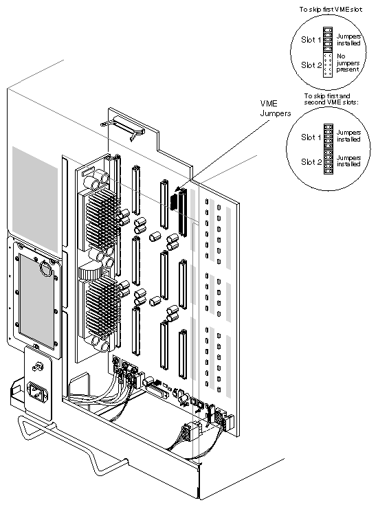
Skipping a slot is occasionally required to fit oversized VME boards or improve air flow. A slot can be skipped if jumper blocks are placed on the appropriate VME jumper block pins located on the rear of the backplane (see Figure 5-85).
| Note: If you install the VME boards in order (from left to right), then no jumpering is required. |
The general guideline is to insert jumpers into the jumper banks corresponding to the VME slot number that you are skipping. For example, if you are skipping the first VME slot, you need to insert jumpers into jumper bank 1. See the following additional examples:
If you are skipping the first VME slot (that is, slot 5 in an Onyx or slot 7 in a CHALLENGE system) to use the next VME slot, you must place five jumpers in the jumper bank, designated as slot 1 (see Figure 5-85).
If you are skipping the first two VME slot and wish to use the third VME slot, you must place jumpers in jumper banks 1 and 2.
If you wish to skip over VME slots, for example, from the first VME slot over to the third VME slot, you must place jumpers in bank 2.
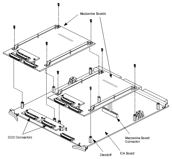
The optional SCSI and FDDI mezzanine boards attach to the IO4 baseboard through four standoffs. An IO4 board can house up to two mezzanine boards. Follow these procedures to install or remove a mezzanine board:
Orient the board so that the I/O channels face the same direction as the IO4 baseboard channels, then line the holes on each corner of the mezzanine board with the applicable standoffs (see Figure 5-86).
Press down on the mezzanine board so that the connector underneath engages the connector on the IO4 board.
Secure the mezzanine board to the IO4 baseboard using the truss-head screws.
Note: The mezzanine board may appear to fit very loosely on the IO4 baseboard. This is normal. The mezzanine boards are designed to float on the standoffs.
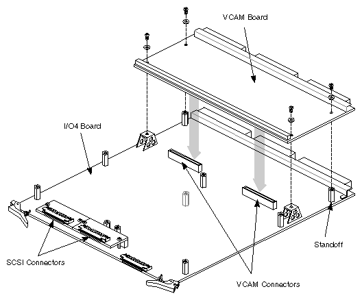
The VCAM (VME channel adapter module) board mounts on the rear of the IO4 baseboard and comes standard with every CHALLENGE or Onyx system. Follow these instructions to install or remove a VCAM board:
Orient the VCAM board so that the backplane connectors face the rear.
Line up the four holes on the board with the two standoffs and mounting braces (see Figure 5-87).
Push down evenly on the board so that the two connectors on the bottom of the VCAM board engage the two connectors on the IO4 baseboard.
Secure the VCAM board using four Phillips screws and washers.
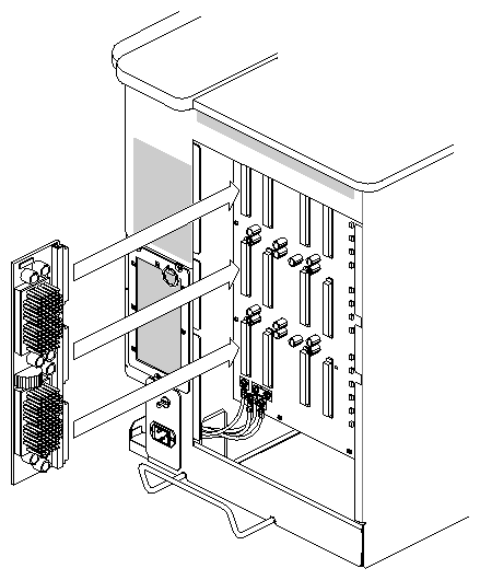
The power boards install directly onto the backplane. To remove or replace a power board, see Figure 5-88 and follow these steps:
Power down the system, as described in Section 5.16.2.
Remove the rear plastic panel and sheet-metal cover, as described in Section 5.16.7.
Grasp the applicable power board, then use two hands to pull the board straight out.
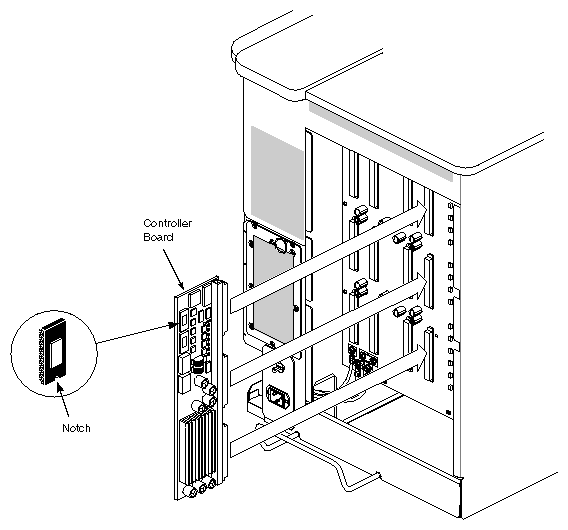
This section describes how to upgrade the PROM in the System Controller board in the CHALLENGE/Onyx system, if applicble. The System Controller board (also called the E-power board) is one of the power boards that plugs into the backplane (see Figure 5-89). This board contains the control logic for the status panel display and also supplies power for the Ebus.
This firmware upgrade corrects the following sporadic failures:
blower failure problems
serial communication problems associated with the UART
deskside chassis (CHALLENGE/Onyx L) start-up display errors
| Note: For a complete list of reporting error problems, see the associated software release notes. |
This upgrade applies to the following versions of the System Controller board:
030-0265-005 and below
030-0380-002 and below
| Note: Despite the two different part numbers, these boards are interchangeable in the field. The 030-0380-00x board is a slightly improved version of the 030-0265-xxx board. |
To remove the System Controller board, follow these instructions.
| Caution: Observe proper electrostatic discharge precautions when handling components: use an antistatic surface and wear a ground strap. |
Ensure that the system is backed up; then power down the system.
See Section 5.17.10, "Replacing a Power Board," to access the System Controller board.
Remove the System Controller board from its slot on the backplane.
Place the board on a soft, antistatic surface (such as an antistatic mat or foam padding).
| Note: The soft, compliant surface helps absorb the shock, preventing possible IC pin breakage when you install the PROM. |
See Figure 5-89 for the location of the PROM on the System Controller board.
Follow these instructions to install the new firmware:
| Caution: Observe proper electrostatic discharge precautions when handling components: use an antistatic surface and wear a ground strap. |
Locate the old PROM (see Figure 5-89), then use an IC puller to remove this PROM from its location.
Note the orientation of pin 1 in Figure 5-89, then install the new PROM
(P/N 070-1117-005) and be careful not to bend or break any pins.Attach the deviation authorization label to the System Controller PCB
(DA# 798).Install the updated System Controller board in its power board location.
The CHALLENGE/Onyx deskside system provides seven half-height drive bays or up to three full-height bays. See the Peripherals Reference Guide (Document Number 108-7027-xxx) for important information concerning system limits and drive configuration before continuing with this section.
| Caution: Disk drives can be damaged if they are removed while spinning. Wait until the system is powered down and the drive has halted before removing it from the system. |
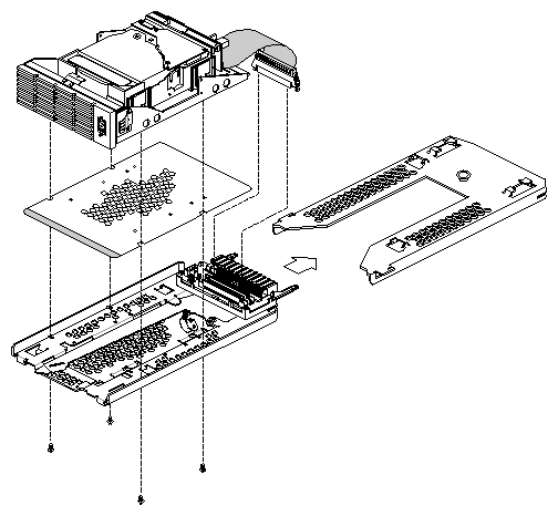
The CHALLENGE/Onyx deskside system does not use the previous front-loading drive mounts of earlier Silicon Graphic systems, such as the Single Tower or Crimson. The drives now sit on a drive sled that mounts on a drive shelf in the chassis (see Figure 5-90).
To install a SCSI drive on a drive sled
If the drive did not come already mounted to a sled, place it on top, as shown in Figure 5-90. Be sure the EMI shelf is affixed to the bottom of the drive and aligned, as shown in the drawing.
Secure the drive to the bottom of the sled with the four screws provided.
Plug the drive adapter cable into the proper channel connector.
Orient the drive and sled assembly so that the connectors on the back face away from you.
Note: The differential IBM drives may also need to be oriented so that the connectors are on the bottom half of the drive. Carefully insert the device into the drive until it seats firmly into the lever catch and the locking lever has moved all the way to the right.
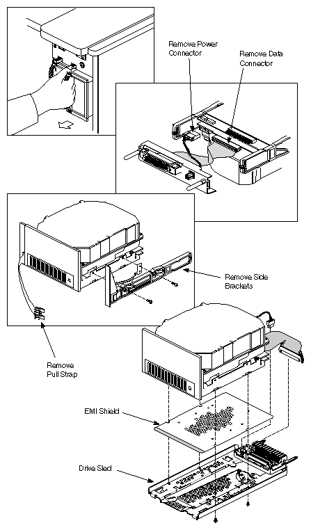
If you need to convert an existing old-style front-loading drive, see Figure 5-91 and follow these steps:
Place the drive to be converted on top of an antistatic surface.
Remove the side bracket on each side of the drive by removing four screws (total); see Figure 5-91.
Remove the old data connector and power connector to the drive and remove the metal bracket assembly in back of the drive.
Place the EMI shield on top of the drive sled assembly. Ensure that the cutouts align with the four mounting holes on the drive sled.
Place the drive on top of the EMI shield and drive assembly.
Secure the drive by attaching four screws underneath the drive sled.
Plug the data connector into the A or B channel on the drive sled.
Plug the power cable into the power connector on the drive sled (see Figure 5-91).
Ensure that the drive is mounted on a drive sled. See Section 5.17.12.1, "Installing a Drive on a Drive Sled," for more information.
To install a SCSI drive
Install the drive module into the drive tray and slide the module all the way into place, then push the drive lever down. The drive module should click into place, flush with the slot, and should not come out when you pull it.
Slide the drive lever to the right so that the hook engages the mounting stem.
Power down the system, as described in Section 5.16.2.
Open the front door, as described in Section 5.16.3.
Push the drive lever to the left. This disengages the hook from its mount.
Carefully slide the device and drive sled out of the slot.
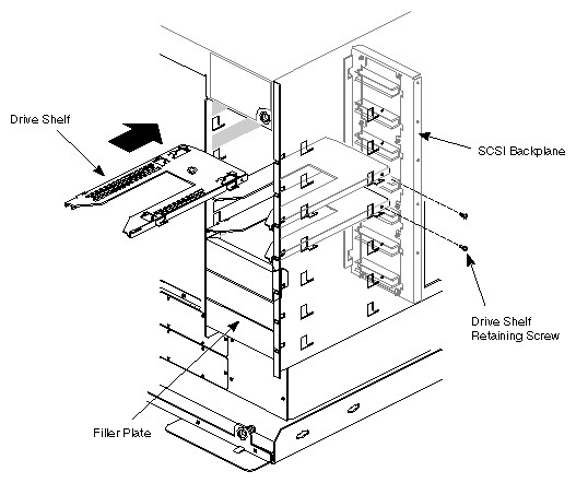
To convert a half-height slot to a full-height slot or vice versa, you must either remove or add a drive shelf.
To remove a drive shelf,
Power down the system, as described in Section 5.16.2.
Open the chassis front door, as described in Section 5.16.3.
Remove the appropriate drives, as described in Section 5.17.12.
Remove the right-side panel (the panel closest to the drives), as described in
Section 5.16.8.On the exposed sheet-metal, remove the screw holding the appropriate drive shelf in place. See Figure 5-92.
Grasp the back of the shelf firmly, then pull the drive shelf straight out.
Note: Owing to a friction-fit, you may have some difficulty in pulling the drive shelf out. Pull the drive shelf forward until the right side drops down in its chassis slots.
To install a drive shelf,
Position the drive shelf with the mounting knob up.
Align the cut-in grooves in the back of the shelf, with the rear tabs on each side of the drive walls. Position the grooves in the front of the shelf to mesh with cut-ins in the front of each side of the drive walls.
Push the drive shelf firmly into the chassis.
Secure the drive shelf with a screw to the right side of the chassis.
Reverse the steps 1 through 4 in the removal procedure to complete the installation.
Use these procedures to replace the drive bulkhead assembly (P/N 013-0510-xxx):
Power down the system, as described in Section 5.16.2.
Remove the front-loading drives, as described in Section 5.17.12.
Remove the rear panel, as described in Section 5.16.7.
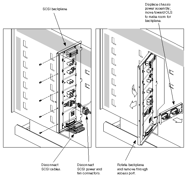
Remove the three screws that secure the OLS, as described in Section 5.17.3.
Pull the OLS out a few inches or so from the chassis so that you can remove the power connector to the SCSI backplane.
Next, remove the side panel (see Section 5.16.8).
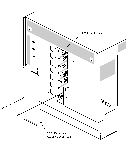
Remove the access cover plate over the bulkhead assembly by removing four screws from the sheet-metal housing on the right side of the chassis (see Figure 5-92). Lift the cover from the bottom and away from the chassis.
Caution: With the cover off, you can now see the bulkhead assembly. Before you start pulling out cables, note the SCSI cable connectors A and B on the bottom of the SCSI backplane (see Figure 5-92). Be sure to label these cables (SCSI A and SCSI B) to ease reinstallation. With the exposed bulkhead assembly, remove the SCSI A and B cables from their connectors on the bottom of the SCSI backplane. Be sure to label the SCSI cables to prevent miscabling during reinstallation
Remove the OLS power cable and the fan power cable from the back of the SCSI backplane (see Figure 5-92).
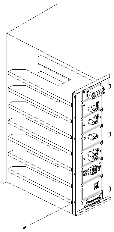
Remove the five screws that attach the drive bulkhead assembly to the center of the sheet-metal housing (see Figure 5-94).
Push the drive bulkhead assembly from the front of the SCSI backplane to the rear, then lift out the bulkhead from the chassis.
To install the drive bulkhead assembly,
| Note: Note the three tabs on the left side of the bulkhead assembly (see Figure 5-95). Be sure these tabs align with the slits located on the center wall of the chassis. |
Insert the drive bulkhead assembly with the alignment tabs going into the chassis first.
Reverse steps 1 through 11 of the removal procedure to install the drive bulkhead.
Note: When reinserting the side cover, install the top of the cover first into the outside sheet-metal housing. The top of the cover should mesh with the lip of the housing (see Figure 5-92).
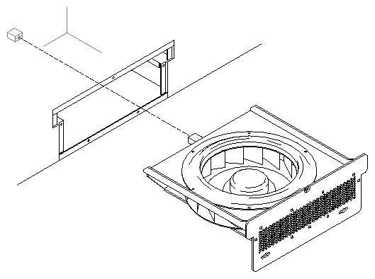
To remove the blower module (P/N 013-0500-xxx),
Power down the system, as described in Section 5.16.2.
Remove the left side panel (the side opposite the drives). See Section 5.16.8.
Maker sure that the fans have stopped spinning then remove the three screws that secure the blower module to the sheet-metal housing (see Figure 5-96).
Grasp the module and gently pull it out of the chassis.
To install the blower module, reverse steps 1 through 4.
| Note: Push the fan module all the way into the housing to ensure proper connection. |