This chapter provides an overview of the chassis for the CHALLENGE/Onyx deskside system; a description of the controls, connectors, and indicators; and a functional description of the backplane.
Table 2-1 identifies the new principal components of the CHALLENGE/Onyx deskside systems as well as available options and briefly compares them with previous Crimson and Single Tower technology.
Table 2-1. The New CHALLENGE/Onyx System Components
Product/Board Name | Description | Comments/Comparison |
|---|---|---|
System processor boards |
|
|
IP19 (P/N 030-0249-xxx, | This board replaces the IP17 single processor, 50 MHz R4000 CPU in the Crimson and Single Tower systems. Not only is the IP19 board significantly faster, but it contains from two to four R4400s per CPU board. Another significant difference between the IP19 and the IP17 is that the IP17 board houses system main memory. In the CHALLENGE/Onyx system, main memory resides on the MC3 memory board. | |
MC3 (P/N 030-0245-xxx) | Memory board | This board replaces the MC2 memory board used in the Single Tower system. The MC3 board supports memory interleaving, which enables faster read and write accesses across the bus. The MC3 also supports up to 2 GBs per memory board. The Single Tower and Crimson systems only support up to 256 MB of RAM. |
IO4 base board | Basic system interface board. This board has interfaces to the SCSI bus and the Ethernet. | This board replaces the IO3 and has undergone the most changes of the base system boards as follows: — The IO4 board provides two standard SCSI channels and up to six additional channels using SCSU mezzanine boards. The IO3 provided only two channels. In addition, many of the IO4 channels can be configured as either differential or single-ended. The IO3 provided only single-ended SCSI connections. — The IO4 provides RS-232 support. These serial channels were previously provided through the CPU boards in the Crimson and Single Tower systems. — The IO4 also provides an RS-422 channel, a Centronics-compatible parallel port, and the standard attachment unit interface (AUI) 15-pin Ethernet connector. — A CHALLENGE (server) system can support up to three IO4 boards. The Single Tower and Crimson systems supported only one IO3 board. |
System bus | The Ebus | The Everest bus has a bandwidth of 1.2 GB per second and is 20 times greater than the bandwidth of the MP bus in the Single Tower and Crimson systems. |
I/O Subsystem |
|
|
Front-loading devices (FLDs) | The CHALLENGE/Onyx drive now resides on a drive sled that mounts into a drive tray in the chassis. | The CHALLENGE/Onyx deskside system supports up to seven internal half-height drives. The Single Tower and Crimson systems supported only four drives. |
These boards provide a variety of additional interfaces by mounting directly to the IO4 base board. Some mezzanine (or mezz) boards provide additional SCSI channels; others, like the VCAM board, provide connections to the VMEbus and graphics subsystem. | See Figure 2-1. | |
VME channel adapter module (VCAM, P/N 030-0243-xxx) | This board provides the interface between the Everest system bus and the VMEBus. This board also connects the flat cable interface (FCI) module to the graphics subsystem. The VCAM mounts directly onto the IO4 base board. This board is always installed on the first IO4 board. | See Figure 2-2. |
Flat Cable Interface modules (standard and short) | These boards provide additional Flat Cable Interfaces. The short FCI interface module has the same dimensions as the other mezzanine cards and supplies one FCI channel. The standard FCI interface module is physically longer and provides two channels. The long board cannot be used with a VCAM. | See Figure 2-3. |
SCSI channel adapter boards | These small boards that mount directly to the SCSI bus connectors on the IO4 board are used to configure the SCSI bus for single-ended or differential operation. They are color-coded as follows: red = differential, green = single-ended. | See Figure 2-4. |
IO4 Filter board | This board provides noise suppression for signals going between the IO4 board and the I/O panel. This board attaches directly to the I/O panel. | See Figure 2-5. |
System Power |
|
|
This is a 1900-watt switching power supply that converts 110 or 220 VAC without jumper modification. | The OLS converts the input voltage to 48 VDC at 37 amps, then distributes the regulated voltage to a set of backplane power boards. | |
Power boards | Power boards are DC-to-DC converters that take the 48 volts from the offline switching (OLS) power supply and step it down for the buses, circuit boards, and SCSI drives. | These boards connect directly to the back of the backplane. See Section 2.4, "Backplanes," for additional information. |
Graphics I/O subsystem |
|
|
VTX/RealityEngine2 | This is the Onyx graphics board set. There are two flavors of this board set: VTX and RealityEngine2 (RE2). For a list of differences between the two graphic board sets, see Chapter 4, "Theory of Operations." | This board set replaces the RealityEngine and VGX/VGXT graphics board set for the Single Tower and Crimson systems. This board set features up to 50 percent more GE processing power. |
Geometry Engine® Note: The VTX uses a cost-reduced version of the GE10 board, known as the GE10V (P/N 030-0363-xxx). | The GE10 processes commands and data from the host and is the first stage in the graphics pipeline. | This board replaces the GE8 in the RealityEngine board set. The GE10 has 12 GE processors compared to 8 GE processors in the GE8 board. |
The DG2 receives digital data from the Raster Memory and processes it to produce an analog signal for display. | This board is identical to the board used in the RealityEngine graphics. | |
The RM4 scans and converts triangle data into pixel data. | This board is identical to the board used in the RealityEngine graphics. However, the RE2/VTX board set does not require an RM4T board to terminate the triangle bus as in the Reality Engine. Termination takes place on the backplane in the CHALLENGE/Onyx systems. | |
Video Filter (EF7) board | This board supplies signal noise suppression between the graphics boards and I/O panel. This board attaches directly to the I/O panel. | See Figure 2-6. |
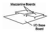
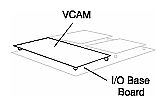
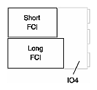
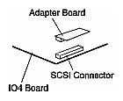
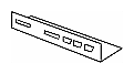
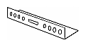
Figure 2-7, Figure 2-8, and Figure 2-9 show the locations of the standard controls, connectors, and indicators for the CHALLENGE/Onyx deskside systems. Table 2-2, Table 2-3, and Table 2-4describe each item.
Table 2-2. System Controls, Connectors, and Indicators
Item | Description |
|---|---|
This socket is an IEC320-C20 and accepts an IEC 320-C19 connector. | |
This circuit breaker switch controls the main power supply to the chassis and protects the system from electrical damage.
| |
This panel provides a display of current system operating conditions, such as temperature, power, and internal hardware status. If the system crashes, the system controller will record the events leading up to the failure. You can then retrieve these error messages for analysis. See the CHALLENGE/Onyx Diagnostic Roadmap (Document No. 108-7045-xxx) for a complete description. | |
Fault | The amber LED lights briefly when power is applied to the System Controller. This LED remains lit until the System Controller successfully initializes and a series of power-on tests have completed. |
Power on | This green LED glows when the system power switch is on and the DC power levels are normal. |
This three-position switch and the system key enable the user to bootup the system, reset the system, and perform system administrator tasks. See the CHALLENGE/Onyx Diagnostic Roadmap (Document No. 108-7045-xxx) for a complete description. |
 | Note: The key is the same for all system; however, the customer should make copies and keep them in a safe place. The system cannot boot without the key. In addition, to prevent possible tampering, the customer should not leave the system key in the lock during normal operation. |
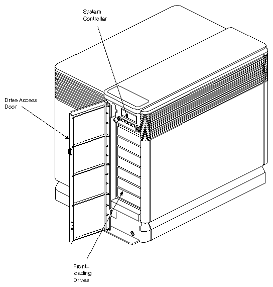
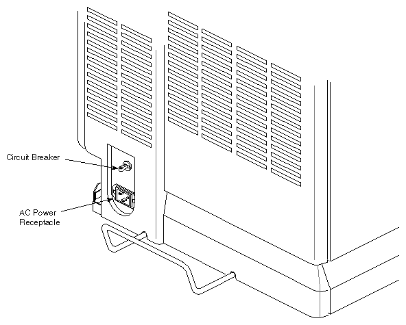
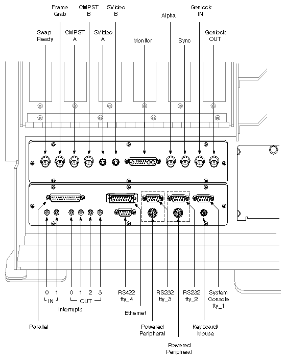
Table 2-3. I/O Panel Connectors
Item | Description |
|---|---|
Keyboard/Mouse Connector | This 6-pin minicircular dual inline (DIN) connector accepts the standard Silicon Graphics keyboard cable in Onyx systems. |
This is a 25-pin D-sub Centronics-compatible connector. | |
Ethernet | This 15-pin D-sub port provides a standard Ethernet connection. See note in Section 2.2.1, "I/O Filter Boards." |
A combination of 9-pin D-sub and 8-pin circular DIN connectors provides this serial interface. | |
This is a 9-pin connector. | |
0, 1 IN (Interrupt In) | This connector is used in multiple-system configurations to receive CPU interrupts from other CHALLENGE/Onyx deskside systems. |
0, 1, 2, 3 OUT (Interrupt Out) | This connector is used in multiple-system configurations to send an interrupt to other CHALLENGE/Onyx systems. |
 | Caution: Never remove the keyboard cable while the system is on. You may blow fuses on the main I/O panel. |
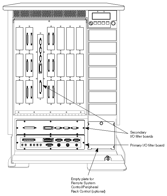
The I/O filter boards provide the secondary I/O panels that mount on the I/O door (see Figure 2-10). The filter boards connect to additional IO4 boards (if available) on a CHALLENGE server system. The CHALLENGE deskside system may have up to three IO4 boards. A system can therefore have up to two I/O filter boards and one main I/O panel board. The I/O filter board does not have a keyboard/mouse connection. Only the main I/O panel provides this connection.
The interrupt connectors 0, 1 IN and O, 1, 2, 3 OUT provide the capability to transmit and receive CPU interrupts to and from other CHALLENGE/Onyx systems. A single system can generate an interrupt to a maximum of four different systems. The following sections illustrate two possible examples for their use by customer-supplied application programs.
In this scenario, the customer uses the interrupts as a heartbeat transmitter, involving two systems working in tandem in a master/slave configuration. In this situation, the master computer sends continuous interrupts or heartbeats to a slave system to indicate normal, healthy operation. If, for some reason, the master computer goes down and fails to transmit an interrupt to the slave system, the slave system can automatically take control of the operation.
In another scenario, complex simulation programs may require that several computers be orchestrated to provide a comprehensive, yet cohesive, series of displays—for example, a multiple-scene flight simulation program. In this situation, different computers provide different environment, terrain, and situation scenery. A master orchestrating computer generates timed interrupts to the other systems to help signal and control the overall updating of frames and the changing of displayed events.
Table 2-4. Onyx Graphics I/O Panel Connectors
Connector | Function |
|---|---|
Separate video. These two electrically separate output channels enable you to connect an S-video recorder on one port and an S-video monitor on the other port. The channels are interchangeable. | |
13W3 | This output connector equals and replaces the RGB BNC connectors on earlier Silicon Graphics workstations. The 13W3 provides RGB out and logic sense for the monitor. |
SYNC | This output connector provides an external sync signal for non-Silicon Graphic monitors, as required. |
GEN IN | This input connector allows the system to line-lock to an external video source. |
GEN OUT | This output connector enables the master sync source to loop through the system to other equipment. |
ALPHA | This connector provides output for external transparent or color blending renderings. |
CMPST A | CMPST A and B provide a composite video output signal for a recording device and monitor. The channels are equal and interchangeable. |
This input connector provides acquisition control. | |
This input connector enables multiple systems to be slaved together to provide synchronous frame display. |
Table 2-5 and Table 2-6 and Figure 2-11 and Figure 2-12 describe the slot locations for the CHALLENGE/Onyx deskside system configurations.
Table 2-5. Onyx Graphics Configuration
Slot Number | Description |
|---|---|
1 | MC3 |
2 | IP19 CPU |
3 | IO4 base board (Note: An IO4 must reside in slot 3.) |
4 | VCAM board (Note: The VCAM mezzanine board connects to both the IO4 and the backplane.) |
5 | VME |
6 | VME |
7 | VME |
8 | GE10 (Geometry Engine) board |
9 | DG2 (Display Graphics) board |
10 | Third or fourth RM4 (Raster Manager) board |
11 | Second RM4 (Raster Manager) board |
12 | Third or fourth RM4 (Raster Manager) board |
13 | First RM4 (Raster Manager) board |
| Caution: Due to less air flow coming into slot 1 and because of the heat generated by the IP19 board, the cooler-operating MC3 must be in the first slot. |
| Note: The VCAM mezzanine board connects to both the IO4 board and the backplane. |
Table 2-6. CHALLENGE Server Configuration Slot Designations
Slot Number | Description |
|---|---|
1 | First MC3 |
2 | First CPU |
3 | Second or third CPU or second or third MC3 or second or third IO4 (See note below.) |
4 | Second or third CPU or second or third MC3 or second or third IO4 (See note below.) |
5 | IO4 Board (Note: An IO4 board must reside in slot 5.) |
6 | VCAM Board |
7 | VME |
8 | VME |
9 | VME |
10 | VME |
11 | VME |
| Caution: Owing to less air flow coming into slot 1 and because of the heat generated by the IP19 board, the cooler-operating MC3 must be in the first slot. |
| Note: The server system can have up to three CPU boards or three MC3 boards or three IO4 boards. See Chapter 3, "Configurations and Components," for a list of legal server configurations. In addition, an IO4 board must reside in slot 5. |
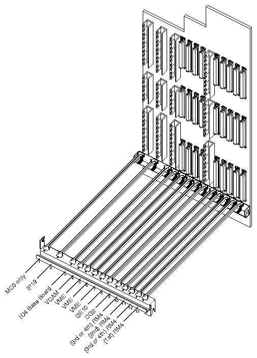
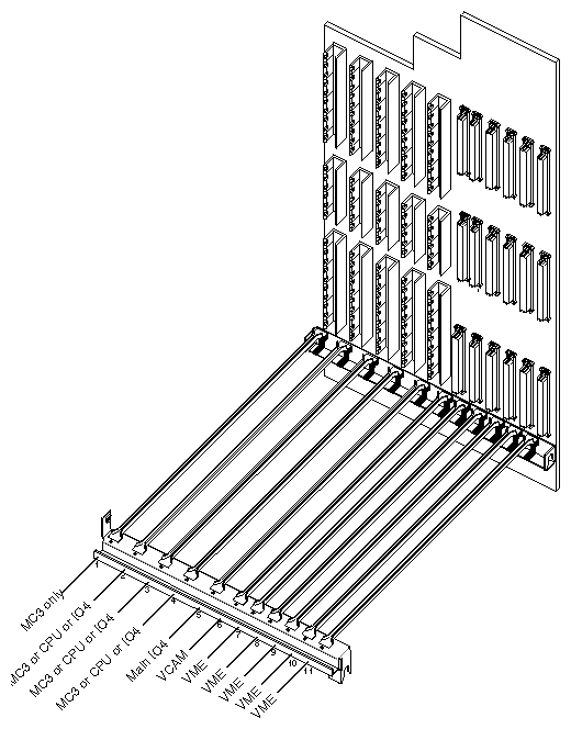
The CHALLENGE server system uses an 11-slot backplane to provide interconnection and power to the boards in the system. The Onyx graphics system uses a 13-slot backplane. Figure 2-13 and Figure 2-14 provide illustrations of the graphics and server backplanes.
The backplane provides two types of board connectors:
Slots 1 through 3 on the graphics configuration, which connect to the Everest bus, are 1.6 inches wide and use a male 560-pin Futurebus+™ Metral connector.
Slots 4 through 7 and 9 through 13 on the graphics configuration are 0.8 inches wide and use three 96-pin DIN connectors. Slot 8 uses a Futurebus+ Metral connector.
Note: Slots 4 through 7 on the graphics backplane connect to the VMEbus, and slots 8 through 13 connect to the graphics bus.
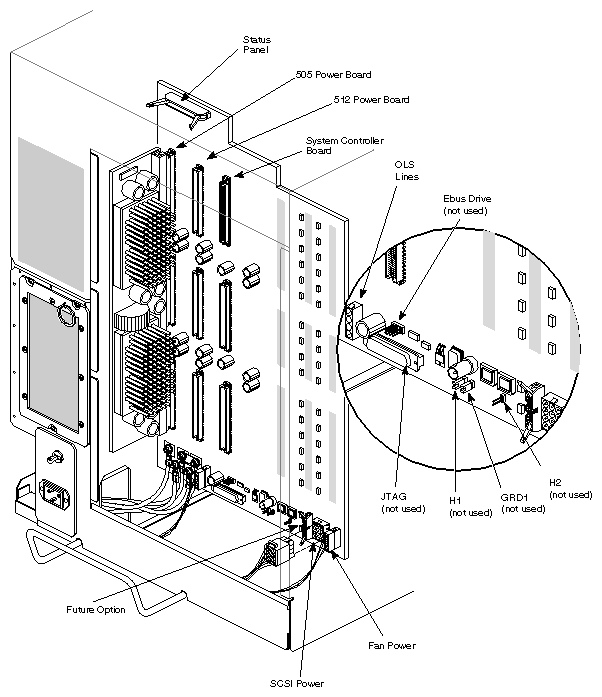
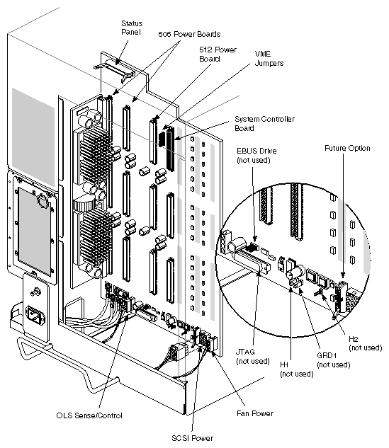
Figure 2-13 illustrates the Onyx graphics backplane. Note the power board connections (505, 512, and System Controller). The power boards convert the 48 DC volts from the offline switching (OLS) power supply to the required DC voltages for the boards. See the description in Chapter 4, "Theory of Operations," for more information on power board operation.
The graphics backplane employs two 505 boards, one 512 board, and one System Controller board. The 505 board provides 5 volts for use by the boards. The 512 provides both 5 volts and 12 volts. The 12 volts supply power to the drives, VME, and graphics boards.
| Note: The System Controller board is also known as the E Power board. |
The System Controller board provides 1.5 VDC for the Everest bus and also provides power for the system controller. This board can plug only in the rightmost slot because the connectors are different than the other power boards.
Table 2-7 describes additional backplane connectors and jumpers.
Table 2-7. Graphics and Server Backplane Connectors and Jumpers
Connector or Jumper | Description |
|---|---|
JTAG | This 25-pin connector is for factory use only, not for field or customer use. This connector provides an output connector for a logic analyzer. |
H1, GRD1, H2 | Do not change the setting of these jumpers. These headers are used by the factory to configure the system clock. |
The backplane provides two types of board connectors:
slots 1 through 5 on the server configuration which connect to the Everest bus, are 1.6 inches wide and use a male 560-pin metral connector
slots 6 through 11 on the server configuration, which connect to the VME bus, are 0.8 inches wide and use three 96-pin DIN connectors
Figure 2-14 illustrates the CHALLENGE server backplane. Note the power board connections (505, 512, and System Controller). The power boards convert the 48 DC volts from the offline switching (OLS) power supply to the required DC voltages for the boards. See the description in Chapter 4, "Theory of Operations," for more information on power board operation.
The server backplane employs one 505 board, one 512 board, and one System Controller board. The 505 board provides 5 volts for use by the boards. The 512 provides both 5 volts and 12 volts. The 12 volts supply power to the drives, VME, and graphics boards.
The System Controller board provides 1.5 VDC for the Everest bus and also provides power for the system controller. This board can plug only in the rightmost slot because the connectors are different than the other power boards.
Table 2-7 describes additional backplane connectors and jumpers.