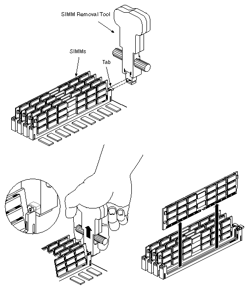
Use the SIMM extraction tool (see Figure 5-66) to remove SIMMs from the MC3 board.
 | Caution: Observe proper ESD practices (such as using a ground strap and an antistatic mat) when installing SIMMs. |
Place the extraction tool over the SIMM ejector tab as shown in Figure 5-66.
Grasp the SIMM extraction tool with your hand, then lift up the two stirrups on each side of the tool with your fingers.
Carefully remove the SIMMs and set them aside.
This section describes the installation and removal procedures for the field-replaceable units (FRUs) in the CHALLENGE/Onyx deskside system and contains information that is common to many maintenance activities.
Read the following subsections for safety information and general procedures.
Before beginning the replacement procedures, observe these precautions.
 | Warning: This equipment uses electrical power internally that is hazardous if the equipment is improperly disassembled. The procedures in this manual require specific training and technical knowledge and are for use only by Silicon Graphics system support engineers or other Silicon Graphics-trained personnel. |
| Caution: This equipment is extremely sensitive and susceptible to damage by electrostatic discharge (ESD). The buildup of electrical static potential on clothing and other materials may cause ESD. |
Use proper ESD preventive measures and observe these precautions:
Wear a properly grounded wrist strap when connecting and disconnecting peripherals.
Be sure that you and all the electrical equipment you handle are at ground potential to avoid damage from ESD. Do not rely on the power source ground: the ground is lost when the system is disconnected from the power source.
Keep boards in their antistatic bags until you are properly grounded to the chassis ground with a ground strap.
Do not use an ohmmeter or digital voltmeter on a board.
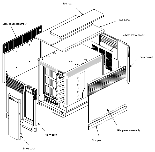
The CHALLENGE/Onyx deskside system uses sheet-metal housing and outer plastic panels. Two hinge pins and two plunger latches hold the chassis front door in place. The remaining panels attach to the sheet metal using ball and socket fasteners. Figure 5-67 provides an exploded view of the doors and panels.
Use these procedures to power down the system:
Ensure that the customer backs up the system, verifies the saved files, and makes sure that all users are off the target system.
Become superuser, then shut down the system software as follows:
# shutdown -y g0
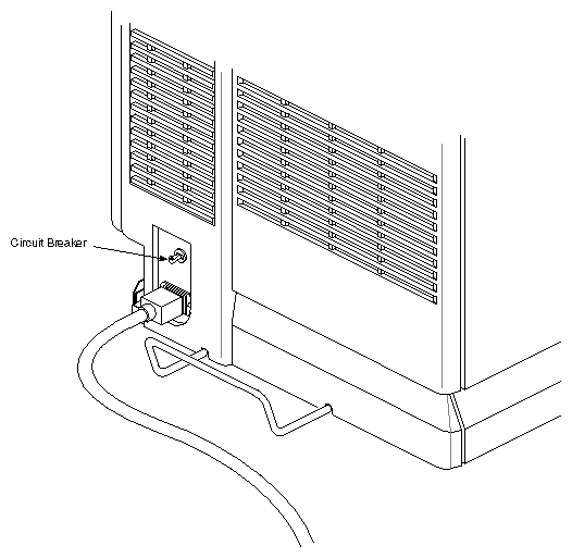
Power off the system. The switch is located in the rear of the chassis, near the AC power cord receptacle. See Figure 5-68. Disconnect the system from the power source.
Use these procedures to open the front door:
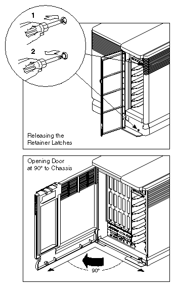
Open the drive door to expose the drives and front panel retainer latches.
Release the two retainer latches by fully depressing and releasing each latch with a pointed object, such as a screwdriver. Depress the inner button completely; Figure 5-69 shows the latch location and operation.
To close the front door, swing it to the closed position; then use a pointed object to fully depress and release the retainer latches.
Use these procedures to replace the front door:
Open the front door, as described in Section 5.16.3.
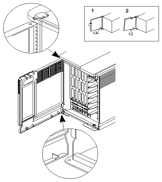
Grasp beneath the lower hinged corner of the front door. See Figure 5-70.
Lift the lower corner of the front door up and away from the lower hinge pin.
Drop the upper corner of the front door away from the upper hinge pin.
Reverse these steps to install the front door.
Follow these procedures to open the I/O door:
Power down the system, as described in Section 5.16.2, "Powering Down the System."
Open the chassis front door until it is perpendicular to its normal, closed position, as shown in Figure 5-69 (the chassis front must be in this position for the I/O door to open completely).
Label any unusual external cables and connectors to simplify reassembly.
Disconnect all external cables from their sheet-metal I/O connector plates above the door hinge, if necessary.
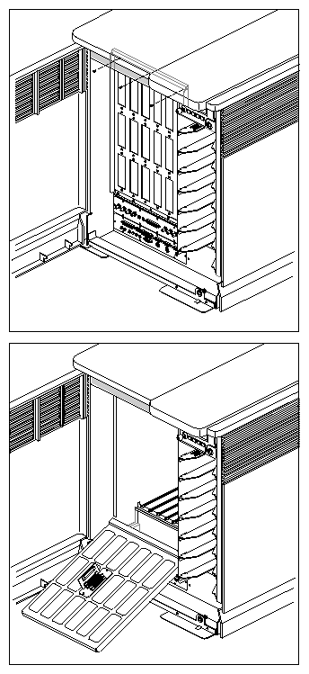
Release the I/O door by removing the three screws on the door's upper edge, as shown in Figure 5-71.
Lower the I/O door.
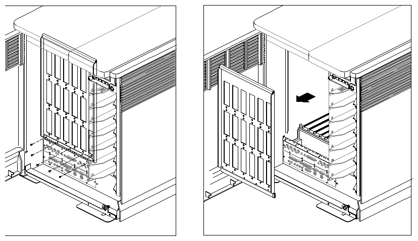
To remove the I/O door (P/N 013-0409-xxx), see Figure 5-72 and follow these steps:
Open the front door, as described in Section 5.16.3.
Open the I/O door, as described in Section 5.16.5, "Opening the I/O Door."
Disconnect the I/O plate connectors.
Remove the screws holding the I/O door hinge to the chassis.
Carefully remove the I/O door from the chassis.
Reverse these steps to install the I/O door.
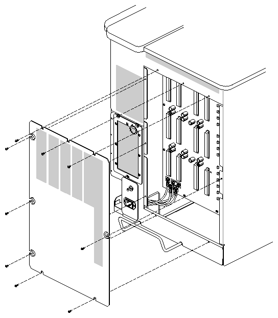
To remove the rear panel and sheet-metal cover, follow these procedures:
Power down the system, as described in Section 5.16.2, "Powering Down the System."
Loosen the back plastic panel from the chassis by grasping the bottom of the panel and giving it a quick pull away from the chassis.
Tilt the lower edge of the panel away from the chassis until it presses against the U-shaped bumper at the bottom of the chassis.
Drop the top edge of the panel down to clear the top hat.
Lift the panel away from the chassis.
Remove the sheet-metal panel from the chassis by partially removing the screws holding the door in place. Figure 5-73 shows the prepared back panel.
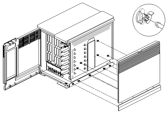
To remove the side panels (013-0343-xxx), see Figure 5-74 and follow these steps:
Follow these procedures to replace the top hat (P/N 050-0006-xxx):
Gently pry up the top hat with a flat-bladed screwdriver.
Lift the front edge of the top hat until it clears the top panel (see Figure 5-75).
Slide the top hat toward the rear of the chassis and remove the top hat from the chassis.
Reverse these steps to replace the top hat.
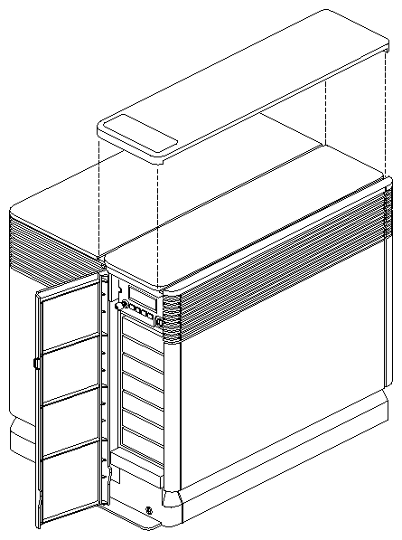
To replace the top panel (P/N 050-0007-xxx), see Figure 5-76 and follow these procedures:
Remove the right side panel, as described in Section 5.16.8, "Removing the Side Panels."
Locate the hidden catch plate centered along the right side of the top panel.
Press down on the catch plate with a flat-bladed screwdriver.
Slide the top panel from right to left. The top panel is now free.
To install the top panel, check that the hidden catch is bent slightly upward. Align the plastic fingers of the top panel with their corresponding slots and slide the panel right; the hidden catch plate engages automatically.
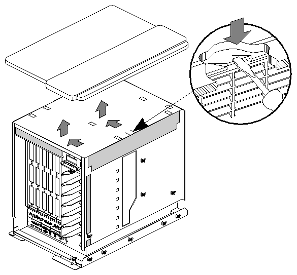
Figure 5-77 illustrates how to change the top hat label.
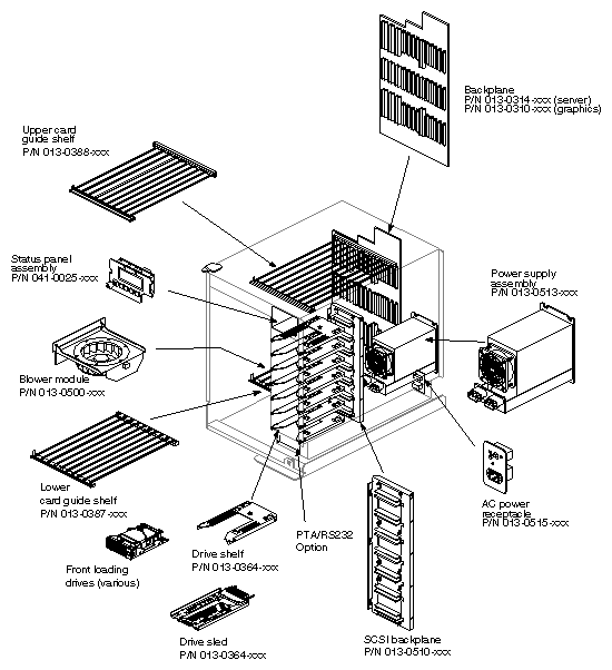
The following section provides instructions for replacing the field-replaceable units (FRUs). To replace an FRU, first use Figure 5-78 to identify the appropriate unit and its position in the chassis. Then proceed to the appropriate section and perform the steps.