This document introduces the CHALLENGE™/Onyx™ L deskside system (Model No. CMN A011) and provides the information necessary to install, configure, and test the system. This information is written for system support engineers (SSEs) or other authorized Silicon Graphics® employees who are responsible for the installation of these systems.
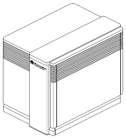
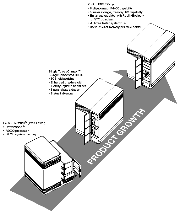
The multiprocessor CHALLENGE L and Onyx L (hereinafter called the CHALLENGE/Onyx deskside) systems are an evolutionary enhancement over previous- generation Silicon Graphics deskside systems such as the 12-slot and 15-slot twin towers and 13-slot and 14-slot Single Towers. See Figure 1-1 and Figure 1-2.
Externally, the CHALLENGE (server) and the Onyx (graphics) deskside systems closely resemble the Single Tower and Crimson™ systems (previous generation Silicon Graphics deskside computers). These systems all use a similar chassis type, covers, drive and I/O doors; however, internally, the CHALLENGE/Onyx L system differs radically from the older-style systems and incorporates a complete redesign in comparison with the previous deskside system architecture. The CHALLENGE/Onyx deskside chassis has also undergone some subtle, but highly effective, changes that have contributed to the systems overall improvement. These internal and external improvements include
greater internal storage capacity (The new chassis design supports up to seven internal drives.)
greater main memory (up to 2 GB of RAM per MC3 using 64 MB SIMMs)
memory interleaving for faster memory accessing
more and faster CPUs (from 2 to 12 MIPS® R4400™ processors in the server configuration and from two to four processors in the graphics system)
more I/O channels using add-on SCSI mezzanine boards and optional I/O connectivity
enhanced graphics with the RealityEngine2™ or VTX™ graphics board set
improved system cooling
In addition, the CHALLENGE/Onyx deskside system provides these new key features:
Other distinguishing features of this system include
single chassis for both drives and cards
dual small computer system interface (SCSI) channels
all front-loading drives (FLDs)

Note: The CHALLENGE/Onyx system use a new front loading mounting device, a slide-lever sled design that is slimmer and less bulkier than the previous manual push-button tray model. In addition, the new sled mechanically inserts the drive into the bay to reduce possible shock to the drive.
If you read many Silicon Graphics documents, or talk with various organizations in the company, you may encounter different terminology being used for the same concepts. To avoid confusion, Table 1-1 provides a list of these terms and their marketing and in-house aliases.
Table 1-1. CHALLENGE/Onyx Multiname Terms
Marketing Term | In-house Name | Term Used in This Manual |
|---|---|---|
CHALLENGE L and Onyx L deskside and CHALLENGE XL and Onyx XL rackmount systems | Everest | CHALLENGE/Onyx deskside and rackmount systems |
CHALLENGE L and Onyx L deskside systems | Eveready | CHALLENGE/Onyx deskside systems |
CHALLENGE XL and Onyx XL rackmount systems | Terminator | CHALLENGE/Onyx rackmount systems |
CHALLENGEvault | CHALLENGE Vault | |
RealityEngine2 | Mirage | RealityEngine2 |
POWERpath-2 | Everest system architecture | Everest system architecture |
POWERpath-2 SYSTEM bus | Everest bus or Ebus | Everest bus or Ebus |
POWERpath-2 Interleaved Memory board | MC3 | MC3 |
POWERpath-2 I/O board | IO4 board | IO4 board |
HIO bus | Ibus | Ibus |
HIO modules | Mezz cards | Mezz cards |
IRIX release 4D1-5.0 | Sherwood | IRIX™ -5.0 |
Read these safety statements carefully before you install or remove any part of the system.
 | Warning: Installation of this product requires specific training and technical knowledge. These instructions have been provided for the use of Silicon Graphics system support engineers (SSEs), or Silicon Graphics-trained personnel only. This equipment uses electrical power internally that is hazardous if the equipment is improperly assembled or disassembled. |
| Warning: There is a danger of explosion if the lithium battery-powered integrated circuits on the IO4 and System Controller boards are incorrectly replaced. Replace only with Dallas Semiconductor P/N 051397. Discard the used part according to the manufacturer's instructions. |
 | Caution: This equipment is extremely sensitive to damage from electrostatic discharge (ESD), an electrical charge caused by the buildup of electrical potential on clothing and other materials. You must use the following ESD preventive measures: |
Attach a ground strap to your wrist when connecting/disconnecting boards or peripherals.
Ensure that you and all electrical equipment that you handle during this installation are at ground potential to avoid damage from ESD.
Keep the boards in the provided antistatic bags until they are needed.
Do not place boards on top of the antistatic bag unless the outside of the bag also has antistatic protection. If you are not sure that the outside of the bag is protected, place the boards on top of an antistatic mat.
Remove a board from its antistatic bag only when you are properly grounded to the chassis ground with a ground strap.
Do not disconnect the power cord from the wall socket and the chassis if you are servicing a system or installing a hardware upgrade. You will lose the system ground and could damage the equipment as a result.
Do not use an ohmmeter on the boards.
| Caution: There are 14 fuses installed on the SCSI backplane. These normally are not field replaceable, because they are soldered directly onto the backplane. However, for continued protection against risk of fire, replace them only with a Cooper Industries, Bussman Div., P/N MCR-5, 125 V, 5 A-rated fuse. |