This chapter provides instructions for installing the IRIS ATM network interface controller board into a CHALLENGE™ or Onyx™ server or supercomputer. There is a separate section for ecah of the following Silicon Graphics' platforms:
CHALLENGE and POWER CHALLENGE L Deskside
CHALLENGE and POWER CHALLENGE XL Rackmount
Onyx and POWER Onyx Deskside
Onyx and POWER Onyx Rackmount
This section describes installing the IRIS ATM network board into a CHALLENGE or POWER CHALLENGE L Deskside server. These platforms support a maximum of 6 IRIS ATM boards.
Before starting the installation, prepare yourself and the equipment by following the instructions in this section.
Verify that the IRIS ATM package is complete. It should contain the items listed in Table 2-1. If anything is missing, do not proceed with the installation. Contact the customer or the customer's salesperson.
Table 2-1. ATM Package Contents
Item | Quantity |
|---|---|
CD-ROM with IRIS ATM software and IRIS ATM Release Notes | 1 |
IRIS ATM short mezzanine board | 1 |
Internal fiber optic cable assembly | 2 fiber optic lines and |
2-port panel plate: replacement for 1-port plate in multiple-board installations | 1 |
Sheets of labels | 4 |
Screws to attach IRIS ATM board to IO4 board | 4 |
IRIS ATM API Programmer's Guide (document) | 1 |
IRIS ATM Configuration Guide (document) | 1 |
The IRIS ATM board has a set of jumpers called the Unit Jumper Set, illustrated in Figure 1-2. These jumpers must be configured to give the board a unique unit identification number (for example, ATM unit 0, ATM unit 1, etc.). Follow the instructions in Section 1.2 in Chapter 1 to set the jumpers.
 | Note: If two or more installed boards have the same unit number, the first board that the operating system locates is initialized and brought into operation, but the duplicates are not. When the system encounters each duplicate board, it prints an error message, then skips the board without initializing it. The command /sbin/hinv does not list uninitialized boards, and they do not have device files in the /dev directory. |
Follow the steps in this section to prepare the CHALLENGE L Deskside system for installation.
 | Caution: This equipment is extremely sensitive and susceptible to damage by electrostatic discharge (ESD), a spark caused by the buildup of electrical static potential on clothing and other material. You must use proper ESD preventive measures as explained in the "Safety" section of the CHALLENGE/Onyx Deskside Installation Instructions. |
Use the command below to verify that the IRIX operating system is the correct version for this IRIS ATM release. The IRIS ATM Release Notes indicate the correct version. Do not proceed until the correct version of IRIX is installed.
% versions eoe1
I  eoe1  date  Execution Only Environment 1, version
Verify that the file system is backed up.
Install the IRIS ATM software. Step-by-step instructions are provided in the IRIS ATM Release Notes. Do not proceed until the new IRIS ATM software is installed.

Warning: Failure to install the software before installing the board may destroy the MAC address on the board. It this occurs, the board cannot function. Configure the IRIS ATM software. Step-by-step instructions are provided in the IRIS ATM Configuration Guide.
Note: You cannot verify successful installation of the board until the software is configured. If you choose not to configure the software now, you will need to do so before you can test the board's functionality. In addition, selecting to configure later will require an additional reboot of the system. Shut down the system by turning the key on the System Controller panel (located at the front) to OFF.
Wait a minute for the system to shut down, then switch the circuit breaker on the back to OFF.
| Warning:
Failure to turn off the circuit breaker may result in electrical shock. Failure to wait for the system to shut down may cause irreparable damage to system components or data. |
Open the front door and pull down the I/O panel in the front of the chassis to expose the IO4 boards, as illustrated in Figure 2-1.
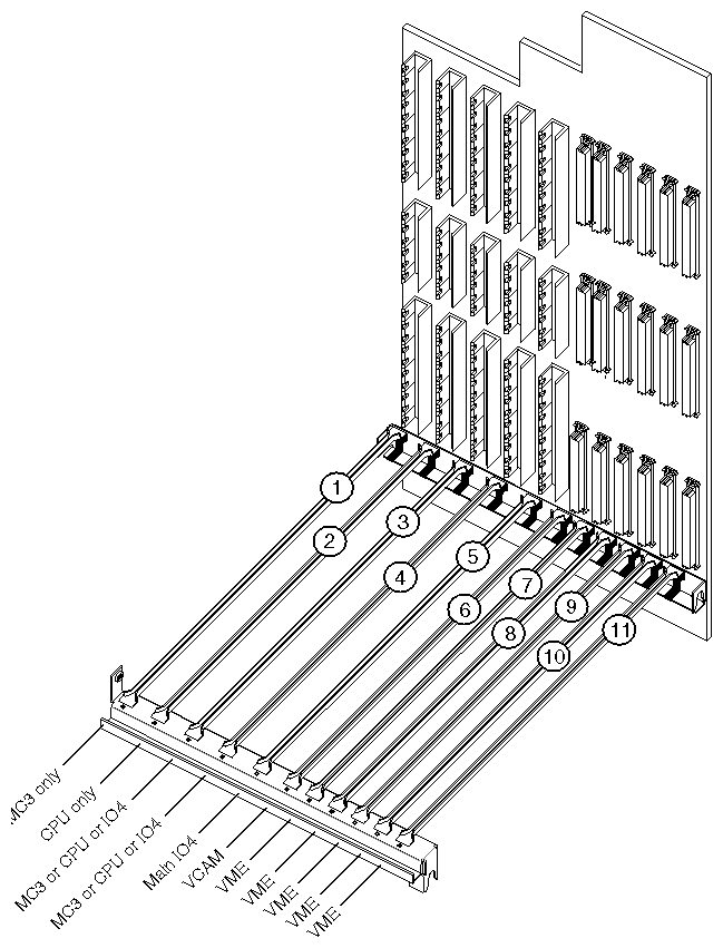
The IRIS ATM board requires one short mezzanine slot on an IO4 board. This section describes how to select an appropriate slot for each IRIS ATM board.
| Caution: This equipment is extremely sensitive and susceptible to damage by electrostatic discharge (ESD), a spark caused by the buildup of electrical static potential on clothing and other material. You must use proper ESD preventive measures as explained in the "Safety" section of the CHALLENGE/Onyx Deskside Installation Instructions. |
Locate the IO4 boards that are currently installed. Slot 5 always has an IO4 board. (See Figure 2-1 for an illustration of the slots.) In addition, slots 3 and/or 4, may contain IO4 boards. A CHALLENGE L may have one to three IO4 boards installed. Each IO4 board has two mezzanine slots, as illustrated in Figure 2-2. The ATM board may be installed on any of the available mezzanine slots, as detailed below:
If the system has only one IO4 board, this is the location for the IRIS ATM board. The ATM board may be installed in either the upper or lower position on the IO4 board, as illustrated in Figure 2-2.
If the system has more than one IO4 board, you may select any unoccupied mezzanine slot.
If there are no unoccupied mezzanine slots, you must install another IO4 board. Contact the sales representative to order one. The installation cannot be continued until a mezzanine slot is available.
Note: The maximum number of IO4 boards for a CHALLENGE L Deskside system is three. If three IO4 boards are already installed, and if all the mezzanine slots are occupied, IRIS ATM cannot be installed onto this system.
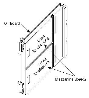
Follow the steps below to install the IRIS ATM board.
Remove the IO4 board that you have selected from the CHALLENGE chassis.
Lay the board on a flat antistatic surface so that the component side faces up and the SCSI connectors face toward you, as illustrated in Figure 2-3.
Locate the selected mezzanine slot (upper or lower) and remove the four screws from the standoffs, as illustrated in Figure 2-3. If the screws are missing, this is not a problem.
Position the IRIS ATM board onto the selected slot so that the connector on the bottom of the board matches the receptacle on the IO4 board and the standoffs match the ATM board's holes. Figure 2-3 illustrates the correct positioning for the upper and lower slots.
Replace the standoff screws. These screws have a "float" feature, and do not tighten. If necessary, use the screws that are shipped with the IRIS ATM package.
Reinstall the IO4 board into the chassis, as illustrated in Figure 2-4. Push the board firmly into the backplane. If the board has a VCAM board, the VCAM board must also seat into the backplane.
Create an adapter identification for the ATM mezzanine board. The identification has the format F-XX-5 for the lower slot and F-XX-6 for the upper slot, where XX is the slot number where the IO4 board resides. For example, a mezzanine board in the upper position (IO adapter 6) on the main IO4 board located in slot 5 is labelled F-05-6.
From the sheets of labels, remove a small-sized label with the identification created in the previous step. Attach the label to the outside of the ATM I/O panel plate that is attached to the internal cable assembly (illustrated in Figure 2-5).
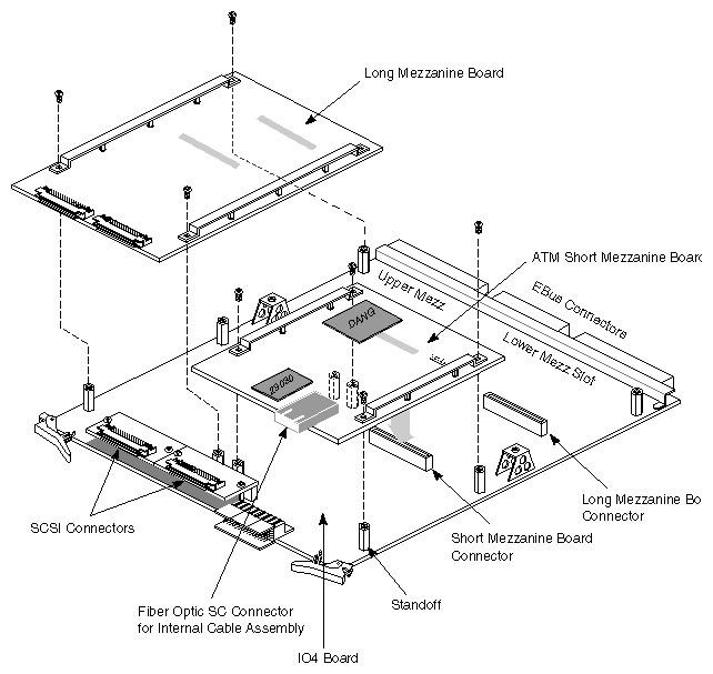
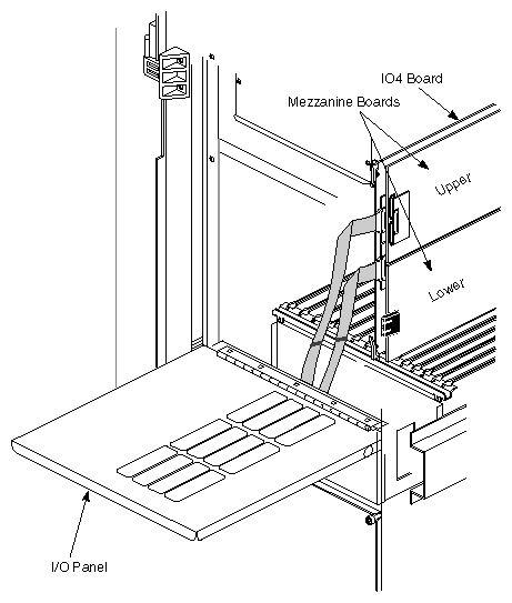
Follow the steps below to attach the internal ATM cables to the ATM board and the panel plate to the card cage's I/O panel.
| Caution: Do not touch the fiber optic material exposed at the ends of the cable. Do not leave the cable ends uncapped. Performance of the fiber optic cable can seriously degrade due to grease or dust. |
Locate the internal cable assembly that consists of two fiber optic lines terminated inside an SC connector at one end and a MIC receptable attached to the ATM I/O panel plate at the other end, as illustrated in Figure 2-5.
| Note: For installations with multiple IRIS ATM boards, replace the single-port panel plate on the cable assembly with the 2-port panel plate that is shipped with the product. |
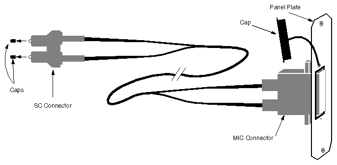
Remove one blank panel plate from the system's I/O panel and install the ATM panel plate.
Remove the protective caps from the SC connector.
Slide the SC connector into the ATM board's fiber optic receptacle. To ensure proper orientation, the SC plug has guide ridges that must slide into slots in the receptacle.
Close the I/O door and the chassis door.
The ATM connector provided at the ATM IO panel plate is a female, S-type MIC connector. The site's ATM cable for this connection must be multi-mode fiber optic cable terminated with a male MIC connector (S-, A-, and B-types are all compatible).
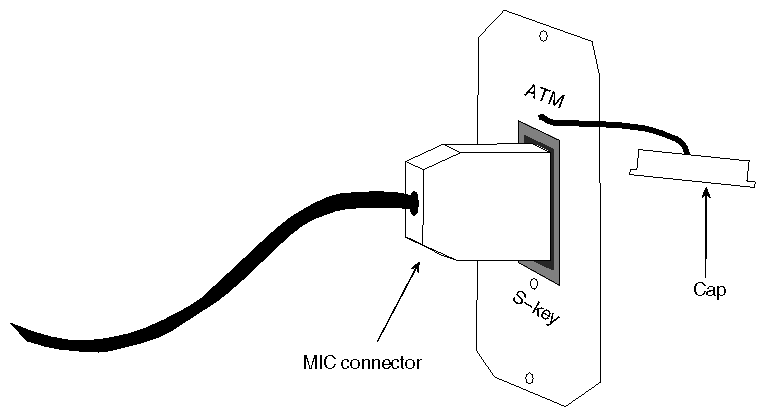
Remove the protective cap from the port on the ATM panel plate and attach the site's fiber optic cable to the system's ATM panel plate, as illustrated in Figure 2-6. The connection should snap (or click) into place.
| Note: MIC connectors are "keyed" so that they snap into place only when appropriate types are being connected and correct positioning is being used. If the connection does not snap into place, try a different position. If that does not solve the problem verify that the MIC has been designed to mate with an S-type receptacle. |
To finish the installation, do the following:
Flip the circuit breaker on the back of the chassis to ON, then turn the key switch on the front to ON.
When the console prompts you with the question Automatically reconfigure the operating system?, answer yes or y in order to build a new kernel.
Note: If this prompt does not appear, you probably have not installed the IRIS ATM software. Instead of proceeding with the steps below, follow the instructions in the IRIS ATM Release Notes to install and configure the software. Logon and reboot (this is the second time this system is being started) to begin using the newly built operating system. The command lines below can be used to accomplish this step:
% su
Password: thepassword
# reboot
Logon and invoke hinv to verify that the IRIS ATM hardware is listed:
% /sbin/hinv
. . .
ATM OC-3c unit#: slot#, adapter#
where unit# reflects the current setting of the board's Unit Jumper Set or the unit number assigned by the driver (depending on the assignment mode configured in the /var/sysgen/master.d/atm file), slot# indicates the slot in which the IO4 board resides, and adapter# (IO4 adapter) indicates the mezzanine position where the ATM board resides.
Note: If the board is not listed, either (1) the system is running the wrong version of IRIX, (2) the newly installed board's jumpers have the same unit number as one of the ATM boards that are listed, or (3) the board is improperly installed. If no ATM board is listed, use the versions eoe1 command to verify the version of IRIX. If the version is correct or if other IRIS ATM boards are listed, reinstall the product (the board and all cables) making sure to set the jumpers correctly and to seat all the hardware firmly. Follow the instructions in the IRIS ATM Configuration Guide to verify that upper layer applications can send and receive over the ATM subsystem.
This section describes installing the IRIS ATM network board into a CHALLENGE or POWER CHALLENGE XL Rackmount server. The maximum number of IRIS ATM boards for this chassis varies, depending on the system's configuration; however, for most configurations the maximum is 8.
Before starting the installation, prepare yourself and the equipment by following the instructions in this section.
Verify that the IRIS ATM package is complete. It should contain the items listed in Table 2-2. If anything is missing, do not proceed with the installation. Contact the customer or the customer's salesperson.
Table 2-2. ATM Package Contents
Item | Quantity |
|---|---|
CD-ROM with IRIS ATM software and IRIS ATM Release Notes | 1 |
IRIS ATM short mezzanine board | 1 |
Internal fiber optic cable assembly with a 1-port panel plate attached | 2 fiber optic lines and |
2-port panel plate: replacement for 1-port plate in multiple-board installations | 1 |
Sheets of labels | 4 |
Screws to attach IRIS ATM board to IO4 board | 4 |
IRIS ATM API Programmer's Guide (document) | 1 |
IRIS ATM Configuration Guide (document) | 1 |
The IRIS ATM board has a set of jumpers called the Unit Jumper Set, illustrated in Figure 1-2. These jumpers must be configured to give the board a unique unit identification number (for example, ATM unit 0, ATM unit 1, etc.). Follow the instructions in Section 1.2 in Chapter 1 to set the jumpers.
| Note: If two or more installed boards have the same unit number, the first board that the operating system locates is initialized and brought into operation, but the duplicates are not. When the system encounters each duplicate board, it prints an error message, then skips the board without initializing it. The command /sbin/hinv does not list uninitialized boards, and they do not have device files in the /dev directory. |
Follow the steps in this section to prepare the CHALLENGE XL Rackmount system for installation.
| Caution: This equipment is extremely sensitive and susceptible to damage by electrostatic discharge (ESD), a spark caused by the buildup of electrical static potential on clothing and other material. You must use proper ESD preventive measures as explained in the "Safety" section of the CHALLENGE/Onyx XL Rackmount Installation Instructions. |
Use the command below to verify that the IRIX operating system is the correct version for this IRIS ATM release. The IRIS ATM Release Notes indicate the correct version. Do not proceed until the correct version of IRIX is installed.
% versions eoe1
I  eoe1  date  Execution Only Environment 1, version
Verify that the file system is backed up.
Install the IRIS ATM software. Step-by-step instructions are provided in the IRIS ATM Release Notes. Do not proceed until the new IRIS ATM software is installed.
Warning: Failure to install the software before installing the board may destroy the MAC address on the board. It this occurs, the board cannot function. Configure the IRIS ATM software. Step-by-step instructions are provided in the IRIS ATM Configuration Guide.
Note: You cannot verify successful installation of the board until the software is configured. If you choose not to configure the software now, you will need to do so before you can test the board's functionality. In addition, selecting to configure later will require an additional reboot of the system. Shut down the system by turning the key on the System Controller panel (located at the front) to OFF.
Wait a minute for the system to shut down, then switch the power switch on the lower front corner of the chassis to OFF.
| Warning: Failure to turn off the circuit breaker may result in electrical shock. Failure to wait for the system to shut down may cause irreparable damage to system components or data. |
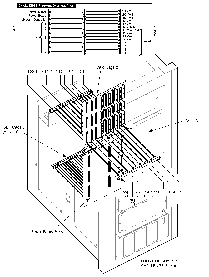
Open the back door and pull down the I/O panel for card cage 2 to expose the IO4 boards and VMEBus slots, as illustrated in Figure 2-7.
The IRIS ATM board requires one short mezzanine slot on an IO4 board. This section describes how to select an appropriate slot for each IRIS ATM board.
| Caution: This equipment is extremely sensitive and susceptible to damage by electrostatic discharge (ESD), a spark caused by the buildup of electrical static potential on clothing and other material. You must use proper ESD preventive measures as explained in the "Safety" section of the CHALLENGE/Onyx Rackmount Installation Instructions. |
Locate the IO4 boards that are currently installed. Slot 15 always has an IO4 board. (See Figure 2-7 for an illustration of the slots.) In addition, slots 13, 11, 9, 7 and/or 5, may contain IO4 boards. A CHALLENGE XL may have one to six IO4 boards installed. Each IO4 board has two mezzanine slots, as illustrated in Figure 2-8. The ATM board may be installed on any of the available mezzanine slots, as detailed below:
If the system has only one IO4 board, this is the location for the IRIS ATM board. The ATM board may be installed in either the upper or lower position on the IO4 board, as illustrated in Figure 2-8.
If the system has more than one IO4 board, you may select any unoccupied mezzanine slot.
If there are no unoccupied mezzanine slots, you must install another IO4 board. Contact the sales representative to order one. The installation cannot be continued until a mezzanine slot is available.
Note: The maximum number of IO4 boards for a CHALLENGE XL Rackmount system varies, but is usually four. If four IO4 boards are already installed, and if all the mezzanine slots are occupied, IRIS ATM probably cannot be installed onto this system.
Follow the steps below to install the IRIS ATM board.
Remove the IO4 board that you have selected from the CHALLENGE chassis.
Lay the board on a flat antistatic surface so that the component side faces up and the SCSI connectors face toward you, as illustrated in Figure 2-9.
Locate the selected mezzanine slot (upper or lower) and remove the four screws from the standoffs, as illustrated in Figure 2-9. If the screws are missing, this is not a problem.
Position the IRIS ATM board onto the selected slot so that the connector on the bottom of the board matches the receptacle on the IO4 board and the standoffs match the ATM board's holes. Figure 2-9 illustrates the correct positioning for the upper and lower slots.
Replace the standoff screws. These screws have a "float" feature, and do not tighten. If necessary, use the screws that are shipped with the IRIS ATM package.
Reinstall the IO4 board into the chassis, as illustrated in Figure 2-10. Push the board firmly into the backplane. If the board has a VCAM board, the VCAM board must also seat into the backplane.
Create an adapter identification for the ATM mezzanine board. The identification has the format F-XX-5 for the lower slot and F-XX-6 for the upper slot, where XX is the slot number where the IO4 board resides. For example, a mezzanine board in the upper position (IO adapter 6) on the main IO4 board located in slot 15 is labelled F-15-6.
From the sheets of labels, remove a small-sized label with the identification created in the previous step. Attach the label to the outside of the ATM I/O panel plate that is attached to the internal cable assembly (illustrated in Figure 2-11).
Follow the steps below to attach the internal ATM cables to the ATM board and the panel plate to the card cage's I/O panel.
| Caution: Do not touch the fiber optic material exposed at the ends of the cable. Do not leave the cable ends uncapped. Performance of the fiber optic cable can seriously degrade due to grease or dust. |
Locate the internal cable assembly that consists of two fiber optic lines terminated inside an SC connector at one end and a MIC receptable attached to the ATM I/O panel plate at the other end, as illustrated in Figure 2-11.
Note: For installations with multiple IRIS ATM boards, replace the single-port panel plate on the cable assembly with the 2-port panel plate that is shipped with the product.
Remove one blank panel plate from the system's I/O panel and install the ATM panel plate.
Remove the protective caps from the SC connector.
Slide the SC connector into the ATM board's fiber optic receptacle. To ensure proper orientation, the SC plug has guide ridges that must slide into slots in the receptacle.
Close the I/O door and the chassis door.
The ATM connector provided at the ATM IO panel plate is a female, S-type MIC connector. The site's ATM cable for this connection must be multi-mode fiber optic cable terminated with a male MIC connector (S-, A-, and B-types are all compatible).
Remove the protective cap from the port on the ATM panel plate and attach the site's fiber optic cable to the system's ATM panel plate, as illustrated in Figure 2-12. The connection should snap (or click) into place.
| Note: MIC connectors are "keyed" so that they snap into place only when appropriate types are being connected and correct positioning is being used. If the connection does not snap into place, try a different position. If that does not solve the problem verify that the MIC has been designed to mate with an S-type receptacle. |
To finish the installation, do the following:
Flip the circuit breaker on the back of the chassis to ON, then turn the key switch on the front to ON.
When the console prompts you with the question Automatically reconfigure the operating system?, answer yes or y in order to build a new kernel.
Note: If this prompt does not appear, you probably have not installed the IRIS ATM software. Instead of proceeding with the steps below, follow the instructions in the IRIS ATM Release Notes to install and configure the software. Logon and reboot (this is the second time this system is being started) to begin using the newly built operating system. The command lines below can be used to accomplish this step:
% su
Password: thepassword
# reboot
Logon and invoke hinv to verify that the IRIS ATM hardware is listed:
% /sbin/hinv
. . .
ATM OC-3c unit#: slot#, adapter#
where unit# reflects the current setting of the board's Unit Jumper Set or the unit number assigned by the driver (depending on the assignment mode configured in the /var/sysgen/master.d/atm file), slot# indicates the slot in which the IO4 board resides, and adapter# (IO4 adapter) indicates the mezzanine position where the ATM board resides.
Note: If the board is not listed, either (1) the system is running the wrong version of IRIX, (2) the newly installed board's jumpers have the same unit number as one of the ATM boards that are listed, or (3) the board is improperly installed. If no ATM board is listed, use the versions eoe1 command to verify the version of IRIX. If the version is correct or if other IRIS ATM boards are listed, reinstall the product (the board and all cables) making sure to set the jumpers correctly and to seat all the hardware firmly. Follow the instructions in the IRIS ATM Configuration Guide to verify that upper layer applications can send and receive over the ATM subsystem.
This section describes installing the IRIS ATM network board into a Onyx or POWER Onyx Deskside server. These platforms support a maximum of 2 IRIS ATM boards.
Before starting the installation, prepare yourself and the equipment by following the instructions in this section.
Verify that the IRIS ATM package is complete. It should contain the items listed in Table 2-3. If anything is missing, do not proceed with the installation. Contact the customer or the customer's salesperson.
Table 2-3. ATM Package Contents
Item | Quantity |
|---|---|
CD-ROM with IRIS ATM software and IRIS ATM Release Notes | 1 |
IRIS ATM short mezzanine board | 1 |
Internal fiber optic cable assembly | 2 fiber optic lines and |
2-port panel plate: replacement for 1-port plate in multiple-board installations | 1 |
Sheets of labels | 4 |
Screws to attach IRIS ATM board to IO4 board | 4 |
IRIS ATM API Programmer's Guide (document) | 1 |
IRIS ATM Configuration Guide (document) | 1 |
The IRIS ATM board has a set of jumpers called the Unit Jumper Set, illustrated in Figure 1-2. These jumpers must be configured to give the board a unique unit identification number (for example, ATM unit 0, ATM unit 1, etc.). Follow the instructions in Section 1.2 in Chapter 1 to set the jumpers.
| Note: If two or more installed boards have the same unit number, the first board that the operating system locates is initialized and brought into operation, but the duplicates are not. When the system encounters each duplicate board, it prints an error message, then skips the board without initializing it. The command /sbin/hinv does not list uninitialized boards, and they do not have device files in the /dev directory. |
Follow the steps in this section to prepare the Onyx Deskside system for installation.
| Caution: This equipment is extremely sensitive and susceptible to damage by electrostatic discharge (ESD), a spark caused by the buildup of electrical static potential on clothing and other material. You must use proper ESD preventive measures as explained in the "Safety" section of the CHALLENGE/Onyx Deskside Installation Instructions. |
Use the command below to verify that the IRIX operating system is the correct version for this IRIS ATM release. The IRIS ATM Release Notes indicate the correct version. Do not proceed until the correct version of IRIX is installed.
% versions eoe1
I  eoe1  date  Execution Only Environment 1, version
Verify that the file system is backed up.
Install the IRIS ATM software. Step-by-step instructions are provided in the IRIS ATM Release Notes. Do not proceed until the new IRIS ATM software is installed.
Warning: Failure to install the software before installing the board may destroy the MAC address on the board. It this occurs, the board cannot function. Configure the IRIS ATM software. Step-by-step instructions are provided in the IRIS ATM Configuration Guide.
Note: You cannot verify successful installation of the board until the software is configured. If you choose not to configure the software now, you will need to do so before you can test the board's functionality. In addition, selecting to configure later will require an additional reboot of the system. Shut down the system by turning the key on the System Controller panel (located at the front) to OFF.
Wait a minute for the system to shut down, then switch the circuit breaker on the back to OFF.
| Warning:
Failure to turn off the circuit breaker may result in electrical shock. Failure to wait for the system to shut down may cause irreparable damage to system components or data. |
Open the front door and pull down the I/O panel in the front of the chassis to expose the IO4 boards, as illustrated in Figure 2-13.
The IRIS ATM board requires one short mezzanine slot on an IO4 board. This section describes how to select an appropriate slot for each IRIS ATM board.
| Caution: This equipment is extremely sensitive and susceptible to damage by electrostatic discharge (ESD), a spark caused by the buildup of electrical static potential on clothing and other material. You must use proper ESD preventive measures as explained in the "Safety" section of the CHALLENGE/Onyx Deskside Installation Instructions. |
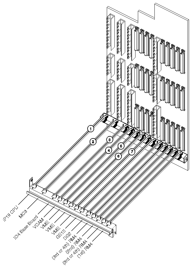
Locate the IO4 board that is installed in Slot 3. The IO4 board has two mezzanine slots, as illustrated in Figure 2-14. The ATM board may be installed on either of these mezzanine slots.
| Note: The maximum number of IO4 boards for an Onyx Deskside system is one. If both mezzanine slots are occupied, IRIS ATM cannot be installed onto this system. |
Follow the steps below to install the IRIS ATM board.
Remove the IO4 board that you have selected from the chassis.
Lay the board on a flat antistatic surface so that the component side faces up and the SCSI connectors face toward you, as illustrated in Figure 2-15.
Locate the selected mezzanine slot (upper or lower) and remove the four screws from the standoffs, as illustrated in Figure 2-15. If the screws are missing, this is not a problem.
Position the IRIS ATM board onto the selected slot so that the connector on the bottom of the board matches the receptacle on the IO4 board and the standoffs match the ATM board's holes. Figure 2-15 illustrates the correct positioning for the upper and lower slots.
Replace the standoff screws. These screws have a "float" feature, and do not tighten. If necessary, use the screws that are shipped with the IRIS ATM package.
Reinstall the IO4 board into the chassis, as illustrated in Figure 2-16. Push the board firmly into the backplane. If the board has a VCAM board, the VCAM board must also seat into the backplane.
Create an adapter identification for the ATM mezzanine board. The identification has the format F-03-5 for the lower slot and F-03-6 for the upper slot.
From the sheets of labels, remove a small-sized label with the identification created in the previous step. Attach the label to the outside of the ATM I/O panel plate that is attached to the internal cable assembly (illustrated in Figure 2-17).
Follow the steps below to attach the internal ATM cables to the ATM board and the panel plate to the card cage's I/O panel.
| Caution: Do not touch the fiber optic material exposed at the ends of the cable. Do not leave the cable ends uncapped. Performance of the fiber optic cable can seriously degrade due to grease or dust. |
Locate the internal cable assembly that consists of two fiber optic lines terminated inside an SC connector at one end and a MIC receptable attached to the ATM I/O panel plate at the other end.
| Note: For installations with multiple IRIS ATM boards, replace the single-port panel plate on the cable assembly with the 2-port panel plate that is shipped with the product. |
Remove one blank panel plate from the system's I/O panel and install the ATM panel plate.
Remove the protective caps from the SC connector.
Slide the SC connector into the ATM board's fiber optic receptacle. To ensure proper orientation, the SC plug has guide ridges that must slide into slots in the receptacle.
Close the I/O door and the chassis door.
The ATM connector provided at the ATM IO panel plate is a female, S-type MIC connector. The site's ATM cable for this connection must be multi-mode fiber optic cable terminated with a male MIC connector (S-, A-, and B-types are all compatible).
Remove the protective cap from the port on the ATM panel plate and attach the site's fiber optic cable to the system's ATM panel plate, as illustrated in Figure 2-18. The connection should snap (or click) into place.
| Note: MIC connectors are "keyed" so that they snap into place only when appropriate types are being connected and correct positioning is being used. If the connection does not snap into place, try a different position. If that does not solve the problem verify that the MIC has been designed to mate with an S-type receptacle. |
To finish the installation, do the following:
Flip the circuit breaker on the back of the chassis to ON, then turn the key switch on the front to ON.
When the console prompts you with the question Automatically reconfigure the operating system?, answer yes or y in order to build a new kernel.
Note: If this prompt does not appear, you probably have not installed the IRIS ATM software. Instead of proceeding with the steps below, follow the instructions in the IRIS ATM Release Notes to install and configure the software. Logon and reboot (this is the second time this system is being started) to begin using the newly built operating system. The command lines below can be used to accomplish this step:
% su
Password: thepassword
# reboot
Logon and invoke hinv to verify that the IRIS ATM hardware is listed:
% /sbin/hinv
. . .
ATM OC-3c unit#: slot#, adapter#
where unit# reflects the current setting of the board's Unit Jumper Set or the unit number assigned by the driver (depending on the assignment mode configured in the /var/sysgen/master.d/atm file), slot# indicates the slot in which the IO4 board resides, and adapter# (IO4 adapter) indicates the mezzanine position where the ATM board resides.
Note: If the board is not listed, either (1) the system is running the wrong version of IRIX, (2) the newly installed board's jumpers have the same unit number as one of the ATM boards that are listed, or (3) the board is improperly installed. If no ATM board is listed, use the versions eoe1 command to verify the version of IRIX. If the version is correct or if other IRIS ATM boards are listed, reinstall the product (the board and all cables) making sure to set the jumpers correctly and to seat all the hardware firmly. Follow the instructions in the IRIS ATM Configuration Guide to verify that upper layer applications can send and receive over the ATM subsystem.
This section describes installing the IRIS ATM network board into an Onyx or POWER Onyx Rackmount supercomputer. These platforms support a maximum of 8 IRIS ATM boards.
Before starting the installation, prepare yourself and the equipment by following the instructions in this section.
Verify that the IRIS ATM package is complete. It should contain the items listed in Table 2-4. If anything is missing, do not proceed with the installation. Contact the customer or the customer's salesperson.
Table 2-4. ATM Package Contents
Item | Quantity |
|---|---|
CD-ROM with IRIS ATM software and IRIS ATM Release Notes | 1 |
IRIS ATM short mezzanine board | 1 |
Internal fiber optic cable assembly | 2 fiber optic lines and |
2-port panel plate: replacement for 1-port plate in multiple-board installations | 1 |
Sheets of labels | 4 |
Screws to attach IRIS ATM board to IO4 board | 4 |
IRIS ATM API Programmer's Guide (document) | 1 |
IRIS ATM Configuration Guide (document) | 1 |
The IRIS ATM board has a set of jumpers called the Unit Jumper Set, illustrated in Figure 1-2. These jumpers must be configured to give the board a unique unit identification number (for example, ATM unit 0, ATM unit 1, etc.). Follow the instructions in Section 1.2 in Chapter 1 to set the jumpers.
| Note: If two or more installed boards have the same unit number, the first board that the operating system locates is initialized and brought into operation, but the duplicates are not. When the system encounters each duplicate board, it prints an error message, then skips the board without initializing it. The command /sbin/hinv does not list uninitialized boards, and they do not have device files in the /dev directory. |
Follow the steps in this section to prepare the Onyx Rackmount system for installation.
| Caution: This equipment is extremely sensitive and susceptible to damage by electrostatic discharge (ESD), a spark caused by the buildup of electrical static potential on clothing and other material. You must use proper ESD preventive measures as explained in the "Safety" section of the CHALLENGE/Onyx XL Rackmount Installation Instructions. |
Use the command below to verify that the IRIX operating system is the correct version for this IRIS ATM release. The IRIS ATM Release Notes indicate the correct version. Do not proceed until the correct version of IRIX is installed.
% versions eoe1
I  eoe1  date  Execution Only Environment 1, version
Verify that the file system is backed up.
Install the IRIS ATM software. Step-by-step instructions are provided in the IRIS ATM Release Notes. Do not proceed until the new IRIS ATM software is installed.
Warning: Failure to install the software before installing the board may destroy the MAC address on the board. It this occurs, the board cannot function. Configure the IRIS ATM software. Step-by-step instructions are provided in the IRIS ATM Configuration Guide.
Note: You cannot verify successful installation of the board until the software is configured. If you choose not to configure the software now, you will need to do so before you can test the board's functionality. In addition, selecting to configure later will require an additional reboot of the system. Shut down the system by turning the key on the System Controller panel (located at the front) to OFF.
Wait a minute for the system to shut down, then switch the power switch on the lower front corner of the chassis to OFF.
| Warning:
Failure to turn off the circuit breaker may result in electrical shock. Failure to wait for the system to shut down may cause irreparable damage to system components or data. |
Open the back door and pull down the I/O panel for card cage 2 to expose the IO4 boards and VMEBus slots, as illustrated in Figure 2-19.
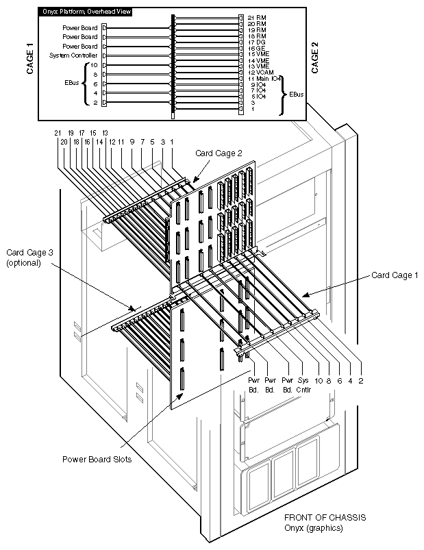
The IRIS ATM board requires one short mezzanine slot on an IO4 board. This section describes how to select an appropriate slot for each IRIS ATM board.
| Caution: This equipment is extremely sensitive and susceptible to damage by electrostatic discharge (ESD), a spark caused by the buildup of electrical static potential on clothing and other material. You must use proper ESD preventive measures as explained in the "Safety" section of the CHALLENGE/Onyx XL Rackmount Installation Instructions. |
Locate the IO4 boards that are currently installed. Slot 11 always has an IO4 board. (See Figure 2-19 for an illustration of the slots.) In addition, slots 9, 7, and/or 5, may contain IO4 boards. An Onyx Rackmount may have one to four IO4 boards installed. Each IO4 board has two mezzanine slots, as illustrated in Figure 2-20. The ATM board may be installed on any of the available mezzanine slots, as detailed below:
If the system has only one IO4 board, this is the location for the IRIS ATM board. The ATM board may be installed in either the upper or lower position on the IO4 board, as illustrated in Figure 2-20.
If the system has more than one IO4 board, you may select any unoccupied mezzanine slot.
If there are no unoccupied mezzanine slots, you must install another IO4 board. Contact the sales representative to order one. The installation cannot be continued until a mezzanine slot is available.
Note: The maximum number of IO4 boards for an Onyx Rackmount system is four. If four IO4 boards are already installed, and if all the mezzanine slots are occupied, IRIS ATM cannot be installed onto this system.
Follow the steps below to install the IRIS ATM board.
Remove the IO4 board that you have selected from the Onyx chassis.
Lay the board on a flat antistatic surface so that the component side faces up and the SCSI connectors face toward you, as illustrated in Figure 2-21.
Locate the selected mezzanine slot (upper or lower) and remove the four screws from the standoffs, as illustrated in Figure 2-21. If the screws are missing, this is not a problem.
Position the IRIS ATM board onto the selected slot so that the connector on the bottom of the board matches the receptacle on the IO4 board and the standoffs match the ATM board's holes. Figure 2-21 illustrates the correct positioning for the upper and lower slots.
Replace the standoff screws. These screws have a "float" feature, and do not tighten. If necessary, use the screws that are shipped with the IRIS ATM package.
Reinstall the IO4 board into the chassis, as illustrated in Figure 2-22. Push the board firmly into the backplane. If the board has a VCAM board, the VCAM board must also seat into the backplane.
Create an adapter identification for the ATM mezzanine board. The identification has the format F-XX-5 for the lower slot and F-XX-6 for the upper slot, where XX is the slot number where the IO4 board resides. For example, a mezzanine board in the upper position on the main IO4 board located in slot 11 is labelled F-11-6.
From the sheets of labels, remove a small-sized label with the identification created in the previous step. Attach the label to the outside of the ATM I/O panel plate that is attached to the internal cable assembly (illustrated in Figure 2-23).
Follow the steps below to attach the internal ATM cables to the ATM board and the panel plate to the card cage's I/O panel.
| Caution: Do not touch the fiber optic material exposed at the ends of the cable. Do not leave the cable ends uncapped. Performance of the fiber optic cable can seriously degrade due to grease or dust. |
Locate the internal cable assembly that consists of two fiber optic lines terminated inside an SC connector at one end and a MIC receptable attached to the ATM I/O panel plate at the other end, as illustrated in Figure 2-23.
| Note: For installations with multiple IRIS ATM boards, replace the single-port panel plate on the cable assembly with the 2-port panel plate that is shipped with the product. |
Remove one blank panel plate from the system's I/O panel and install the ATM panel plate.
Remove the protective caps from the SC connector.
Slide the SC connector into the ATM board's fiber optic receptacle. To ensure proper orientation, the SC plug has guide ridges that must slide into slots in the receptacle.
Close the I/O door and the chassis door.
The ATM connector provided at the ATM IO panel plate is a female, S-type MIC connector. The site's ATM cable for this connection must be multi-mode fiber optic cable terminated with a male MIC connector (S-, A-, and B-types are all compatible).
Remove the protective cap from the port on the ATM panel plate and attach the site's fiber optic cable to the system's ATM panel plate, as illustrated in Figure 2-24. The connection should snap (or click) into place.
| Note: MIC connectors are "keyed" so that they snap into place only when appropriate types are being connected and correct positioning is being used. If the connection does not snap into place, try a different position. If that does not solve the problem verify that the MIC has been designed to mate with an S-type receptacle. |
To finish the installation, do the following:
Flip the circuit breaker on the back of the chassis to ON, then turn the key switch on the front to ON.
When the console prompts you with the question Automatically reconfigure the operating system?, answer yes or y in order to build a new kernel.
Note: If this prompt does not appear, you probably have not installed the IRIS ATM software. Instead of proceeding with the steps below, follow the instructions in the IRIS ATM Release Notes to install and configure the software. Logon and reboot (this is the second time this system is being started) to begin using the newly built operating system. The command lines below can be used to accomplish this step:
% su
Password: thepassword
# reboot
Logon and invoke hinv to verify that the IRIS ATM hardware is listed:
% /sbin/hinv
. . .
ATM OC-3c unit#: slot#, adapter#
where unit# reflects the current setting of the board's Unit Jumper Set or the unit number assigned by the driver (depending on the assignment mode configured in the /var/sysgen/master.d/atm file), slot# indicates the slot in which the IO4 board resides, and adapter# (IO4 adapter) indicates the mezzanine position where the ATM board resides.
Note: If the board is not listed, either (1) the system is running the wrong version of IRIX, (2) the newly installed board's jumpers have the same unit number as one of the ATM boards that are listed, or (3) the board is improperly installed. If no ATM board is listed, use the versions eoe1 command to verify the version of IRIX. If the version is correct or if other IRIS ATM boards are listed, reinstall the product (the board and all cables) making sure to set the jumpers correctly and to seat all the hardware firmly. Follow the instructions in the IRIS ATM Configuration Guide to verify that upper layer applications can send and receive over the ATM subsystem.