This chapter provides an introduction to the IRIS ATM-OC3c for CHALLENGE and Onyx board. For information about the associated protocols (ATM and SONET) and the IRIS ATM software, see the online IRIS ATM Configuration Guide.
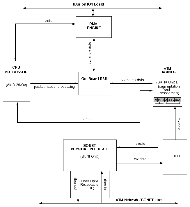
The IRIS ATM-OC3c board supports ATM over SONET OC3c (with a transmission rate of 155.52 megabits per second). Synchronous Optical Network (SONET) is the physical layer protocol. The board is a short (standard) mezzanine board that occupies one position on any IO4 board. The board has a CPU (AMD 29030) send on-board memory to control data processing and TCP and UDP checksumming. Figure 1-1 is a block diagram of the board.
To use the IRIS ATM board, a site must have installed multimode fiber optic cable terminated in MIC connectors. Both 50 and 62.5 micron fiber optic cables are compatible.
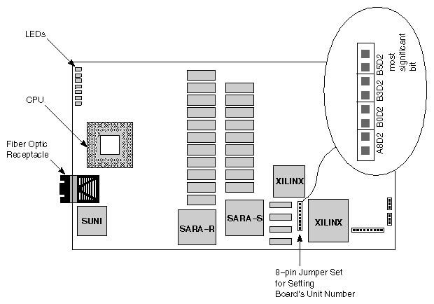
The IRIS ATM board has a number of jumpers; however, the only ones that can be configured are those comprising the 8-pin Unit Jumper Set; these are labeled B5D2, B3D2, B0D2, and A8D2. The location of the Unit Jumper Set is illustrated in Figure 1-2.
Each pair of pins within the Unit Jumper Set configures one bit of the board's 4-bit unit number. The pair of pins labeled B5D2 controls the setting for the most significant bit (for example, for the binary unit number 1000, the B5D2 pins set the 1).
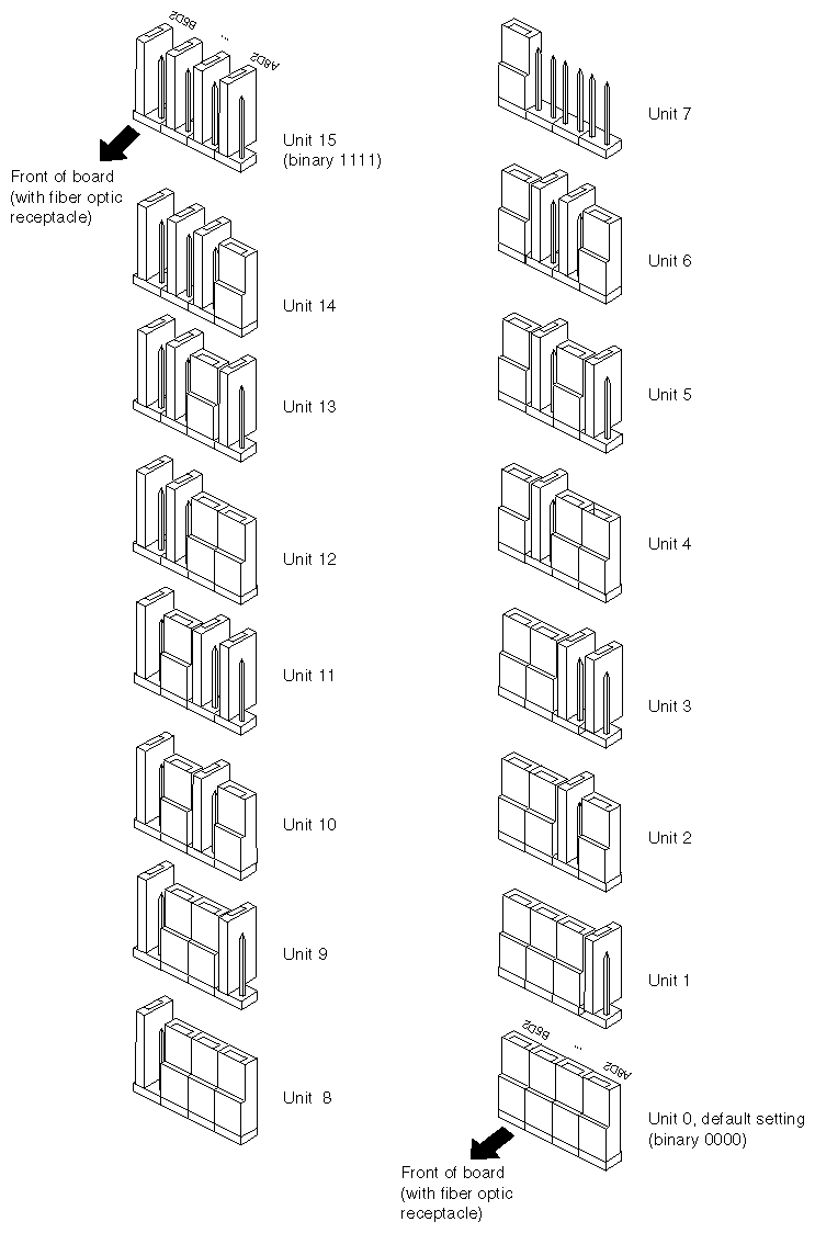
Installing a jumper over 2 pins sets the associated bit to 0. When 2 pins are open (not jumpered), the associated bit is 1.
When the IRIS ATM board is shipped, all the pins of the Unit Jumper Set are jumpered; this configuration sets 0000 binary (which is displayed by /sbin/hinv as ATM unit 0). When more than one IRIS ATM board is installed in a system, you must decide whether to have the boards numbered by the software (the default) or by the jumpers on each board. The /var/sysgen/master.d/atm file controls which of these numbering modes is used. The default is dynamic unit assignment by the software; in this mode, installed boards are assigned sequential numbers according to the order the boards are located during power on. For example, the first board that is found is assigned unit 0 and the second is assigned unit 1. The advantages and disadvantages of these two modes is described in the online IRIS ATM Configuration Guide.
If you decide to have unit numbers assigned by the jumpers, you must edit the /var/sysgen/master.d/atm file, as described in the IRIS ATM Configuration Guide, and change each board's Unit Jumper Set to a unique unit number. Figure 1-3 illustrates how to the set the jumpers for 16 different unit numbers. In this illustration, jumpers that are illustrated at a right-angle to the line of pins, are stored in the unjumpered position, which is binary 1.
Use the following guidelines to select a proper unit identification number for each board:
For the first or only IRIS ATM board in the system, verify that the jumpers are all jumpered, so that the unit number is set to 0.
For each additional IRIS ATM board, assign the next available unit number. Tag each board with its assigned unit number, then, follow the examples in Figure 1-3 to alter the jumpers on each board.
If the system currently has no IRIS ATM board installed, tag the first board as unit 0, the next as unit 1, and so on.
If the system already has one or more IRIS ATM boards installed, use /sbin/hinv to list the current unit numbers for the installed IRIS ATM boards. Then, assign an unused unit number to each new board.
 | Note: If two or more installed boards have the same unit number and if the IRIS ATM driver is configured to read the unit numbers from the jumpers, the first board that is located with the unit number is initialized and brought into operation, but the duplicates are not. When the system encounters each duplicate board, it prints an error message, then skips the board without initializing it. The command /sbin/hinv does not list uninitialized boards, and they do not have device files in the /dev directory. Other installed IRIS ATM boards with unique unit numbers are not affected by this procedure; they will power-on, initialize, and start functioning. |
The IRIS ATM product manages virtual channel (VC) transmission rates by configuring (and reconfiguring) the rate queues and divisors on the ATM-OC3c board. This section describes how VC transmission rates work. The online IRIS ATM Configuration Guide lists the supported rates, which range from 0 to 135,991,460 bits–per–second of user (upper–layer) payload.
Each IRIS ATM-OC3c board has 8 rate queues organized as 2 banks: a0-a3 and b0-b3. These queues are illustrated on the block diagram, Figure 1-1. The "a" bank consists of 4 high-priority queues that are designed for constant bit rate traffic (CBR and VBR channels). The other bank contains 4 low-priority queues that are only used for best effort traffic. High-priority queues are serviced before low-priority ones. As long as there is data awaiting transfer on any high-priority queue, low-priority data is not transmitted. This means that, for applications with a constant flow of data, only queues a0-a3 will ever operate.
Each queue can support one peak rate and 63 different sustainable rates. A peak rate (for CBR, VBR, or best-effort traffic) is the rate at which the rate queue is configured. A sustainable rate (for VBR traffic) is the peak rate divided by a divisor. To set the sustainable transmission rate for a particular VC, the IRIS ATM driver divides one of the board's configured rates by a divisor (ranging between 2 and 64). For example, a rate queue configured for a peak rate of 2000 can support the following sustainable rates (among others): 1000, 666.667, 500, and 40; it cannot support a sustainable rate of 5 (because 2000/64 is greater than 5).
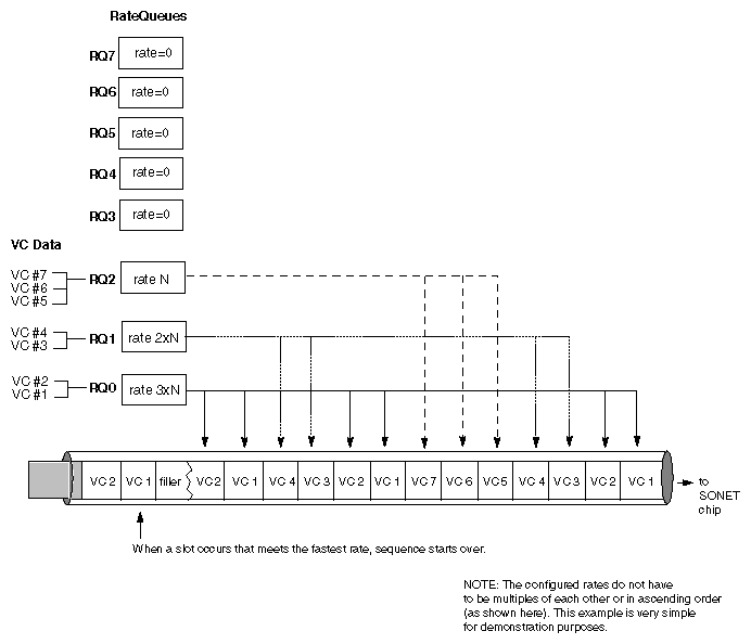
To summarize, the IRIS ATM-OC3c board simultaneously makes available for selection up to 8 different peak rates and up to 504 (8*63) sustainable rates. Multiple virtual channels (VCs) can use a single configured rate, as illustrated in Figure 1-4; all the VCs using that particular queue must have the same peak rate, but they can have different sustainable rates. The rate queues can be reconfigured during operation, as explained in Section 1.3.2, "How IRIS ATM Manages the Transmission Rates." Not all of the available rates on a board can be actively used simultaneously, since this would exceed the board's bandwidth, as explained in Section 1.3.3, "Oversubscription."
During startup, the IRIS ATM driver configures each rate queue with either a default setting (summarized in Table 1-1) or with a value read from the /var/atm/atmhw.conf file. Then, during operation, the driver reconfigures the queues to meet VC rate requests, to respond to atmconfig rate configuration requests, and to respond to application programming interface rate configuration requests. The IRIS ATM driver manages the rate queues as explained below:
The driver considers some queues as locked at a fixed rate and, after the initial configuration at startup, does not change the rates on these queues. This ensures that site-specified rates are always available, even when the queues are not actively being used. The following actions cause a queue to become locked:
any queues that, during startup, are specified in the /var/atm/atmhw.conf file
any queues that, during operation, are configured to a non-zero value by the atmconfig command or by a customer-developed application through the IRIS ATM application programming interface
The driver considers all other queues as unlocked and available for reconfiguration. If a requested VC rate does not exist, the driver searches for an unlocked queue that does not currently have a VC associated with it, and the driver reconfigures the queue to the requested peak rate.
During operation, as VCs are created, the driver associates each newly created VC with the queue whose transmission rate best matches the peak rate requested for that VC. For each request to open a new VC, the driver looks for a queue whose transmission rate best matches the rate requested in the call, following the guidelines explained below:
For VCs carrying best-effort traffic, the driver uses the low-priority queue whose rate is closest to, but slower than, the requested peak rate. If necessary and if possible, the driver reconfigures a rate queue to meet this request.
For VCs carrying CBR and VBR traffic, the driver uses the high-priority queue whose configured rate exactly matches the requested peak rate. If necessary and if possible, the driver reconfigures a rate queue to meet this request.
Note: There can be dozens of CBR and VBR virtual channels active on a board, but the peak rate for each one must be one of the four rates that are configured on the high-priority queues.
Table 1-1 summarizes the default settings configured for the IRIS ATM-OC3c board's rates during power on. If any queue is specified in the /var/atm/atmhw.conf file, the rate for that queue is fixed at the rate specified in the file; all other queues start out with the default value.
Table 1-1. Default Transmission Rates on ATM-OC3c Queues
Rate Queue |
| Default Cell Rate | Default Bit Rate | Priority / Use |
|---|---|---|---|---|
Number Id | String Id | (in ATM cells per second) | (in user payload bits per second) |
|
0 | a0 | unconfigured | 0 | High / CBR, VBR[a] |
1 | a1 | unconfigured | 0 | High / CBR, VBR |
2 | a2 | unconfigured | 0 | High / CBR, VBR |
3 | a3 | unconfigured | 0 | High / CBR, VBR |
4 | b0 | 26041 | 10000000 | Low / BE |
5 | b1 | 78125 | 30000000 | Low / BE |
6 | b2 | 178571 | 68000000 | Low / BE |
7 | b3 | 357142 | 135991460 | Low / BE |
[a] CBR = constant bit rate; VBR = variable bit rate; BE = best effort | ||||
A board is oversubscribed when it is servicing VCs that demand more bandwidth than the board can deliver. This occurs when the sum of all the open VCs multiplied times their average rates is greater than the board's total payload bandwidth.[1] (For best-effort and CBR VCs, the peak rate is used for the average; for VBR VCs, the sustainable rate is used.) The IRIS ATM software contains a number of features that prevent performance degradation due to oversubscription. Whenever there is even one VC open for a CBR traffic contract, the IRIS ATM software refuses to create new VCs once the board's total bandwidth is allocated to open VCs (including the best-effort ones). If all the VCs on a board are best–effort (regardless of which queues they are using), the IRIS ATM software allows the board to become oversubscribed and handles the transmissions in the best manner possible.
| Note: The default TCP/IP configuration uses the maximum bandwidth for any connection. Therefore, a single TCP/IP connection can oversubscribe the port and prevent CBR traffic. To prevent this, there are two options: (1) reduce the default TCP/IP bandwidth (for example, by editing the /var/atm/ifatm.conf file) or (2) use ifconfig to disable the TCP/IP logical network interfaces. |
[1] Total OC3 bandwidth is 155.52 megabits per second; however, of this total, only 135,991,460 is available for user data, which is referred to as the payload bandwidth.