This chapter describes the following advanced topics:
The MPK configuration file loader allows the specification of a preprocessor through the use of the MPK_PARSER_CMD environment variable. The preprocessor command will be invoked with the configuration file name as the first argument, and its output will be parsed by the normal MPK loader. Therefore, the output of this preprocessor has to be an MPK configuration file. For example, the C preprocessor can be used to put different configurations in one ASCII file and to select one using the #define functionality.
The MPK configuration file loader is using only MPK's exposed C functional interface. Therefore, it is possible to create configurations programmatically or even write an alternate parser. The function in Example 5-1 creates a simple one-window configuration.
Example 5-1. Creating a Configuration Programmatically
MPKConfig *createSimpleConfig( void )
{
    // new config
    MPKConfig *config = mpkConfigNew();
    mpkConfigSetName( config, “1-window” );

    // one pipe
    MPKPipe *p = mpkPipeNew();
    mpkConfigAddPipe( config, p );
    mpkPipeSetName( p, “pipe” );

    // one window with viewport [0.25, 0.25,0.5,0.5]
    MPKWindow *w = mpkWindowNew();
    mpkPipeAddWindow( p, w );
    mpkWindowSetName( w, “MPK: simple” );
    float vp[4] = { 0.25, 0.25, 0.5, 0.5 };
    mpkWindowSetViewport( w, vp );

    // one channel
    MPKChannel *c = mpkChannelNew();
    mpkWindowAddChannel( w, c );
    mpkChannelSetName( c, “channel” );
    vp[0]=0.0; vp[1]=0.0; vp[2]=1.0; vp[3]=1.0;
    mpkChannelSetViewport( c, vp );
    float bl[] = { -.5, -.5, -1},
          br[] = {.5,  -.5, -1},
          tl[] = {-.5, .5, -1};
    mpkChannelSetWall( c, bl, br, tl );

    // mono and stereo monitor characteristics
    mpkPipeSetAttribute( p, MPK_PATTR_STEREO_TYPE, MPK_STEREO_RECT );
}
|
As described in the section “The Rendering Callbacks” in Chapter 2, the idle callback can be used to utilize the idle time in the application thread during the rendering of a frame. The exact idle time depends on a number of conditions—for example, the decomposition mode or the current viewpoint. The function mpkConfigIsIdle() can be used to optimize the usage of this idle time, as shown in Example 5-2.
Example 5-2. A Simple Idle Callback
void configIdle( MPKConfig *config )
{
    while( mpkConfigIsIdle( config ))
    {
        // do some processing
    }
}
|
Note that no data used in the rendering callbacks should be modified in the idle callback.
MPK currently supports two timers, MPK_TIMER_AUTO and MPK_TIMER_FRAME. By default, only the MPK_TIMER_AUTO timer is enabled. Both timers can be enabled and disabled using the functions mpkConfigTimerEnable() and mpkConfigTimerDisable(). MPK timer values are always expressed in milliseconds.
The MPK_TIMER_AUTO timer is used for automatically load-balancing DPLEX compounds. Its duration, determined by MPK, is based on the rendering time of the DPLEX children and cannot be set by the application.
The MPK_TIMER_FRAME timer is used to control the execution time of a MPKConfig frame. When the timer is enabled, mpkConfigTimerGetTime() returns the actual duration of the last MPKConfig frame. The desired minimal duration for the subsequent MPKConfig frames can be set using the function mpkConfigTimerSetTime().
MPK uses a POSIX timer to fire alarms. By default, the signal SIGALRM is used to deliver this signal. The function mpkGlobalSetTimerSignal() may be used to change this signal. When using pthread execution mode, the delivery of the timer signal has to be blocked in all threads, except the application thread. Example 5-3 shows the code used by MPK to block the timer signal in all internally created threads.
Example 5-3. Blocking the Timer Signal
// block timer signal in this thread
if( mpkGlobalGetExecutionMode() == MPK_EXECUTION_PTHREAD )
{
    int signal = mpkGlobalGetTimerSignal();
    sigset_t set;

    sigemptyset ( &set );
    sigaddset( &set, signal );
    pthread_sigmask( SIG_BLOCK, &set, NULL );
}
|
MPK applications are multithreaded and may render several views and versions of the same database due to the latency imposed by some decomposition modes. Given this possibility, some types of application data have to be handled carefully. Within an MPK application, there are typically the following types of data:
Application-only data
Static shared data
Dynamic shared data
Frame data
Application-only data is only used by the application thread. Therefore, no special attention has to be paid when using this kind of data.
Static shared data is initialized before calling mpkConfigInit() and is used afterward only in a read-only fashion. Like application-only data, no special precautions have to be taken.
Dynamic shared data is data modified during run time. Therefore, it has to be allocated using mpkMalloc() or mpkCalloc() to allocate the memory from a shared arena in fork execution mode. If this data is accessed for reading and writing concurrently from several threads, it has to be protected using a mutex.
Frame data is shared data that is characteristic to a specific frame. This can be the viewpoint, the position of dynamic parts in the scene, or lighting characteristics. This data, like dynamic shared data, has to be allocated using mpkMalloc() or mpkCalloc(). Frame data is passed from the application thread (the producer) to the rendering threads (the consumers) through the use of mpkConfigFrame(). MPK stores past frame data and passes it to the rendering callbacks according to the latency to be rendered by this callback. When a frame data pointer is not needed anymore, it is passed to the MPKConfig's free-data callback to be freed by the application. Due to the nature of frame data, mutual exclusion is not necessary. The application thread writes to frame data before passing it to mpkConfigFrame(). After it is passed to MPK, the frame data is only accessed by the rendering threads in a read-only fashion.
Xinerama is an X server extension that presents multiple physical screens managed by an X server as a single logical screen to X client applications. Xinerama does not support this abstraction for applications using OpenGL and GLX. A Xinerama-enabled X server will execute all OpenGL and GLX calls on the first physical pipe.
SGI Xinerama is an enhanced version of Xinerama. SGI Xinerama provides the same functionality but is optimized for use on SGI graphics systems. Subsequent references to Xinerama will refer to SGI Xinerama.
In order to meet the various needs of different applications, MPK provides flexible support for Xinerama-enabled X servers. MPK provides the following features to integrate the Xinerama functionality:
Support for Xinerama-aware windows
Transparent scalability for Xinerama windows
Support for Xinerama full-window overlapping
MPK allows the creation of Xinerama-aware windows. These windows can be specifically created on one of the real pipes of the logical Xinerama screen. Thus, the feature allows OpenGL rendering on this pipe while the system is still running a Xinerama-enabled X server. Such windows are typically used for source channels contributing to a compound.
The window attribute hint MPK_WATTR_HINTS_XINERAMA is used to determine if a window should be created using the Xinerama extension or by bypassing the extension on a Xinerama-enabled X server. If set to true, the default value, the window is created using Xinerama. Otherwise, MPK bypasses Xinerama. This hint has no effect on X servers having the Xinerama extension disabled.
The use of Xinerama-aware windows has some caveats with respect to window handling and the X events that are received for these windows. The following two caveats are noteworthy:
Xinerama-aware windows bypass the window manager—that is, they are not handled at all. The product OpenGL Multipipe supplies a customized version of 4Dwm, which can handle Xinerama-aware windows. See the start_ompwm(1) man page for further details.
Mouse events report their position with respect to the physical pipe as if no Xinerama is used. In contrast, mouse events for Xinerama windows are reported with respect to the logical pipe. Moving the mouse pointer over the window does not necessarly give you the keyboard focus on that window; the keyboard events may go to another window. Mouse events always go to the pointer-defined window.
MPK transparently parallels the rendering for Xinerama windows across the pipes virtualized by Xinerama.
In order to correctly handle the window, the MPKWindow, the X11 and the OpenGL initialization and exit have to be separated. The MPKConfig's window initialization callback initializes the MPKWindow in which the X11 and OpenGL initialization callbacks are set. Likewise, the MPKConfig's exit-window callback does clean up the MPKWindow, and the window X11 and OpenGL exit callbacks are responsible for de-initializing X11 and OpenGL.
MPK supports Xinerama full-window overlapping to provide transparent scalability through the use of an SGI Scalable Graphics Compositor. When Xinerama is used to overlap screen regions on an edge-blended display or compositor-based system, the cursor will seem to disappear when it enters the overlapped or uncomposited regions of the display.
By upgrading to IRIX 6.5.20 or later, you can use an X server feature that prevents the cursor from disappearing in these cases. It causes additional cursor images (not real cursors) to appear on all pipes contributing to the overlapped regions. To enable this feature, add the –phantomcursors flag to the X server command line in the /var/X11/xdm/Xservers file.
For more information about the –phantomcursors option, see the Xsgi(1) man page.
MPK offers native support for compositing hardware. Eliminating the need for pixel transfers and software recomposition, this specialized hardware performs the recomposition part of an MPKCompound.
Currently, MPK provides support for DPLEX option boards and the SGI Scalable Graphics Compositor. MPK handles the setup and control of the hardware by using the GLX_SGIX_hyperpipe API (see the hyperpipe(3) man page). An application written for MPK can immediatly take advantage of this hardware without having to take care of the GLX_SGIX_hyperpipe extension.
The mode flag HW is used to enable the support for DPLEX, EYE, FSAA, and 2D compounds. The mode flag NOCOPY has to be specified to disable the pixel transfer and software recomposition.
MPK provides two data structures to give access to the transported color, depth and stencil values during compound assembly:
MPKFrames for compound children can be retrieved using the function mpkCompoundGetAssemblyFrame() in the pre- and post-assemble callbacks (see the section “Custom Assembly” in Chapter 3).
 | Note: The function mpkFrameDelete() should not be called on MPKFrames acquired using mpkCompoundGetAssemblyFrame(), since these are managed by MPK. |
The format field of an MPKFrame indicates which images it contains. The region defines the fractional viewport covered by this frame with respect to the destination channel.
The individual MPKImages for each MPKFrame can be retrieved using mpkFrameNImages() and mpkFrameGetImage(). For assembly frames, each MPKImage used has a buffer allocated, which holds the pixel data for this MPKImage. The format and type specify the attributes of the pixel data, as described in the man page glDrawPixels(3G). The size of the MPKImage defines the width and height of the pixel data stored in the buffer. The offset specifies the pixel offset with respect to the region of the parent MPKFrame or mpkChannelDrawImage(). If you change one parameter, you must ensure that the other parameters (especially, the allocated buffer) are adjusted accordingly.
The final pixel viewport for one MPKImage is computed as follows:
width = ChannelPixelViewport[2];
height = ChannelPixelViewport[3];

// compute frame's pixel viewport
MPKImagePixelViewport[0] = MPKFrameRegion[0] * width;
MPKImagePixelViewport[1] = MPKFrameRegion[1] * height;

MPKImagePixelViewport[2] = (MPKFrameRegion[0]+MPKFrameRegion[2]) * width;
MPKImagePixelViewport[3] = (MPKFrameRegion[1]+MPKFrameRegion[3]) * height;

MPKImagePixelViewport[2] -= MPKImagePixelViewport[0];
MPKImagePixelViewport[3] -= MPKImagePixelViewport[1];

// clip to image size
if ( MPKImagePixelViewport[2]  > MPKImageSize[0] )
    MPKImagePixelViewport[2] = MPKImageSize[0];
if ( MPKImagePixelViewport[3] > MPKImageSize[1] )
    MPKImagePixelViewport[3] = MPKImageSize[1];

// add image offset
MPKImagePixelViewport[0] += MPKImageOffset[0];
MPKImagePixelViewport[1] += MPKImageOffset[1];
|
Figure 5-1 illustrates a frame and an image within one channel.
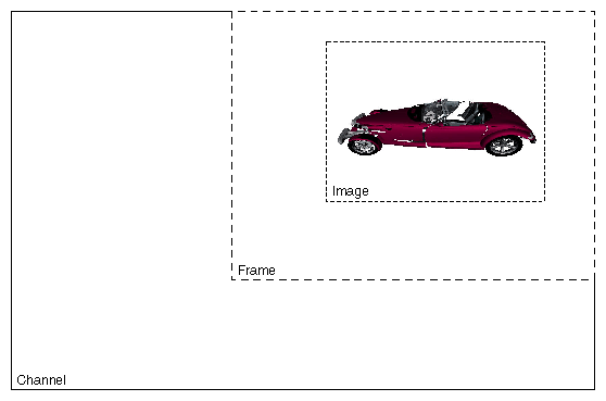
One possible use of this interface is to do software-based composition, as described by the following pseudo code:
void assembleCB( MPKCompound *compound, void *userData )
{
    //====================
    // tile assembly frames :
    //
    // assembly images may have different positions and sizes.
    // Therefore we need to extract tiles in which the number of
    // contributing images is constant. For this we simply sort
    // all input image boundaries into xDim[] and yDim[] vectors,
    // so that
    //
    // tile[i,j] = [ xDim[i], xDim[i+1]-1 ] x [ yDim[j], yDim[j+1]-1 ]

        for each assembly frame
            for each image (color, depth, stencil)

                compute image's xStart, xEnd, yStart, yEnd

                sorted-add xStart, xEnd to xDim vector
                sorted-add yStart, yEnd to yDim vector

            end for
        end for

    //====================
    // allocate output frame and image buffers :
    //
    // the output frame dimensions (ie. frame origin and images size)
    // corresponds to the bounding box of all tiles.
    // Note that we could also allocate a vector of output tiles, and
    // later perform tiled re-composition.
    // Note also that the image buffers must be initialized.

        allocate output frame
        set origin to xDim[0], yDim[0]

        allocate image buffers for output frame
        set output frame images to image buffers
        set size of output images to xDim[n]-xDim[0], yDim[m]-yDim[0]

        initialize image buffer values wrt depth, color, stencil

    //====================
    // compose output frame :
    //
    // loop over all tiles (boundaries), and
    //
    // 1. first setup a vector of flags that is indexed by frame#
    //    and imageType. Each element of the vector indicates whether
    //    the corresponding image contributes to the tile.
    //
    //  2. then we loop over all pixel coordinates within the tile
    //     and compose each assembly frame's pixel value, depending
    //     on the flag for this frame and image type.


        for each tile ( i, j )

            // flag image contributions for this tile

            for each assembly frame
                for each image (color, depth, stencil)

                    compare xStart, yStart with tile boundaries
                    set flag[frame#][imageType] accordingly

                end for
            end for

            if no image used in the tile
                continue
            end if

            // compose all contributing pixels

            for each x  ( xDim[i], ... xDim[i+1]-1 )
                for each y ( yDim[j], ... yDim[j+1]-1 )

                    for each assembly frame
                        for each image (color, depth, stencil)

                            if !flag[frame#][imageType]
                                continue
                            end if

                            compose image.pixel( x, y ) to output
                            frame's corresponding
                            image.pixel( x-xDim[0], y-yDim[0] )

                    end for
                end for

            end for
        end for
}
|
This section describes items to consider when you use MPK in conjunction with the following libraries:
There are several topics to consider when using MPK with OpenGL Volumizer:
For sample code, see the volview application that ships with OpenGL Volumizer. The application is a full volume-viewer application that uses OpenGL Multipipe SDK as the underlying software layer to provide run-time configurability and scalability.
MPK supports the pthread, fork, and sproc multiprocess mechanisms. The following table describes their use with OpenGL Volumizer:
| Mode | Prescribed Use with OpenGL Volumizer | |
| pthread | Works well with OpenGL Volumizer since OpenGL Volumizer is thread-safe. | |
| fork | Works well with OpenGL Volumizer since OpenGL Volumizer is thread-safe. Use the vzMemory class to ensure allocation of OpenGL Volumizer objects from shared memory by using the code shown in Example 5-4. | |
| sproc | Does not work with OpenGL Volumizer since OpenGL Volumizer links against the pthread library. Example 5-4. Using vzMemory to Allocate Objects from Shared Memory |
Ensure that OpenGL Volumizer nodes are stored as part of the shared data for the application. The data should not be replicated across multiple pipes unless there are special needs since volume data tends to be quite big in practice. OpenGL Volumizer render actions manage the graphics resources on a per-pipe basis—that is, they create one render action per MPKWindow. Do not use multiple MPKWindows per MPKPipe since this will lead to inefficient resource management and also force unnecessary context switches. However, this practice might be okay for testing purposes on single-pipe machines.
The following notes are pertinent regarding scalability and stereo:
2D decomposition
Scales fill rate in a straightforward manner. If you can divide the volume data into smaller bricks, you can use view-frustum culling to scale the texture memory size also by moving these bricks in and out of the texture memory of the pipes.DB decomposition
Scales fill rate and texture memory size. Divide the volume data into multiple bricks and render equal number of bricks on each of the pipes. You need to pre-modulate the transfer function (lookup table) before rendering to compensate for the image blending operation used to composite the results together.3D decomposition
Data streaming (3D decomposition) is not supported by OpenGL Volumizer since the order in which the source channels are composited cannot be controlled in this mode. However, true volume decomposition can be achieved using DB decomposition, which enables the application to scale in texture memory by distributing the data across multiple pipes. This technique is illustrated in the volview example.DPLEX decomposition
DPLEX rendering is supported by OpenGL Volumizer. Full-scale software recomposition (that is, where the destination channel is also contributing actively in the rendering) simply requires the application to set the OpenGL Volumizer slice callback appropriately so that mpkChannelSyncDPlex() is invoked after every slice in the rendering thread.
OpenGL Shader integrates seamlessly with OpenGL Multipipe SDK to provide enhanced control of an object's appearance. Use the OpenGL Shader C++ API only when working with MPK. Do not use islc or ipf2ogl in this context.
The main concern in using OpenGL Shader with MPK is the proper use of the OpenGL Shader classes in the multithreaded environment provided by MPK:
All islShader objects should always be maintained by the application. You can do this before initializing MPK, for example.
Create and compile all islAppearance objects from the application thread. Then use one appearance object per window thread, because the shader matrix will be updated while drawing. You can use islCopyAction() to create multiple copies of an appearance object for this purpose.
Compile the islAppearance objects beforehand using islCompileAction() and then copy the compiled appearances.
Remember to update the appearance copies after modifying the original appearance during run time.
For more detailed information about the OpenGL Shader API, refer to the OpenGL Shader documentation.
The critical concern in using Open Inventor with MPK is thread safety. There are currently two versions of Open Inventor, each differing in terms of thread safety:
Open Inventor from SGI
Open Inventor from SGI is not thread-safe. Therefore, applications using this version must use fork execution mode. The example flip.iv uses one Open Inventor scene graph and renderer per window process. This restricts the example to render static scenes but proper event handling could update the scene on each window thread to allow dynamically changing scenery.Open Inventor from TGS
Starting with version 3.0, Open Inventor from TGS is thread-safe. This feature allows the rendering of the same scene graph by multiple threads concurrently. One renderer per window thread can then be used to render the scene graph, which may be transported through frame data, if necessary.
A Motif application is event-driven. Motif has an event loop, from which user-defined callbacks are called. A WorkProc, which is called whenever the application is idle, may be used to achieve a non-event-driven behavior. Instead of having a main loop, such as that in Example 2-13, the application transfers this responsibility to Motif by calling XtAppMainLoop(). Therefore, a new MPKConfigFrame is either triggered directly from the event callbacks or from a WorkProc specified by the function XtAppAddWorkProc(). See the XtAppAddWorkProc(3Xt) man page for more details.
Often libraries and functions that are not thread-safe are used during rendering. The ideal solution, if feasible, is to rework this software to be thread-safe. If that is not possible, the library has to be used in a way that prevents concurrent access of shared data. The following are possibile solutions:
If the functionality is used sparsely, a global lock around all calls to the library may be used. Note that this lock prevents the window threads to use the library concurrently and may lead quickly to scalability problems. Additionally, any software that uses the OpenGL context to store certain information—for example, display lists—cannot be used using this approach.
Depending on the task, it is often the best solution to initialize and use one instance of the given library per window. If the library is using global variables to store certain state information, this approach requires the fork execution mode to separate the address spaces between the window processes.