The 2 Gb TP9100 storage system includes a processor and associated monitoring and control logic that allows it to diagnose problems within the storage system's power, cooling, and drive systems.
SES (SCSI enclosure services) communications are used between the storage system and the RAID controllers. Status information on power, cooling, and thermal conditions is communicated to the controllers and is displayed in the management software interface.
The enclosure services processor is housed in the ESI/ops panel module. The sensors for power, cooling, and thermal conditions are housed within the power supply/cooling modules. Each module in the storage system is monitored independently.
 | Note: For instructions on opening the rear door of the rack, see “Opening and Closing the Rear Rack Door” in Chapter 1. |
This chapter contains the following sections:
RAID stands for “redundant array of independent disks”. In a RAID system multiple disk drives are grouped into arrays. Each array is configured as system drives consisting of one or more disk drives. A small, but important set of guidelines should be followed when connecting devices and configuring them to work with a controller.
Follow these guidelines when configuring a RAID system:
Distribute the disk drives equally among all the drive channels on the controller. This results in better performance. The TP9100 has two drive channels.
A drive pack can contain a maximum of 16 drives.
A drive pack can contain drives that are on any drive channel.
If configuring an online spare disk drive, ensure that the spare disk drive capacity is greater than or equal to the capacity of the largest disk drive in all redundant drive packs.
When replacing a failed disk drive, ensure that the replacement disk drive capacity is greater than or equal to the capacity of the failed disk drive in the affected drive pack.
If cords are missing or damaged, plugs are incorrect, or cables are too short, contact your supplier for a replacement.
If the alarm sounds when you power on the storage system, one of the following conditions exists:
A fan is slowing down. See “Power Supply/Cooling Module LEDs” for further checks to perform.
Voltage is out of range. The tower requires 115/220 Volts (autoranging), and the rack requires 200-240 Volts (autoranging).
There is an overtemperature or thermal overrun condition. See “Solving Storage System Temperature Issues”.
There is a storage system fault. See “ESI/Ops Panel LEDs and Switches”.
There are mixed single-port and dual-ports modules within an enclosure. Only one type of module may be installed in an enclosure.
If the SGI server does not recognize the storage system, check the following:
Ensure that the device driver for the host bus adapter board has been installed. If the HBA was installed at the factory, this software is in place; if not, check the HBA and the server documentation for information on the device driver.
Ensure the FC-AL interface cables from the LRC I/O module to the Fibre Channel board in the host computer are installed correctly.
Check the selector switches on the ops panels of the storage system as follows:
On a tower or a RAID enclosure the ops panel should be set to address 1.
On the first expansion enclosure attached to a RAID system, the ops panel should be set to address 2.
On the first enclosure in a JBOD system, the ops panel should be set to address 1. Other enclosures that are daisy chained to the first enclosure should be addressed sequentially (2-7).
Ensure that the LEDs on all installed drive carrier modules are green. Note that the drive LEDs flash during drive spinup.
Check that all drive carrier modules are correctly installed.
If an amber disk drive module LED drive fault is on, there is a drive fault. See Table 5-7.
If the SGI server connected to the storage system is reporting multiple Hard Error (SCS_DATA_UNDERRUN) errors in the /var/adm/SYSLOG, the cabling connected to the controller reporting the errors requires cleaning or replacement. For more information on cleaning cables, refer to “Care and Cleaning of Optical Cables”.
This section summarizes LED functions and gives instructions for solving storage system problems in these subsections:
Figure 5-1 shows details of the ESI/ops panel .
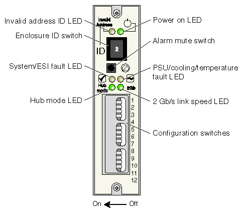
Table 5-1 summarizes functions of the LEDs on the ESI/ops panel
LED | Description | Corrective Action |
|---|---|---|
Power on | This LED illuminates green when power is applied to the enclosure. | N/A |
Invalid address | This LED flashes amber when the enclosure is set to an invalid address mode. | Change the enclosure address thumb wheel to the proper setting. If the problem persists, contact your service provider. |
System/ESI fault | This LED illuminates amber and the audible alarm sounds when the ESI processor detects an internal problem. This LED flashes when an over- or under-temperature condition exists. | Contact your service provider. |
PSU/cooling/ | This LED illuminates amber if an over- or under-temperature condition exists. This LED flashes if there is an ESI communications failure. | Check for proper airflow clearances and remove any obstructions. If the problem persists, lower the ambient temperature. In case of ESI communications failure, contact your service provider. |
Hub mode | This LED illuminates green when the host side switch is enabled (RAID only). | N/A |
2-Gb link speed | This LED illuminates green when 2-Gb link speed is detected. | N/A |
The Ops panel switch settings for a JBOD enclosure are listed in Table 5-2. The ops panel switch settings for a RAID enclosure are listed in Table 5-3. The switches are read only during the power-on cycle.
Table 5-2. Ops Panel Configuration Switch Settings for JBOD
Switch | Function | Function When Off |
| Function When On |
|---|---|---|---|---|
1 (On[a]) | Loop select single (1x16) or dual (2x8) | LRC operates as 2 loops of 8 drives (2x8). Refer to drive addressing mode 2. |
| LRC operates as 1 loop of 16 drives |
2 (On) | Loop terminate mode | If no signal is present on external FC port, the loop is left open |
| If no signal is present on external FC port, then the loop is closed |
3 (Off)[b] | N/A | N/A |
| N/A |
4 (Off) | N/A | N/A |
| N/A |
5 and 6 | RAID host hub speed select Used only for RAID configurations. | Sw 5 | Sw 6 | Function |
|
| Off | Off | Force 1 Gb/s |
|
| On | Off | Force 2 Gb/s |
|
| Off | On | Reserved |
|
| On | On | Auto loop speed detect based on LRC port signals |
7 and 8 | Drive loop speed select | Sw 7 | Sw 8 | Function |
|
| Off | Off | Force 1 Gb/s |
|
| On | Off | Force 2 Gb/s |
|
| Off | On | Speed selected by EEPROM bit |
|
| On | On | Auto loop speed detect based on LRC port signals |
9 and 10 | Drive addressing mode | Sw 9 | Sw 10 | Function |
|
| On | On | Mode 0 - Single loop, base 16, offset of 4, |
|
| Off | On | Mode 1 - Single loop, base 20, 6 address ranges |
|
| On[d] | Off | Mode 2 - JBOD, dual loop, base 8, |
|
| Off | Off | Mode 3 (Not used) |
11 (On) | Soft select | Selects switch values stored in EEPROM |
| Selects switch values from hardware switches |
12 (Off) | Not used | Not used |
| Not used |
[a] Bolded entries indicate default switch settings for a 1X16 JBOD. Set switches 1 and 10 to Off for 2X8 JBOD. [b] Switches 3, 5, and 6 are used in RAID configurations [c] Mode 0 (switches 9 and 10 set to On) is the SGI default factory setting [d] Selecting mode 2 forces 2x8 dual loop selection | ||||
Table 5-3. Ops Panel Configuration Switch Settings for RAID
Switch Number | Function | Function when Off |
| Function when On |
|---|---|---|---|---|
1 (On[a]) | Loop select single (1x16) or dual (2x8) | LRC operates as two loops of 8 drives |
| LRC operates as 1 loop of 16 drives |
2 (On) | Loop terminate mode | If no signal is present on the external FC port, then the loop is left open |
| If no signal is present on the external FC port then the loop is closed internally |
3 (Off) | Hub mode select | Hub ports connect independently |
| RAID host FC ports are linked together internally |
4 (Off) | Not used. |
|
|
|
5 and 6 | RAID host hub speed select Note: Set switches 5 and 6 to Off to force 1 Gb/s if connecting RAID controllers to 1-Gb/s HBAs or switches | Sw 5 | Sw 6 | Function |
|
| Off | Off | Force 1 Gb/s |
|
| On | Off | Force 2 Gb/s |
|
| Off | On | Reserved |
|
| On | On | Auto loop speed detect based on LRC port signals |
7 and 8 | Drive loop speed select | Sw 7 | Sw 8 | Function |
|
| Off | Off | Force 1 Gb/s |
|
| On | Off | Force 2 Gb/s |
|
| Off | On | Speed selected by EEPROM bit |
|
| On | On | Auto loop speed detect based on LRC port signals |
9 and 10 | Drive addressing mode | Sw 9 | Sw 10 | Function |
|
| On | On | Mode 0 - Single loop, base 16, offset of 4, |
|
| Off | On | Mode 1 - Single loop, base 20, 6 address ranges |
|
| On | Off | Mode 2 - JBOD, dual loop, base 8, |
|
| Off | Off | Mode 3 (Not used) |
11 (On) | Soft select | Selects switch values stored in EEPROM |
| Selects switch values from hardware switches |
12 (Off) | Not used | Not used |
| Not used |
[a] Bolded entries indicate SGI's default switch settings for RAID [b] Mode 0 (switches 9 and 10 set to On) is the SGI default factory setting [c] Mode 2 (2x8) is not supported in a RAID configuration | ||||
Note the following:
If all LEDs on the ESI/ops panel flash simultaneously, see “Using Test Mode ”.
If test mode has been enabled (see “Using Test Mode ”), the amber and green drive bay LEDs flash for any non-muted fault condition.
Figure 5-2 shows the meanings of the LEDs on the power supply/cooling module.
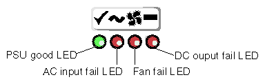
If the green “PSU good” LED is not lit during operation, or if the power/cooling LED on the ESI/ops panel is amber and the alarm is sounding, contact your service provider.
Figure 5-3 shows the LEDs on the dual-port RAID LRC I/O module.
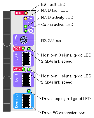
Table 5-4 explains what the LEDs in Figure 5-3 indicate.
Table 5-4. Dual-port RAID LRC I/O Module LEDs
LED | Description | Corrective Action |
|---|---|---|
ESI fault | This LED illuminates amber and the audible alarm sounds when the ESI processor detects an internal problem. | Check for mixed single-port and dual-port modules within an enclosure. Also check the drive carrier modules and PSU/cooling modules for faults. If the problem persists, contact your service provider. |
RAID fault | This LED illuminates amber when a problem with the RAID controller is detected. | Contact your service provider. |
RAID activity | This LED flashes green when the RAID controller is active. | N/A |
Cache active | This LED flashes green when data is read into the cache. | N/A |
Host port signal good (1 and 2) | This LED illuminates green when the port is connected to a host. | Check both ends of the cable and ensure that they are properly seated. If the problem persists, contact your service provider. |
Drive loop signal good | This LED illuminates green when the expansion port is connected to an expansion enclosure. | Check both ends of the cable and ensure that they are properly seated. If the problem persists, contact your service provider. |
Figure 5-4 shows the LEDs on the single-port RAID LRC I/O module.
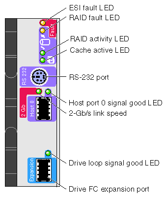
Table 5-5 explains what the LEDs in Figure 5-4 indicate.
Table 5-5. Single-port RAID LRC I/O Module LEDs
LED | Description | Corrective Action |
|---|---|---|
ESI fault | This LED illuminates amber and the audible alarm sounds when the ESI processor detects an internal problem. | Check the drive carrier modules and PSU/cooling modules. If the problem persists, contact your service provider. |
RAID fault | This LED illuminates amber when a problem with the RAID controller is detected. | Contact your service provider. |
RAID activity | This LED flashes green when the RAID controller is active. | N/A |
Cache active | This LED flashes green when data is read into the cache. | N/A |
Host port signal good | This LED illuminates green when the port is connected to a host. | Check both ends of the cable and ensure that they are properly seated. If the problem persists, contact your service provider. |
Drive loop signal good | This LED illuminates green when the expansion port is connected to an expansion enclosure. | Check both ends of the cable and ensure that they are properly seated. If the problem persists, contact your service provider. |
The LEDs on the rear of the RAID loopback LRC I/O module function similarly to those on the RAID LRC I/O modules. See “RAID LRC I/O Module LEDs” for more information.
Figure 5-5 shows the JBOD LRC I/O module LEDs.
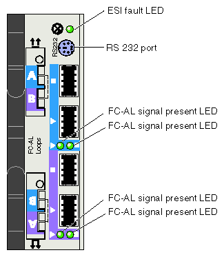
Table 5-6 explain what the LEDs in Figure 5-5 indicate.
Table 5-6. JBOD LRC I/O Module LEDs
LED | Description | Corrective Action |
|---|---|---|
ESI fault | This LED illuminates amber and the audible alarm sounds when the ESI processor detects an internal problem. | Check the drive carrier modules and PSU/cooling modules. If the problem persists, contact your service provider. |
FC-AL signal present | These LEDs illuminate green when the port is connected to an FC-AL. | Check the cable connections. If the problem persists, contact your service provider. |
Each disk drive module has two LEDs, an upper (green) and a lower (amber), as shown in Figure 5-6.
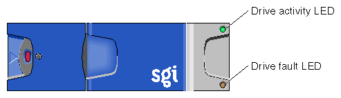
Table 5-7 explains what the LEDs in Figure 5-6 indicate.
Table 5-7. Disk Drive LED Function
Green LED | Amber LED | State | Remedy |
|---|---|---|---|
Off | Off | Disk drive not connected; the drive is not fully seated. | Check that the drive is fully seated |
On | Off | Disk drive power is on, but the drive is not active. | N/A |
Blinking | Off | Disk drive is active. | N/A |
Flashing at 2-second intervals | On | Disk drive fault (SES function). | Contact your service provider for a replacement drive and follow instructions in Chapter 6, “Installing and Replacing Drive Carrier Modules” . |
N/A | Flashing at half-second intervals | Disk drive identify (SES function). | N/A |
In addition, the amber drive LED on the ESI/ops panel alternates between on and off every 10 seconds when a drive fault is present.
The ESI/ops panel includes an audible alarm that indicates when a fault state is present. The following conditions activate the audible alarm:
You can mute the audible alarm by pressing the alarm mute button for about a second, until you hear a double beep. The mute button is beneath the indicators on the ESI/ops panel (see Figure 5-1).
When the alarm is muted, it continues to sound with short intermittent beeps to indicate that a problem still exists. It is silenced when all problems are cleared.
| Note: If a new fault condition is detected, the alarm mute is disabled. |
This section explains storage system temperature conditions and problems in these subsections:
The storage system uses extensive thermal monitoring and ensures that component temperatures are kept low and acoustic noise is minimized. Airflow is from front to rear of the storage system. Dummy modules for unoccupied bays in enclosures and blanking panels for unoccupied bays in the rack must be in place for proper operation.
If the ambient air is cool (below 25 °C or 77 °F) and you can hear that the fans have sped up by their noise level and tone, then some restriction on airflow might be raising the storage system's internal temperature. The first stage in the thermal control process is for the fans to automatically increase in speed when a thermal threshold is reached. This might be a normal reaction to higher ambient temperatures in the local environment. The thermal threshold changes according to the number of drives and power supplies fitted.
If fans are speeding up, follow these steps:
Check that there is clear, uninterrupted airflow at the front and rear of the storage system.
Check for restrictions due to dust buildup; clean as appropriate.
Check for excessive recirculation of heated air from the rear of the storage system to the front.
Check that all blank plates and dummy disk drives are in place.
Reduce the ambient temperature.
The four types of thermal alarms and the associated corrective actions are described in Table 5-8.
Alarm Type | Indicators | Solutions |
|---|---|---|
High temp warning | Audible alarm sounds Ops panel system fault LED flashes Fans run at higher speed than normal SES temperature status is non-critical PSU Fault led is lit | If possible, power down the enclosure; then check the following:
|
High temp failure | Audible alarm sounds Ops panel system fault LED flashes Fans run at higher speed than normal SES temperature status is critical PSU Fault led is lit |
|
Low temp warning | Audible alarm sounds Ops panel system fault is lit SES temperature status is non-critical |
|
Low temp failure | Audible alarm sounds Ops panel system fault is lit SES temperature status is critical |
|
When no faults are present in the storage system, you can run test mode to check the LEDs and the audible alarm on the ESI/ops panel. In this mode, the amber and green LEDs on each of the drive carrier modules and the ESI/ops panel flash on and off in sequence; the alarm beeps twice when test mode is entered and exited.
To activate test mode, press the alarm mute button until you hear a double beep. The LEDs then flash until the storage system is reset, either when you press the alarm mute button again or if an actual fault occurs.
 | Warning: Never look into the end of a fiber optic cable to confirm that light is being emitted (or for any other reason). Most fiber optic laser wavelengths (1300 nm and 1550 nm) are invisible to the eye and cause permanent eye damage. Shorter wavelength lasers (for example, 780 nm) are visible and can cause significant eye damage. Use only an optical power meter to verify light output. |
| Warning: Never look into the end of a fiber optic cable on a powered device with any type of magnifying device, such as a microscope, eye loupe, or magnifying glass. Such activity can cause a permanent burn on the retina of the eye. Optical signal cannot be determined by looking into the fiber end. |
Fiber optic cable connectors must be kept clean to ensure long life and to minimize transmission loss at the connection points. When the cables are not in use, replace the caps to prevent deposits and films from adhering to the fiber. A single dust particle caught between two connectors will cause significant signal loss. In addition to causing signal loss, dust particles can scratch the polished fiber end, resulting in permanent damage. Do not touch the connector end or the ferrules; your fingers will leave an oily deposit on the fiber. Do not allow uncapped connectors to rest on the floor.
If a fiber connector becomes visibly dirty or exhibits high signal loss, carefully clean the entire ferrule and end face with special lint-free pads and isopropyl alcohol. The end face in a bulkhead adapter on test equipment can also be cleaned with special lint-free swabs and isopropyl alcohol. In extreme cases, a test unit may need to be returned to the factory for a more thorough cleaning.
Never use cotton, paper, or solvents to clean fiber optic connectors; these materials may leave behind particles or residues. Instead, use a fiber optic cleaning kit especially made for cleaning optical connectors, and follow the directions. Some kits come with canned air to blow any dust out of the bulkhead adapters. Be cautious, as canned air can damage the fiber if not used properly. Always follow the directions that come with the cleaning kit.