This chapter explains the operation of the RAID controller in the following sections:
Two software components allow you to manage the RAID controllers: the RAID controller firmware and the RAID management software.
RAID firmware has the following characteristics:
Resides on RAID controller (FFX-2) in the LRC I/O module.
Controls the low-level hardware functions.
Controls RAID functionality.
Can be upgraded or “flashed” in the field by trained service personnel.
RAID management software (TPM) has the following characteristics:
Resides on the host system.
Use in-band management to interface firmware.
Provides a graphical user interface (GUI).
RAID stands for “redundant array of inexpensive disks.” In a RAID storage system, multiple disk drives are grouped into arrays. Each array is configured as a single system drive consisting of one or more disk drives.
Correct installation of the disk array and the controller requires a proper understanding of RAID technology and concepts. The controllers implement several versions of the Berkeley RAID technology, as summarized in Table 4-1.
 | Note: Although JBOD (“just a bunch of disks”) is not strictly a RAID level, it is included at various points in this discussion for comparison to RAID levels. It is sometimes referred to as RAID 7. |
Table 4-1. Supported RAID Levels
You must select an appropriate RAID level when you define or create system drives. This decision is based on how you prioritize the following:
Disk capacity utilization (number of disk drives)
Data redundancy (fault tolerance)
Disk performance
The controllers make the RAID implementation and the disk drives' physical configuration transparent to the host operating system. This transparency means that the host operating logical drivers and software utilities are unchanged, regardless of the RAID level selected.
Although a system drive may have only one RAID level, RAID levels can be mixed within a drive pack (LUN), as illustrated in Figure 4-1.

In Figure 4-1, the smaller system drive (B0) is assigned a RAID 5 level of operation, while the larger system drive (B1) is assigned a RAID 0+1 level of operation.
Remember that different RAID levels exhibit different performance characteristics for a particular application or environment. The controller affords complete versatility in this regard by allowing multiple RAID levels to be assigned to a drive pack.
Drives are fault-tolerant when you use a RAID level providing redundancy. In the simplex configuration, however, if the controller or host bus adapter fails, the data is not accessible until the failure is corrected.
Capacity, availability, and performance are three benefits, collectively known as CAP, that should characterize your expectations of the disk array subsystem.
It is impossible to configure an array optimizing all of these characteristics; that is a limitation of the technology. For example, maximum capacity and maximum availability cannot exist in a single array. Some of the disk drives must be used for redundancy, which reduces capacity. Similarly, configuring a single array for both maximum availability and maximum performance is not an option.
The best approach is to prioritize requirements. Decide which benefit is most important for the operating environment. The controller in the 2 Gb TP9100 storage system is versatile enough to offer any of these preferences, either singly or in the most favorable combination possible.
The three benefits are further explained in these subsections:
Table 4-2 shows the relationship between RAID levels and effective capacities offered for the quantity X disk drives of N capacity. As an example, it provides computed capacities for six 2-GB disk drives.
Table 4-2. RAID Level Maximum Capacity
RAID Level | Effective Capacity | Example: Capacity in GB |
|---|---|---|
X*N | 6*2 = 12 | |
(X*N)/2 | 6*2/2 = 6 | |
(X-1)*N | (6-1)*2 = 10 | |
(X-1)*N | (6-1)*2 = 10 | |
(X*N)/2 | (6*2)/2 = 6 | |
X*N | 6*2 = 12 |
The greatest capacities are provided by RAID 0 and JBOD, with the entire capacity of all disk drives being used. Unfortunately, with these two solutions, there is no fault tolerance. RAID 3 and RAID 5 give the next best capacity, followed by RAID 1 and RAID 0+1.
Table 4-3 presents definitions of array operating conditions.
Table 4-3. Array Operating Conditions
Array Condition | Meaning |
|---|---|
Normal (online) | The array is operating in a fault-tolerant mode, and can sustain a disk drive failure without data loss. |
Critical | The array is functioning and all data is available, but the array cannot sustain a second disk drive failure without potential data loss. |
Degraded | The array is functioning and all data is available, but the array cannot sustain a second disk drive failure without potential data loss. Additionally, a reconstruction or rebuild operation is occurring, reducing the performance of the array. The rebuild operation takes the array from a critical condition to a normal condition. |
Offline | The array is not functioning. If the array is configured with a redundant RAID level, two or more of its member disk drives are not online. If the array is configured as a RAID 0 or JBOD, one or more of its member disk drives are not online. |
Not fault-tolerant | No fault-tolerant RAID levels have been configured for any of the disk drives in the array. |
You can achieve an additional measure of fault tolerance (or improved availability) with a hot spare, or standby disk drive. This disk drive is powered on but idle during normal array operation. If a failure occurs on a disk drive in a fault-tolerant set, the hot spare takes over for the failed disk drive, and the array continues to function in a fully fault-tolerant mode after it completes its automatic rebuild cycle. Thus the array can suffer a second disk drive failure after rebuild and continue to function before any disk drives are replaced.
The RAID controller has a write cache of 512 MB. This physical memory is used to increase the performance of data retrieval and storage operations.
The controller can report to the operating system that a write is complete as soon as the controller receives the data. Enabling write cache (write-back cache) improves performance, but exposes the data to loss if a system crash or power failure occurs before the data in the cache is written to disk. To prevent data loss, use an uninterruptable power supply (UPS).
In systems using dual-active RAID controllers, data is copied to the cache of the partner controller before the write complete is reported to the host initiator. During the time the data is being written to the partner controller, the system is exposed to possible data loss if a system crash or power failure occurs. Again, a UPS is recommended to preserve data integrity.
 | Caution: No UPS has been tested, qualified, or approved by SGI. |
Table 4-4 summarizes RAID levels offered by the RAID controller and the advantages (and disadvantages) of the RAID levels as they apply to availability.
Table 4-4. RAID Levels and Availability
RAID Level | Fault Tolerance Type | Availability |
|---|---|---|
None | Data is striped across a set of multiple disk drives. If a disk drive in the set ceases to function, all data contained on the set of disk drives is lost. (This configuration is not recommended if fault tolerance is needed.) | |
Mirrored | Data is written to one disk drive, and then the same data is written to another disk drive. If either disk drive fails, the other one in the pair is automatically used to store and retrieve the data. | |
Striped | Data and parity are striped across a set of at least three disk drives. If any fail, the data (or parity) information from the failed disk drive is computed from the information on the remaining disk drives. | |
Mirrored and striped | Data is striped across multiple disk drives, and written to a mirrored set of disk drives. | |
None | This configuration offers no redundancy and is not recommended for applications requiring fault tolerance. |
Table 4-5 presents the relative performance advantages of each RAID level.
Table 4-5. RAID Levels and Performance
RAID Level | Access Profile Characteristics |
|---|---|
Excellent for all types of I/O activity | |
Excellent for write-intensive applications | |
Excellent for sequential or random reads and sequential writes | |
Excellent for sequential or random reads and sequential writes | |
Excellent for write-intensive applications | |
Mimics normal, individual disk drive performance characteristics |
After you have determined the RAID level to use, determine the loop configuration. Note the following:
The largest RAID group that can be created is 15+1 (16 drives).
For a tower, the maximum SGI supported configuration is 16 drives total, those in the system itself; no expansion to another enclosure or tower is possible.
For a RAID enclosure and two expansion enclosures, the maximum release 5 configuration is 32 drives. A maximum of 16 system drives can be created (see “System Drives ” for more information).
The disk drive modules are dual-ported. A RAID controller sees 16 to 32 drives on each loop (A and B), because it finds both ports of each drive. Via the I/O modules, it alternates allocation of the drives between channels, so that the drive addresses are available for failover. At startup, half the drives are on channel 0 via their A port and the other half are on channel 1 via their B port; each I/O module controls a separate loop of half the drives. Figure 4-2 diagrams this arrangement for the tower.
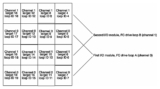
Figure 4-3 diagrams disk addressing for a rackmount RAID system with a full complement of disks in three enclosures.
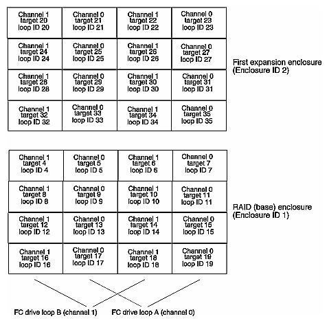
However, you can use TPM to reassign target drives in accordance with your CAP strategy to channels 0 and 1. Check and confirm if the controller parameters need to be modified for the intended application; see the documentation for the management software included with the storage system for information on controller parameters.
System drives are the logical devices that are presented to the operating system. During the configuration process, after physical disk drive packs are defined, one or more system drives must be created from the drive packs. This section discusses system drives in these subsections:
System drives have the following properties:
The minimum size of a system drive is 8 MB; the maximum size is 2 TB.
Each system drive has a RAID level that is selectable (subject to the number of disk drives in the system drive's pack).
Each system drive has its own write policy (write-back or write-through); see “Data Caching” in Chapter 3 for an explanation of this feature.
Each system drive has its own LUN affinity. This capability is further discussed in “System Drive Affinity and Programmable LUN Mapping”.
More than one system drive can be defined on a single drive pack (LUN).
System drive affinity and programmable LUN mapping are configuration features that work together to define how the host accesses the available storage space.
System drive affinity allows system drives to be assigned to any combination of controller and host ports as follows:
Configurations with one RAID controller that has two host ports (through a switch, for example) can use system drive affinity to define affinity of each system drive to one or both host ports.
System drives that are not owned by a controller/host port are not accessible.
Note: The SGI supported topology for multi-path failover is Multi-Port; use the TPM software to set the topology. Caution: If two systems independently access the same volume of data, and the operating system does not support file locking, data corruption may occur. To avoid this, create two or more volumes (or LUNs) and configure each volume to be accessed by one system only.
Programmable LUN mapping lets you assign any LUN ID (even multiple LUN IDs) to any system drive on each port, or configure system drive assignments without specifying the LUN, defaulting to the current mapping algorithm. System drives with the “all” affinity are mapped to a LUN ID on every controller/host port.
The RAID controller sends information about the status of each physical disk drive to the array management software. The controller records the operational state of each drive and a list of available target ID addresses. The controller determines which drives are present and what target IDs are available. Then, it determines the status of the drives that are present. If the disk drive is present, the location of the disk drive is considered configured and the operational state of the disk drive is then determined. If the controller determines the disk drive at the available target ID location is absent, the location of the disk drive is considered unconfigured and the operational state is marked unconfigured, offline, or dead.
If a configured disk drive is removed or fails, and a new disk drive replaces the failed disk drive at the same location, the new disk drive is set to online spare. This allows the automatic rebuild operation to function with replaced drives. When a disk drive is inserted into the system, the controller recognizes that the drive has been replaced. If a configured disk drive fails and the controller loses power or is reset, the disk drive remains offline.
Unconfigured disk drives can be removed and the device state will remain unconfigured. New disk drives added to the system are considered unconfigured until used in a new configuration.
Unconfigured disk drive fault lights (LEDs) are disabled and any insertion, removal, or errors related to these unconfigured devices do not result in fault light activity or error message generation.
If the RAID controller is running firmware version 7.0 or later, COD information is written to all configured drives. Unconfigured drives are not updated; their COD information is set to all zeros.
Table 4-6 describes possible physical disk drive states. This information applies only to physical disk drives, not to system drives.
Table 4-6. Physical Disk Drive States
For more information, see the TPM documentation and online help.
The RAID controller provides automatic rebuild capabilities in the event of a physical disk drive failure. The controller performs a rebuild operation automatically when a disk drive fails and the following conditions are true:
All system drives that are dependent on the failed disk drive are configured as a redundant array; RAID 1, RAID 3, RAID 5, or RAID 0+1;
The Automatic rebuild management controller parameter is enabled;
The Operational fault management controller parameter is enabled; and
A replacement drive with a capacity that is at least as large as the consumed capacity of the failed drive is present in the system.
Note: If a replacement drive of the exact size is not available, the controller selects the smallest replacement drive found with a capacity that is at least as large as the consumed capacity of the failed drive. The consumed capacity is the capacity assigned to the configured system drive(s). If the consumed capacity of the failed disk drive is a percentage of the total capacity, a larger physical disk drive can be rebuilt with a much smaller physical disk drive.
During the automatic rebuild process, system activity continues as normal. However, system performance may be slightly degraded.
| Note: The priority of rebuild activity can be adjusted using the controller parameters to adjust the Rebuild and check consistency rate. |
In order to use the automatic rebuild feature, you must maintain an online spare disk drive in the system. The number of online spare disk drives in a system is limited only by the maximum number of disk drives available on each drive channel. SGI recommends creating an online spare disk drive as part of the original configuration, or soon after creating the original configuration. If the online spare disk drive is created after a disk drive failure has occurred, the automatic rebuild does not start until the controllers have been reset.
A disk drive may be labeled as an online spare using the “create hot spare option” of the TPM configuration utility.
The RAID controllers also support the ability to perform a hot swap disk drive replacement while the system is online. A disk drive can be disconnected, removed, and replaced with a different disk drive without taking the system offline.
| Caution: System drives associated with a failed or removed disk drive become critical. Failure or removal of another disk drive may result in data loss. |
The automatic rebuild feature is dependent upon having an online spare disk drive available or hot swapping the failed disk drive with a replacement drive. If these conditions are not met, the automatic rebuild features does not operate transparently, or without user intervention. Automatic rebuild will not start if an online spare is configured after a disk drive has failed.