This chapter describes how to operate your PCI expansion module. Specifically, it explains how to perform the following procedures:
Tools/Parts Required:
PCI card carrier assembly P/N 013-2614-002
PCI card bracket P/N 040-3880-001 (required for half-height PCI cards)
Optional PCI cards
T8 ballpoint Torx driver P/N 7260654
The PCI expansion module seats as many as twelve PCI cards. The PCI card slots are numbered bus 1 through bus 6. Each bus has two slots, labeled 1 and 2. All slots support either 32- or 64-bit addressing and can accommodate 66-MHz or 33-MHz PCI cards; however, if a bus has one 33-MHz card and one 66-MHz card, the bus operates at 33 MHz.
There are two versions of the PCI expansion module: one module supports twelve 3.3-V or universal PCI cards, and one module supports six 5.0-V or universal PCI cards and six 3.3-V or universal PCI cards. For the PCI expansion module with 5.0-V support, buses 1, 2, and 3 support 3.3-V PCI cards and buses 4, 5, and 6 support 5.0-V PCI cards (see Figure 2-1).

Use the following guidelines when you add PCI cards to your PCI expansion module:
Populate the PCI slots in the following order:
Slot 1 of buses 1, 3, and 5
Slot 1 of buses 2, 4, and 6
Slot 2 of buses 1, 3, and 5
Slot 2 of buses 2, 4, and 6
Avoid mixing 33-MHz and 66-MHz cards on the same 66-MHz bus.
Avoid mixing storage controller cards and networking cards on the same bus.
Make sure the bandwidth of the PCI cards that occupy a bus does not exceed the bandwidth of the bus.
Although you need not power off the rack or the PCI expansion module to add or replace a PCI card, you must power off the individual slot in which you will replace a PCI card. For more information about powering off an individual slot, see “Hot-plugging a PCI Card ”.
To add or replace a PCI card, follow these steps:
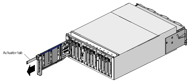
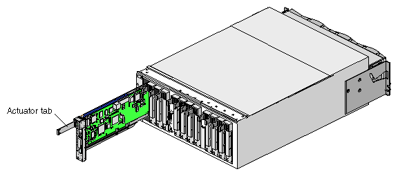
Remove the PCI carrier from the PCI slot in which you want to add or replace a PCI card. Pull out the PCI carrier actuator tab to extract it from the PCI slot; grasp the PCI card carrier by its edges and slide it out of the module, as shown in Figure 2-2.
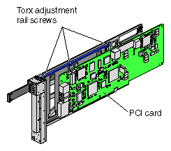
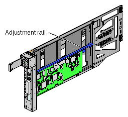
If you are replacing a card, loosen the three T8 Torx adjustment rail screws (see Figure 2-3) and gently remove the existing PCI card from the carrier.
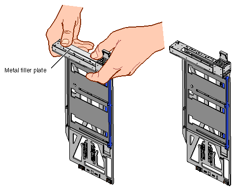
If you are adding a PCI card, extract the metal filler plate by pushing down on it as shown in Figure 2-4. This filler plate covers the PCI-card connector area.

Note: If you are adding or replacing a half-height PCI card, proceed to step 4. For a full-height PCI card, place the new or replacement PCI card in the PCI card carrier. If necessary, move the adjustment rail so that it holds the card in place.
Tighten the three T8 Torx adjustment rail screws to secure the card in the carrier. See Figure 2-5.
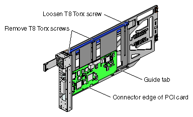
For a half-height PCI card, remove the two T8 Torx screws from the adjustment rail, as shown in Figure 2-6.
Note: Take care not to lose the threaded inserts in the adjustment rail. Loosen the third screw of the adjustment rail.
Place the half-height PCI card in the carrier so that the connector edge of the card rests against the lower guide tab of the carrier (see Figure 2-6).
Move the adjustment rail so that it holds the card firmly in place (see Figure 2-7).
Place the PCI card bracket so that the screw holes of the bracket align with the empty screw holes of the alignment rail, as shown in Figure 2-8.
Secure the bracket to the alignment rail with two T8 Torx screws.
Insert the PCI card and carrier into the vacant slot, using the slot guides, as shown in Figure 2-9. Then slide the carrier into the module by grasping the PCI card carrier by its edges and sliding it into the module.
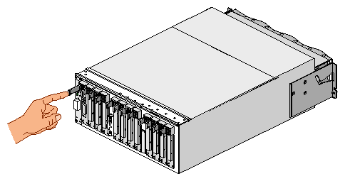
Push in the PCI card actuator tab until the card seats in its slot (see Figure 2-10).
Connect any cables to the PCI card.
Power on the PCI slot. See “Hot-plugging a PCI Card ”.


You can add and remove (hot-plug) certified controller cards while the system is powered on; however, only certified device drivers support PCI hot-plug operations. An attempt to hot-plug a card that does not have a certified driver will fail. For information on specific certified device drivers, contact your service representative.
You can hot-plug a 66-MHz card only in an empty bus (both PCI slots are empty). When you install a card in a bus that already contains a card, the bus operates at the speed of the existing card.
To install a certified PCI card (for example, QLogic Fibre Channel and SCSI controller cards), follow these steps:
Insert a supported card into an empty PCI slot. See “Installing and Removing a PCI Card”.
Use the pciconfig command to bring the PCI card online.
In the following example, the pciconfig command powers on PCI slot 1 in bus 3 of the PCI expansion module in location U30. It also determines the type of card installed and calls the appropriate device driver to initialize the card and its software.
pciconfig -b /hw/module/001p30/Pbrick/bus/3/pci -s 1 -u
The -b option specifies /hw/module/001p30/Pbrick/bus/3/pci as the path to bus 3 in the PCI expansion module, the -s option specifies slot 1, and the -u option indicates that you want to hot-plug (insert) a card in the specified slot. For a description of these options, see the pciconfig(1M) man page.
After a successful hot-plug insertion, the system runs as if the card were installed at boot time.
Check the hardware graph for the new device entries.
Typically, new device entries are found in the hardware graph. The hardware graph, which is maintained by the IRIX operating system, represents the collection of all significant system hardware. The hardware graph is not really a graph; it is a directory structure that includes all of the system hardware. To view this directory structure, change to the /hw/module directory. From this directory, you can continue to view different directories to determine the hardware that composes a system.
You can also use the pciconfig command to remove a card from a running system and to queue the status of the slot before and after a hot-plug operation. For more information on these operations, see the pciconfig(1M) man page.
The following subsections describe how to power on and power off your PCI expansion module:
This section describes how to perform the following procedures:
Preparing to power on
Powering on at the system console that is connected to the L2 controller
Powering on at the system console that is connected to a compute module
Powering on with power switches
To prepare to power on the PCI expansion module, perform the following tasks:
Confirm that the power cable between the power bay and the PCI expansion module is secure.
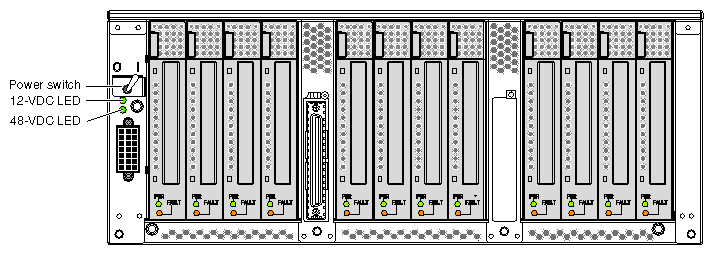
Power on the L1 controller by setting the power switch on the rear of the PCI expansion module to the 1 position. See Figure 2-11. The 12-VDC LED, which is located on the rear of the module, illuminates when the L1 controller is powered on.
Ensure that the L1 controller of the PCI expansion module is running; the L1 display should display “L1 running.” If the L1 controller is not running, contact your SGI system support engineer (SSE).
To power on your PCI expansion module by using the system console that is connected to the L2 controller, follow these steps:
At the system console, access the L2 controller by entering the following command:
$> /stand/sysco/bin/12term
From the L2 prompt (L2>), power on the PCI expansion module by entering the following command. (If you want to power on the entire system, proceed to step 3.)
L2> r <rack#> s <slot#> pwr u
For example, to power on a PCI expansion module in rack 1, slot 10, enter the following command line:
L2> r 1 s 10 pwr u
The slot number is the unit number of the module within the rack. For more information about unit numbers, see Chapter 1 of this document.
If you want to power on several selected modules of a rack at the same time, you must enter the rack number followed by the slot numbers of the modules that you want to power on. For example, to power on the PCI expansion modules in slots 10 and 28, enter the following command:
L2> r 1 s 10,28 pwr u
If you want to power on the entire system, enter the following command:
L2> pwr u
(The default setting for the pwr u command is all slots.)
The 48-VDC LED (rear of module) and the On/Off LED (front of module) illuminate when the module is powered on.
From the L2 prompt, display the system configuration by entering the following command:
L2> config
This command lists the modules in the system and their system controller addresses.
To power on your PCI expansion module by using the system console that is connected to an SGI 300 compute module, enter the following command at the system console:
001c01-L1> ctc pwr u |
The 48-VDC LED (rear of module) and the On/Off LED (front of module) illuminate when the module is powered on.
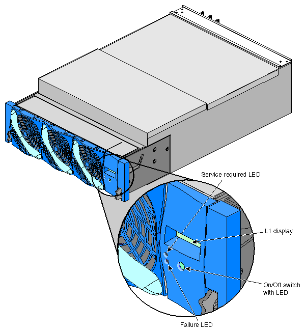
To power on your PCI expansion module by using the power switches , press the On/Off switch that is located on the front of the module (see Figure 2-12). The 48-VDC LED (rear of module) and the On/Off LED (front of module) illuminate when the module is powered on.
This section describes three methods for powering off your PCI expansion module, as follows:
Powering off at the system console that is connected to the L2 controller
Powering off at the system console that is connected to a compute module
Powering off with power switches
To power off your PCI expansion module by using the system console that is connected to the L2 controller, follow these steps:
Access the L2 controller by entering the following command:
$> /stand/sysco/bin/12term
From the L2 prompt (L2>), power off an individual module by entering the following command. (If you want to power off the entire system, proceed to step 3.)
L2> r <rack#> s <slot#> pwr d
For example, to power off the PCI expansion module in rack 1, slot 10, enter the following command:
L2> r 1 s 10 pwr d
The slot number is the unit number of the module within the rack. For more information about unit numbers, see Chapter 1 of this document.
If you want to power off several selected modules from the rack at the same time, enter the rack number followed by the slot numbers of the modules that you want to power off. For example, to power off the modules in slots 10 and 28, enter the following command:
L2> r 1 s 10,28 pwr d
If you want to power off all of the modules within the rack, enter the following command:
L2> pwr d
(The default setting for the pwr d command is all slots.)
From the L2 prompt, display the configuration information by entering the following command:
L2> config
This command lists all of the modules in the system and their system controller addresses.
Power off the L1 controller by setting the power switch on the rear of the module to the 0 position. See Figure 2-11.
To power off your PCI expansion module by using the system console that is connected to an SGI 300 compute module, follow these steps:
At the system console, enter the following command:
001c01-L1> ctc pwr d
Power off the L1 controller by setting the power switch on the rear of the module to the 0 position. See Figure 2-11.
To power off your PCI expansion module by using the power switches , follow these steps:
Press the On/Off switch that is located on the front of the module (see Figure 2-12). The 48-VDC and On/Off LEDs should not be illuminated when the module is powered off.
Power off the L1 controller by setting the power switch on the rear of the module to the 0 position. See Figure 2-11.
You can monitor your PCI expansion module from the following sources:
You can view the status of an individual module and error messages via the module's L1 controller display. For example, you can determine whether the fans of a particular module are operating properly.
The system console enables you to view the status and error messages that are generated by the L1 and L2 controllers.