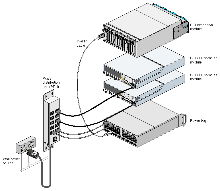
This chapter describes the steps that you must perform to install your PCI expansion module in a tall or short rack. Specifically, it explains how to perform the following procedures:
The placement of the PCI expansion modules within the rack depends on the system configuration and rack type. This section discusses the following:
Determining placement within a short rack
Determining placement within a tall rack

Note: Within the rack, a PCI expansion module is identified by the lowest unit number that it occupies. For example, in Figure 1-1, the PCI expansion module in the short rack is identified as U14. The top PCI expansion module in the tall rack is identified as U30.

A system that is housed in a short rack can contain one or two PCI expansion modules. These modules should be placed in the first available location above the SGI 300 compute modules.
For example, in a system that contains a NUMAlink module (see Figure 1-2), place the first PCI expansion module in location U10. If you are adding a second PCI expansion module, place it in location U14. In a system that does not contain a NUMAlink module, place the first PCI expansion module in location U06 and place the second module in location U12.

A tall-rack system with a NUMAlink module can contain as many as four PCI expansion modules. The number of modules depends on the following:
The number of compute modules in your system; the PCI expansion module must be paired with an SGI 300 compute module (for example, an Origin 300 server or an Onyx 300 compute module).
The number of available ports on the NUMAlink module.
Note: The PCI expansion module must connect to port 2, 3, 4, or 5 of the NUMAlink module. The PCI expansion module will not function if it is connected to port 1, 6, 7, or 8 of the NUMAlink module.
Table 1-1 lists the number of supported PCI expansion modules for a tall-rack system that contains a NUMAlink module.
Table 1-1. Number of Supported PCI Expansion Modules
Number of Compute Modules | Maximum Number of Supported |
|---|---|
Two | Two |
Three | Three |
Four | Four |
Five | Three |
Six | Two |
Seven | One |
Eight | Zero |
The PCI expansion modules should reside above and below the NUMAlink module and the SGI 300 compute modules. Place the first PCI expansion module in the highest available location in the bottom section of the rack. For example (see Figure 1-3), place the first PCI expansion module in U12. Place the second PCI expansion module in the first available location in the top portion of the rack (for example, U26). Continue to alternate between the top and bottom portions of the rack until all of the PCI expansion modules are installed.

A tall-rack system without a NUMAlink module can contain as many as six PCI expansion modules. The number of PCI expansion modules depends on the number of compute modules in your system. The PCI expansion module must be paired with an SGI 300 compute module; therefore, the system must contain at least six compute modules to support six PCI expansion modules.
Ideally, the PCI expansion module should be placed directly above the SGI 300 compute module to which it will be cabled (see Example A in Figure 1-4); however, if your configuration is similar to the one shown in Example B, place the PCI expansion module in the first available location above the compute modules.

The PCI expansion module ships with shelf rails that you need to mount to the rack. The shelf rails support the PCI expansion module within the rack.
To mount the shelf rails to the rack, follow these steps:
Locate the slot location in the rack where you will install the PCI expansion module.
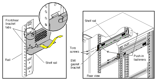
In the slot location from step 1, position the left shelf rail at a 90-degree angle to the front and rear rack rails (see Figure 1-5).
Insert the top-front bracket tab into one of the narrow slots in the front rack rail.
Insert the top-rear bracket tab into the narrow slot in the rear rack rail.
Note: Verify that the tabs are the same height to ensure that the module is level in the rack. Lower the bottom of the shelf rail until its two lower tabs engage with the wide slots in the front and rear rack rails.
Install the two push-in fasteners that secure the shelf rail to the front and rear rack rails.
Place the EMI gasket bracket on the rear rack rail. Then install the two T25 Torx screws that secure the bracket and the shelf to the rear rack rail.
Repeat steps 2 through 7 for the right shelf rail.
Perform the following steps to install the PCI expansion module in your system. SGI recommends that you use a service shelf during the installation. The PCI expansion module weighs approximately 70 lbs (31.5 kg).
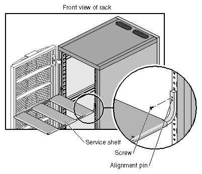
To attach the service shelf to the rack, follow these steps:
Insert the alignment peg of the service shelf into the rack rail so that the shelf is at the same height as the slot in which you will install the PCI expansion module.
Insert two M5 Phillips screws to secure the shelf to the rack.
Place the module on the service shelf; the connector end of the module should be closest to the rack.
Slide the module off of the service shelf and into the rack.
Do not slide the module all the way into the rack. Leave enough space between the module and the rack rail so that you can remove the screws that secure the shelf to the rack rail. After you remove the shelf, slide the module completely into the rack.
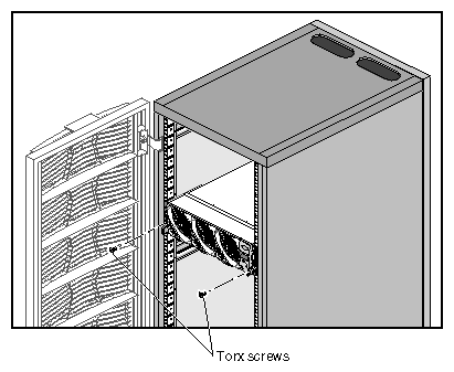
Install the two T25 Torx screws that secure the module to the front of the rack. See Figure 1-7.
This section describes how to cable your PCI expansion module to an SGI 300 compute module and to a NUMAlink module. Refer to the procedure that applies to your system configuration. This section also describes how to cable the PCI expansion module to the power bay.
Cable the PCI expansion module to the LINK (NI) connector of an SGI 300 compute module that is within 8U of the PCI expansion module (see Figure 1-8).
| Note: The NUMAlink cable is 1 meter in length (39 inches); however, after subtracting the allowance for cable bends (12 in., 0.3 m) and cable management (12 in., 0.3 m), you should cable the PCI expansion module to an SGI 300 compute module that is not more than 8U away from the PCI expansion module. |

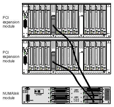
In a system that contains a NUMAlink module, the PCI expansion modules connect to ports 2, 3, 4, and 5 of the NUMAlink module.
| Note: The PCI expansion module will not function if it is connected to port 1, 6, 7, or 8 of the NUMAlink module. |
Table 1-2 and Table 1-3 indicate the NUMAlink port to which you should cable your PCI expansion module. Table 1-2 provides this information for a short rack. This table indicates that, for example, if your module resides in location U10, you should connect it to NUMAlink port 3.
Table 1-2. Connecting PCI Expansion Module to NUMAlink Module in Short Rack
If your PCI expansion module resides in this location | Connect to this NUMAlink module port |
|---|---|
U10 | 3 |
U12 | 3 |
U14 | 2 |
Table 1-3 provides the NUMAlink port information for a tall rack. This table indicates that, for example, if your module resides in location U8, you should connect it to NUMAlink port 4.
Table 1-3. Connecting PCI Expansion Module to NUMAlink Module in Tall Rack
If your PCI expansion module resides in this location | Connect to this NUMAlink module port |
|---|---|
U8 | 4 |
U10 | 4 |
U12 | 5 |
U26 | 3 |
U28 | 2 |
U30 | 2 |
Figure 1-9 provides an illustration of the cabling between the NUMAlink module and the PCI expansion modules in a tall rack.
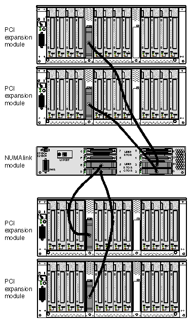
Figure 1-10 provides an illustration of the cabling between the NUMAlink module and the PCI expansion modules in a short rack.
You must also cable the PCI expansion module to the power bay as shown in Figure 1-11. The PCI expansion module can connect to one of the following power bays:
The 110-VAC power bay contains two power supplies; each power supply inputs single-phase AC power and outputs 650 W at 48 VDC. The outputs are bused together to provide 1250 W of available power in an N+1 redundant configuration.
Each power supply also outputs 12-VDC standby voltage at 42 W. The outputs are bused together to provide 90 W of available power in an N+1 redundant configuration.
The 220-VAC power bay also contains two power supplies; each power supply inputs single-phase AC power and outputs 950 W at 48 VDC. The outputs are bused together to provide 1840 W of available power in an N+1 redundant configuration.
Each power supply also outputs 12-VDC standby voltage at 42 W. The outputs are bused together to provide 90 W of available power in an N+1 redundant configuration.
Both power bays supply the 12-VDC standby voltage and the 48 VDC to the PCI expansion module. The 12-VDC standby voltage powers on the module `s L1 controller. The 48 VDC powers on the other components within the module.