This chapter describes various tasks you must perform to complete the initial configuration your site. It contains the following sections:
This task lets you define a new node. After defining the node, you can use Console Manager to perform functions such as reset, power up, power down, get console, and spy console by running tasks from the Node Tasks pulldown menu.
The following tables shows which fields are required for various node types (see step 2 for more information on node types):
| Node Type | Fields Required | |
| All Nodes | Node name, user name, hostname for this node | |
| L2 | Partition number, L2 address | |
| L1 | System Controller TTY device name | |
| MSC | System controller TTY device name, console TTY device name, system controller password (optional), Serial speed. | |
| MMSC | System controller TTY device name, system controller password (optional). |
To add a node to Console Manager, follow these steps:
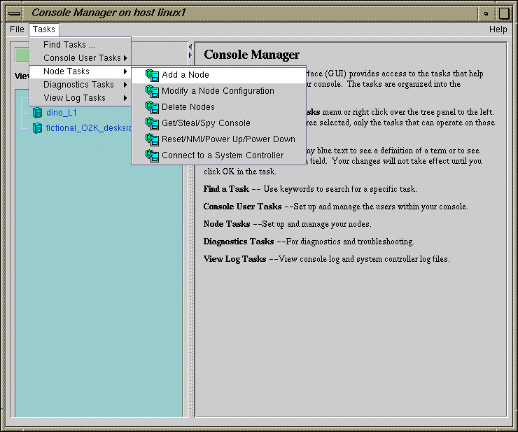
From the Tasks pulldown menu, choose the following, as shown in Figure 3-2.
Node Tasks -> Add a Node
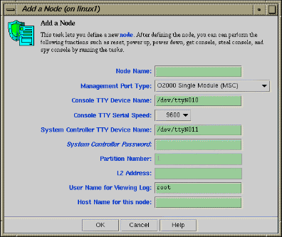
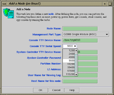
The Add a Node Dialog dialog box appears, as shown in Figure 3-2.
In the Add a Node Dialog Box fields, add the following information:
The host name is for rsh access to the node managed by the Console Manager. This host name is not the same as the SGIconsole host name but may be the same as the node name assigned in the Node Name field. You need a .rhosts entry for the SGI 1100 system on the target system.Node Name: The name you want to assign to this node, such as lightning1.
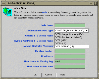
Management Port Type: From the Management Port Type pulldown menu (see Figure 3-3) choose one of the following node types:

Note: When you select a type, the non-applicable fields are deactivated.
Note: Console Manager does not support any connection types not provided by SGI. Only the following nodes can be added: SGI Origin 200, SGI Origin 2000, Silicon Graphics Onyx2, SGI Origin 300, SGI Origin 3000, SGI Origin 300 with a NumaLink module and a Silicon Graphics Onyx 3000. Any node that does not support MMSC, MSC, L1 or L2 protocols will not work. 02000 Single Module (MSC) SGI Origin 2000 system with a single module System Controller (MSC)
02000 Rackmount Module (MMSC) SGI Origin 2000 rackmount system with a multimodule System Controller (MMSC)
0200 (MSC) SGI Origin 200 system with MSC
03000 (L2) SGI Origin 3000 system with rack-level L2 system controllers
0300 (L1) SGI Origin 300 system with an L1 system controller or an SGI Origin 3200C system with an L1 system controller
Console TTY Device Name: The device name of the port that is connected to the console port on the node, such as /dev/ttyN011, which would be port 12 on the EL-16 unit. This field is not applicable for L2 management port type.
Console TTY Serial Speed: If you selected the 02000 Single Module (MSC) or 0200 (MSC) Management Port type from the pulldown menu, select one of the following baud rates: 300, 1200, 2400, 4800, 9600, 19200, 38400, or 57600, as shown in Figure 3-4.
For MMSC and L2 Management Port types, this field is disabled.System Controller TTY Device Name: Name of the terminal port (TTY) on the EL-16 unit to which the system controller is connected, such as /dev/ttyN012. The other end of the cable connects to this node's system controller port, so the node can be controlled remotely by the other node.
System Controller Password: The password for the system controller port, not the node's root password or PROM password. On some machines, the system administrator may not have set this password. If you wish to set or change the system controller port password, consult the hardware manual for your node.
Partition Number: Uniquely defines a partition in a partitioned SGI Origin 3000 system. Valid partition numbers range from 1 to 256. This is a required parameter for SGI Origin 3000 systems with an L2 controller. If your system is not partitioned, enter zero in this field.
L2 Address: L2 system controller Internet Protocol (IP) address of the private network or hostname. You can either enter a resolvable hostname, a fully qualified hostname, such as name.sgi.com. or an IP address, such as 192.1.2.3. This is a required parameter for SGI Origin 3000 systems with an L2 controller.
User Name for Viewing Log: Example: Root user. This user name is used to log into the node to obtain the logs to display.
Host Name: Hostname of the node you are defining, such as mynode.company.com.
Click the OK button.
An error message appears if the task fails.
An icon entry appears on the View panel.
This tasks allows you delete a node or group of nodes.
To remove a node from Console Manager, follow these steps:
From the Tasks pulldown menu, choose the following, as shown in Figure 3-2.
Node Tasks -> Delete Nodes
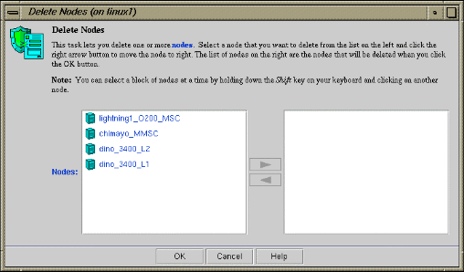
The Delete Nodes dialog box appears, as shown in Figure 3-5.
Select a node that you want to delete from the list on the left and click the right arrow button to move the node to the right. The list of nodes on the right are the nodes that will be deleted when you click the OK button. You can select a block nodes at a time by the holding down the Shift button on your keyboard and clicking on another node.
Click the OK button
An error message appears if the task fails.
The icon entry is removed from the View panel.
This task lets you modify a node. You select the node to modify by clicking on the down arrow button on the Node Name tab.
To modify a Node configuration, follow these steps:
From the Tasks pulldown menu, choose the following:
Node Tasks -> Modify Node configuration
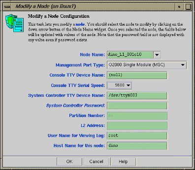
The Modify a Node Configuration dialog box appears, as shown in Figure 3-6.
In the Modify a Node Configuration dialog box fields, modify the fields as required. For an explanation of each field, see “Adding a Node”.
Click the OK button
If you attempt to modify a node in a way not allowed by the Console Manager, an error message appears.