This chapter explains how to add or replace components in a node. It consists of these sections:
Follow electrostatic discharge (ESD) precautions when you handle components or work inside a node. Electronic equipment can be irreparably damaged by ESD. Always follow these preventative measures when handling a system component:
Remove a component from its antistatic bag only when you are about to install it.
If you must handle a component before installation, do not place it on surfaces that produce ESD (carpeting, for example), or near devices that create static electricity.
Attach a wrist grounding strap before handling electronic components. Wrist grounding straps are available at most electronic component stores.
To replace a drive in a node, you remove the drive cage (rotational module), remove the drive in question, install the replacement drive, and replace the drive cage in the chassis. For this procedure, you need the following:
#2 Phillips screwdriver
Grounding wrist strap
This section explains how to replace a 5.25-inch or 3.5-inch drive, and also how to replace or add a drive cage, in these subsections:
“Replacing or Adding a Drive Cage ”

Note: If you are adding drives to a new drive cage, note that you cannot add more than two drives to the additional optional drive cage.
To remove the system drive cage, follow these steps:
If you are not replacing the drive cage immediately, have ready four bezel blanking plates.

Caution: If a drive cage is missing, bezel blanking plates must be installed for proper emissions control. Make sure adequate room on the workbench is available for the drive cage.
Make sure all users have logged off the affected node. Shut down the node with the appropriate administrative tools.
Open the node bezel (see “Opening a Node Bezel” in Chapter 4) and power off the node; see Figure 3-3 for the button location.
Remove the node top cover by following the instructions in “Removing a Node Cover ” in Chapter 4.
Attach a static wrist strap to a grounded connection on your system.
Disconnect all cables from drives in the cage; see Figure 5-1.
SCSI drives: Detach the SCSI ribbon cable at the drive end; detach the drive power cable.
Floppy drive in the system drive cage: Detach the power cable (red, black, black, yellow) from the drive; detach the floppy drive cable from the motherboard.
CD-ROM drive in the system drive cage: Detach the IDE cable at the drive end. Detach the power cable.
Root drive in the system drive cage: Detach the SCSI connection at the drive end. Detach the power cable from the drive.
Front panel LED and switches in the system drive cage: Detach the three-headed power supply cable from the motherboard.
If you are not replacing the drive immediately, you can detach its cables at the other end as well.
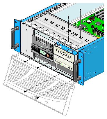
Note: Figures in this section show details for the original drive cage shipped from the factory; however, instructions and details apply also to an optional second drive cage, except where noted. Note: It is a good idea to note carefully all cabling that you detach. Unscrew the four screws (two on top flange, two on bottom flange) that attach the front of the drive cage to the front of the node chassis; see Figure 5-2.
Remove the two screws at the top of the drive cage; see Figure 5-2.
Pull up on the chassis top panel slightly to free the drive cage from the clips on the top panel, and push the drive cage forward and out of the chassis, as shown in Figure 5-3.
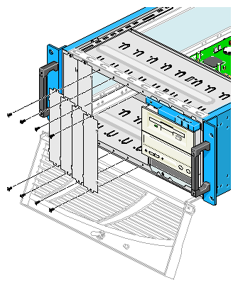
If you are removing an optional second drive cage and not replacing it right away, install four blanking plates at the front of the node, starting at the left side of the node chassis front. Screw in each one at the top and the bottom; see Figure 5-4.
Caution: If a second drive cage is not present, bezel blanking plates must be installed for proper emissions control.


To remove a drive from a drive cage, follow these steps:
If you are not replacing the drive immediately, have ready a drive filler plate.
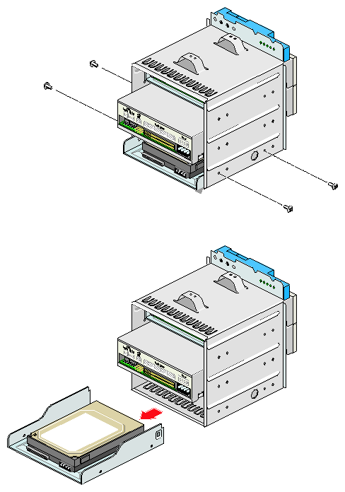
Caution: If a drive is missing, a filler plate must be installed in the drive cage for proper emissions control. Unscrew the two screws on each side of the drive cage that secure the drive, as shown in Figure 5-5.
If you are not replacing the drive, install a drive filler plate in the drive bay. Secure it with a screw at either end.
Caution: If a drive is missing, a filler plate must be installed for proper emissions control.
The drive cage included in the chassis ships with three drives (floppy drive, CD-ROM drive, and system drive); all are nonremovable.
The node chassis accommodates one additional drive cage, available from SGI as an option; it holds two additional drives (removable or nonremovable). Nonremovable drives from SGI are premounted on drive sleds for the SGI Graphics Cluster drive cages.
| Note: You cannot add more than two drives to the additional optional drive cage. |
To replace or add a drive, follow these steps:
If you are installing a drive in a drive cage that is already in the node chassis, remove the drive cage from the node by following the instructions in “Removing a Drive Cage from a Node Chassis ”.
Have ready the new drive and all its cables.
Select a drive bay for the new drive in the drive cage.
If you are installing a removable drive or a tape drive in an optional new drive cage, remove the screws at the right and left ends of the blanking plate for the drive bay you select.
Do not remove the blanking plate if you are installing a drive that can be inserted from the rear of the drive cage, such as a nonremovable drive.
Note: In an optional additional drive cage, drives are installed in the top two drive bays only. No drive can occupy the bottom drive bay. Insert the drive into the rear of the selected drive bay. A removable drive can be inserted from either direction.
Align holes in the drive with holes in the sides of the drive cage. Screw the drive into the drive cage with four screws (two on each side of the drive cage), as shown in Figure 5-5. Screws are included with the drive.
Caution: Screws included with various drives are not interchangeable. Be sure to use only the screws included with the option.
A new optional drive cage includes the following:
SCSI ribbon cable
Narrow blanking panel
Optional drive, as ordered (hard disk, tape drive, or other); nonremovable drives are premounted on drive sleds
Sufficient screws
Note: If you must remove the node because it is awkward to add the drive cage to it, ask another person to help you remove and replace the node.
To replace (reinstall) a drive cage or to add a new optional drive cage in a node chassis, follow these steps:
With the drive cage on a work surface, install any drives needed in the drive cage; see “Installing a Drive in the Drive Cage ”.
Pull out the node in which you are installing the drive cage by following the instructions in “Preparing a Node for Component Replacement or Addition” in Chapter 4. Remove the node cover.
Note: If it is awkward to work on the node in the rack, ask another person to help you remove it from the rack and to replace it in the rack. Follow the instructions in “Removing a Node from a Rack ” in Chapter 4. If you are adding a new drive cage, follow these steps:
Working from right to left, remove the four vertical blanking plates from the front of the node chassis; see Figure 5-6.
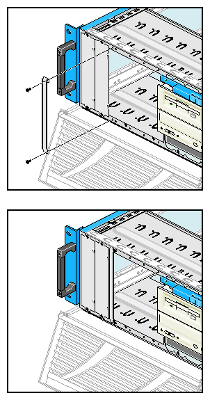
At the front of the node, attach the narrow plate included with the new drive cage; screw in the plate at the top and bottom, as shown in Figure 5-7.
Push the drive cage into the chassis. The drive cage clicks into place; clips at the top of the chassis hold it in place. See Figure 5-3.
Screw in the two screws that attach the drive cage to the top of the node. Screw in the four screws (two on top flange, two on bottom flange) that attach the front of the drive cage to the front of the node chassis. Snap the top plastic panel back onto the drive cage to cover the screws. See Figure 5-8.
Cable the drives as follows:
SCSI drive: Attach the single connector on the SCSI ribbon cable to the SCSI connector on the motherboard. Attach one of the connectors along the cable to the SCSI connector on the drive. The connectors are keyed.
Remove the tie wrap from the power cables and select a power cable that reaches the drive; connect it.
Floppy drive: Attach the IDE floppy drive cable to the drive. Attach a power cable (red, black, black, yellow) from the node's power supply to the drive.
CD-ROM: Connectors are labeled on the drive's panel.
Attach the IDE cable at the drive end. Attach a power cable. Attach an IDE cable from the drive to an IDE connector on the motherboard.
Root drive: Attach the SCSI connection at the drive end. Attach a power cable.
Attach the single end of the three-headed power supply cable (white-blue, white-green, gray-gray) to the connector on the root drive. Attach the three-headed end as shown in Figure 5-9.
Replace the node's top panel as described in “Removing a Node Cover ” in Chapter 4. Push the node back into the rack as described in “Pulling a Node Out of the Rack” in Chapter 4. Recable the node as described in “Cabling the Node and Finishing” in Chapter 4.
To remove and replace a system fan, follow these steps:
Open the node bezel (see “Opening a Node Bezel” in Chapter 4) and power off the node; Figure 3-3 shows the location of the button.
Remove the node top cover, following instructions in “Removing a Node Cover ” in Chapter 4.
Attach a static wrist strap to a grounded connection on your system.
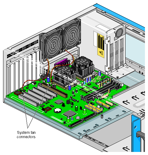
Disconnect the fan cable from the motherboard; see Figure 5-10.
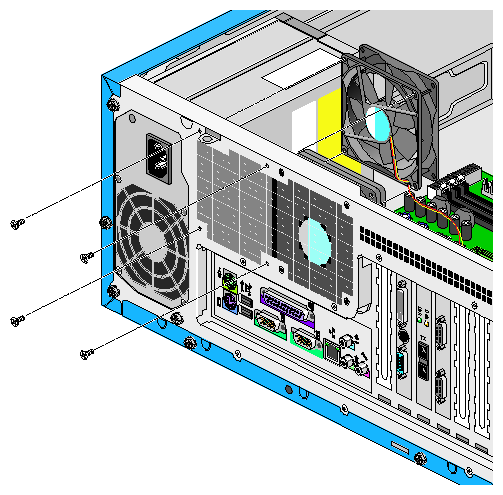
Note: The cable of the left fan is routed under the PCI cards. After pulling the fan cable connector off the motherboard, you can gently pull the cable under the cards, or you can temporarily remove the cards if desired. At the back of the node chassis, unscrew the four screws (one in each corner) that secure the fan to the chassis back; see Figure 5-11. Retain the screws for the replacement fan.
Carefully remove the fan from the system without touching any system component.
Insert the replacement fan into the chassis; screw it in with the reserved screws.
Connect the fan cable; see Figure 5-10. For the fan closest to the expansion slots, you might have to lift the cards out of the slots to route the cable.
This section describes how to install and remove PCI and AGP cards.
Follow electrostatic discharge (ESD) precautions. Electronic equipment can be irreparably damaged by ESD:
Remove a card from its antistatic bag only when you are ready to install it.
If must handle a card before installation, do not place it on surfaces that produce ESD (carpeting, for example), or near devices that create static electricity.
Note: In an SGI Graphics Cluster Series 12 node, do not remove or replace the graphics card that is in the AGP slot; do not remove the SGI ImageSync card. For these procedures, contact your service representative.
Expansion cards in the SGI Graphics Cluster occupy specific slots, as outlined in Table 5-1.
Table 5-1. Expansion Slots and Cards in the SGI Graphics Cluster
Slot | Card |
|---|---|
AGP | Graphics card |
PCI slot 1 (closest to the AGP slot) | Optional gigabit Ethernet card |
PCI slot 2 | SGI ImageSync card; SGI Graphics Cluster Series 12 only |
PCI slot 3 | Network interface card (secondary Ethernet), master node only; included with SGI Graphics Cluster Series 12 |
PCI slot 4 | Empty; available for customer option |
PCI slot 5 (closest to the chassis wall) | Commercial audio card: included with master node of SGI Graphics Cluster Series 12 |
| Note: The motherboard has six expansion slots; a seventh slot cover to the left of the AGP slot accommodates additional ports on an AGP card. However, in an SGI Graphics Cluster node, the AGP slot is occupied by the graphics card. |
To i nstall an expansion card, follow these steps:
With the node powered off and pulled out of the rack and with the node's top panel off, attach a static wrist strap to a grounded connection on your system.
Locate an empty expansion slot on the motherboard; Figure 5-12 numbers the PCI slots.
Note: In an SGI Graphics Cluster Series 12 node, do not remove or replace the graphics card that is in the AGP slot; do not remove the SGI ImageSync card. For these procedures, contact your service representative. Remove the slot cover (metal bracket) for the empty expansion slot. Retain the screw for use with the new card.
Note: It is a good idea to retain slot covers in case cards must be removed and no new cards are inserted into the slots. Unwrap the expansion card; do not touch the card's connector. Insert the card carefully and firmly into the slot. Make sure that the card is properly seated.
Secure the card to the housing with the screw from the slot cover.

To remove an expansion card, follow these steps:
If you are removing a card but not inserting another in the slot, have ready a slot cover.
Caution: If a card is missing, a slot cover must be installed to minimize radiated emissions. With the node's top panel off, attach a static wrist strap to a grounded connection on the system.
Remove the retaining screw for the expansion card you are removing.
Note: In an SGI Graphics Cluster Series 12 node, do not remove or replace the graphics card that is in the AGP slot; do not remove the SGI ImageSync card. For these procedures, contact your service representative. Gently and evenly pull the card straight up and out of the slot.
If you are not installing another card in the empty slot, install a slot cover in the expansion slot opening, and screw it in.
Replace the top panel as shown in “Removing a Node Cover ” in Chapter 4.
When the system is turned on, the BIOS automatically detects and assigns resources to the new device.
The three 168-pin sockets on the motherboard support SDRAM registered ECC DIMMs. You can install 256-MB or 512-MB (single- or double-density) DIMMs for a maximum of 1 GB of system memory. Each DIMM socket is independent from the others; you can install DIMMs with different capacities to form different configurations.
| Note: The SDRAM works at 3.3 volts only; 5-volt memory devices are not supported. This motherboard supports 100-MHz and 133-MHz SDRAM. However, they cannot be used at the same time in the system. |
 | Warning: Using both 100-MHz and 133-MHz SDRAM together might cause your system to malfunction. For a qualified DIMM vendor list, please contact your SGI representative. |
To install a DIMM, align it with an empty slot and press it in until the holding clips secure the DIMM in place, as shown in Figure 5-13.
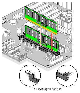
| Note: The DIMM socket is slotted to ensure proper installation. If you insert a DIMM but it does not completely fit, you may have inserted it the wrong way. Reverse the orientation of the DIMM. |
To remove a DIMM, press the holding clips on both sides of the socket outward to release the DIMM, as shown in Figure 5-13. Place your fingertips on the top of the DIMM before you press the holding clips to gently disengage the DIMM from the socket.
The system automatically detects the amount of memory installed. For configuration information, consult a reference work on your cluster's operating system, as follows:
Linux in a Nutshell, Ellen Siever, Stephen Spainhour, Jessica P. Hekman, and Stephen Figgins, third edition, O'Reilly & Associates, 2000, ISBN 0-596-00025-1
Windows NT in a Nutshell, Eric Pearce, O'Reilly & Associates, 1997; ISBN 1-56592-251-4, or Essential Windows NT System Administration, second edition, AEleen Frisch, O'Reilly & Associates, 1998, ISBN 1-56592-274-3