This chapter consists of the following sections:
“Removing the Rack Rear Door ”

Note: For procedures in this chapter, you need a #2 Phillips screwdriver. Attaching slide rails to the rack also requires a nut driver. It is strongly recommended that an additional person assist in removing a node from a rack.
This section explains the following:
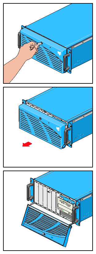
For some operations, such as removing or replacing disk drives, you must open the node bezel. Follow these steps:
Unlock the node bezel using the key provided. The keys (two for each node) are shipped attached to the rack door; the keys are identical.
Pull the bezel out and away from the node, and swing the bezel down, as shown in Figure 4-1.
To replace a component in a node, it is usually sufficient to pull the node out from the rack on its extensible slide rails, where it locks into place. To pull a node out of the rack so that it can be worked on, follow these steps:
 | Warning: When adding or servicing equipment in the rack, do not pull out more than two nodes at a time. |
Make sure all users are logged off the affected system(s) and that data is backed up, if necessary. Shut down the system with the appropriate administrative tools.
Open the node bezel by following the instructions in “Opening a Node Bezel”.
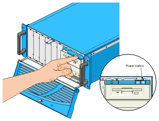
Power off the node with the button at the far right above the floppy disk drive; see Figure 4-2.
At the back of the rack, detach the node's power cable from its socket on the node. See Figure 4-3.
For an SGI Graphics Cluster Series 12 system, disconnect the daisy-chain cable from the node's external SGI ImageSync connector; see Figure 4-4. Channel nodes are daisy-chained to the nodes above and below.
Disconnect other cables, such as those for peripherals, Ethernet, and external options.
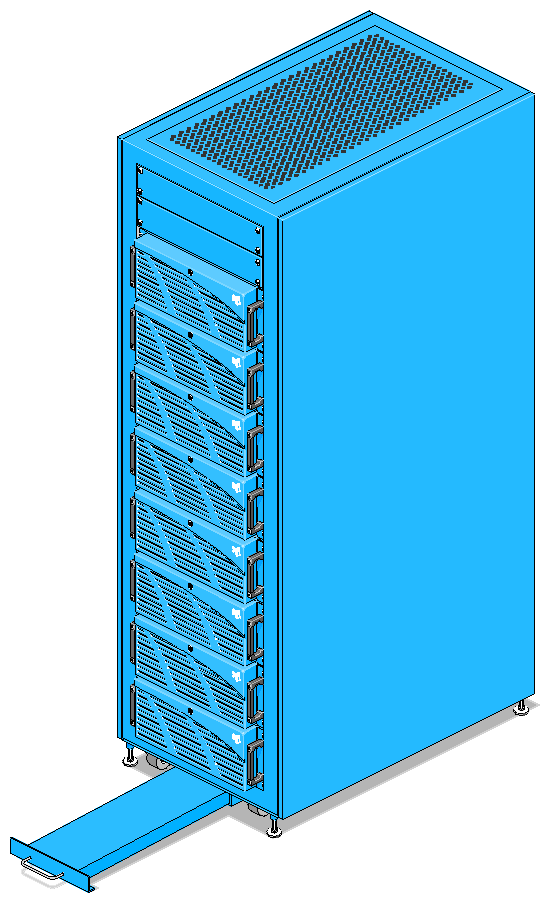
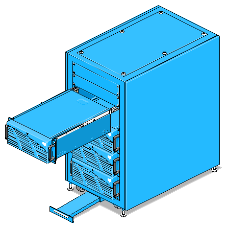
If you are pulling out a node, pull out the rack's anti-tip shelf; see Figure 4-5.
Warning: Be sure to pull out the anti-tip shelf before you pull out a node. Failure to do so can result in the rack tipping over. Never pull out more than two nodes at a time. To free the node from the rack chassis so that it can be pulled out, remove the two screws at each side of the node. These screws are above and below each handle; see Figure 4-6. Retain the screws.
Using the node's handles, pull the node out of the rack; see Figure 4-7.
Once the node's slide rails are fully extended, they lock in place.


Once you have pulled a node out of the rack as explained in “Pulling a Node Out of the Rack”, or you have removed from the rack as explained in “Removing a Node from a Rack ”, follow these steps to remove the node's cover:
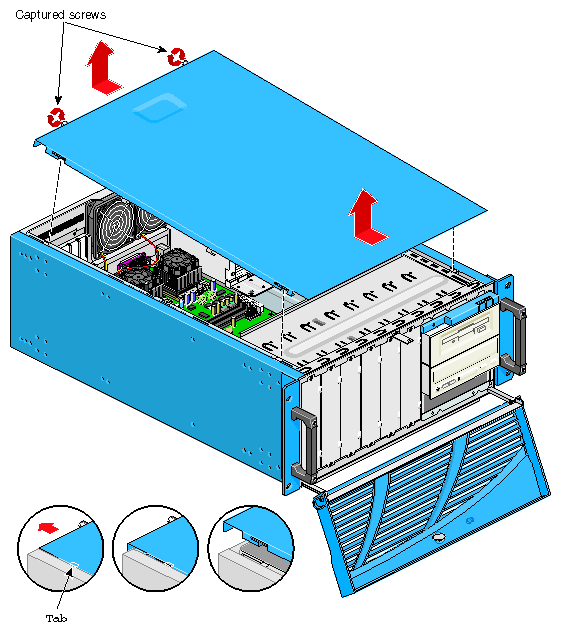
Loosen the two captive screws at the back of the node; see Figure 4-8.
Pull the node cover a centimeter or two (about half an inch) toward the back of the node; see Figure 4-8.
Lifting up on the back of the node cover, pull it up and away from the node; see Figure 4-8.
A node with a minimum complement of disk drives weighs about 14.5 kg (32 lbs).
| Note: Although each SGI Graphics Cluster node is usually under 15.5 kg (34 lbs) it is strongly recommended that a second person assist you in removing and adding nodes. |
To remove a node from a rack, follow these steps:
Locate a work surface that can accommodate the node.
If you are returning the node to Silicon Graphics, have ready the packaging for returning the node to Silicon Graphics. This packaging is available from SGI field service offices.
Warning: When adding or servicing equipment in the rack, do not pull out more than two nodes at a time. Pull the node out of the rack by following all the steps in “Pulling a Node Out of the Rack”.
If you are replacing the node immediately, you can leave the external SGI ImageSync cable connected to the next node. If you are not replacing the node immediately, connect the SGI ImageSync cable to the next node in the series. Remove and store the unused SGI Image Sync cable. The nodes of the SGI Graphics Cluster Series 12 must be daisy-chained for SGI_ImageSync to function.
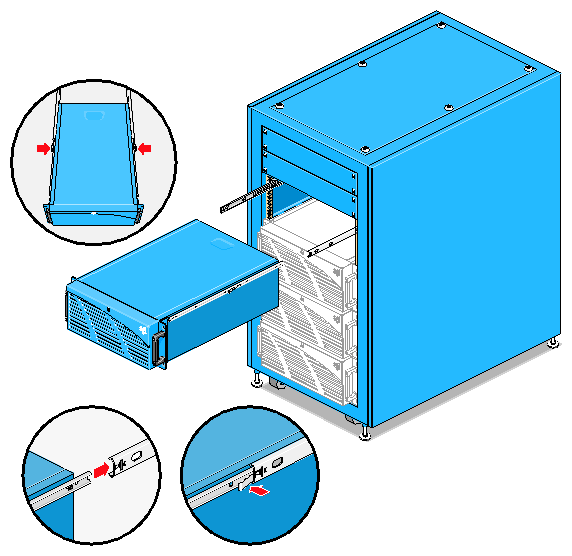
To extend the slide rails fully so that you can pull the node all the way out, use your thumbs to push in the levers on the rail at each side of the node as you pull out the node; see Figure 4-9.
Release the levers and pull the node forward off the slides; see Figure 4-9. Lift out the node and place it on the work surface.
If you are removing a node and not replacing it immediately, you can install a 4U node blanking plate in the rack; see Figure 4-10.
Blanking plates are available from SGI.
If you are replacing a node and have no slide rails for the new node, remove the slide rails to install on the replacement node. See “Attaching Sliders to a Node” for instructions.
Package the node and return it to SGI or your service provider.

For instructions on inserting a node into a rack, see “Adding a Node”.
This section explains:
For procedures in this section, you need the following:
#2 Phillips screwdriver
Nut driver
Note: These instructions require removal of the node from the rack. It is strongly recommended that a second person assist in removing and adding nodes to a rack.
To attach sliders to a node, follow these steps:
Have ready both three-part units of the slide rail pair and their hardware. Remove the inner part (slider) of each unit; set the bracket and outer part (slide rail) aside.
Note: If you are replacing a node, you can attach the sliders from the node you are replacing onto the replacement node. Remove the node from the rack by following the instructions in “Removing a Node from a Rack ”, and place it on a work surface.
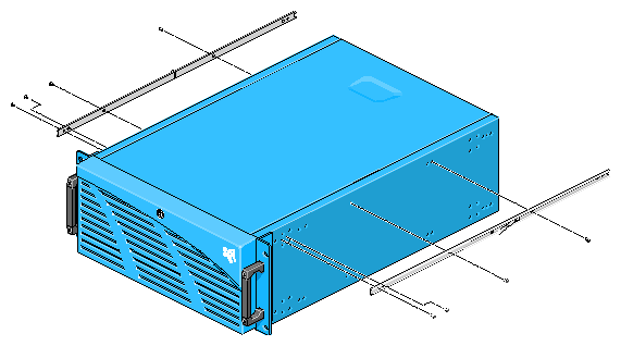
Starting at the front of the node chassis, align the first hole of the slider with the second hole of the chassis. Make sure the disconnect lever faces away from the system.
Secure each slider with screws, as shown in Figure 4-11.
To attach slide rails to a rack so that you can add a new node, follow these steps:
Have ready the two slide rails and their hardware, including the two brackets. The two inner parts (sliders) are attached to the node.
Prepare the rack as follows:
Power off the rack with its circuit breaker; unplug the rack.
If necessary for easier access, pull out the node that is next to the space where you want to attach the new slide rails. Pull out the rack's anti-tip shelf; see Figure 4-5.
Warning: Be sure to pull out the anti-tip shelf before pulling out a node. Failure to do so can result in the rack tipping over. Remove the screws that will interfere with the slide rails.
To accommodate a 4U node, measure 7 inches (12 holes).
Remove the screws from the inside holes on the rear rails, and replace them in the outside holes.
Tighten the top and bottom screws by hand and realign them. The outside of the front rail should be 69.8 cm (27.5 inches) to the outside of the back rail.
Torque the screws to 32 in-lbs.
Attach the slide rail mounting brackets to the slide rails, as follows.
Place two screws in the first and third holes on the front of the outer slide rail, and align the bracket so the screws protrude through the slotted hole on the bracket. Place the flat washer, lock washer, and nut on the screw.
Place two screws through the two holes on the back end of the slide rail, and align the bracket so the screws protrude through the slotted hole. Place a flat washer, lock washer, and nut on the screws.
Push both brackets towards the center of the slide rail so both outside screws are against the end of the slotted opening in the bracket. Use a nut driver and screwdriver to tighten the screws.
Repeat these steps for all slide rails needed (one set per system).
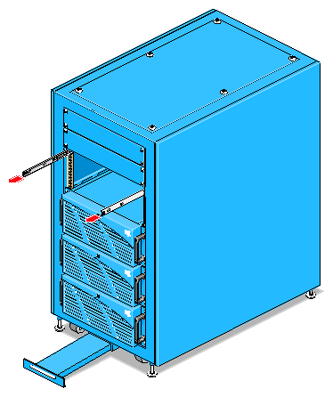
Install the slide rails in the rack, as follows (see Figure 4-12):
At the front of the rack, place a shoulder washer on four screws (10-32 x 3/8), align the slide to the proper rail holes, hold a clip nut on the backside of the slide, and place a screw (with shoulder washer) through the front of the rail.
Thread the screw into the clip nut until the shoulder washer engages the hole in the rail. Hold out and up on the slide while hand-tightening the screws.
Place the second screw the same way.
At the back of the rack, repeat these steps for the back of the slide.
Repeat for the other slide rail of the pair. When all slide rails are installed, torque all screws to 32 in-lbs. Do not overtighten the screws.
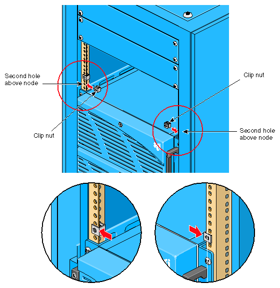
Install clip nuts, as follows:
Align the top hole of the clip nut on the inside of the rail with the second hole up from the slide.
Secure with one screw/shoulder washer and torque to 10 in-lbs.
Repeat for each slide on both sides of the rack. See Figure 4-13.
The lower hole of the clip nut is used later to secure the chassis to the rack.

A node with a minimum complement of disk drives weighs about 14.5 kg (32 lbs).
| Note: Although each SGI Graphics Cluster node is usually under 15.5 kg (34 lbs) it is strongly recommended that a second person assist you in removing and adding nodes. |
This section explains how to add a new node or install a replacement node, in these subsections:
For each node, make sure you have the following items:
One set of slide rails
The node's power cable
Ethernet cable for switch
SGI ImageSync daisy-chain cable for SGI Graphics Cluster Series 12 systems
Note: If you are replacing a node that was just removed, you can use the existing cabling.
To prepare a node for installation, follow these steps:
Attach sliders to the new node by following the instructions in “Attaching Slide Rails and Sliders”. If you are replacing a node, you can use the sliders from the node you are replacing.
Make sure all users have logged off the affected systems; power off each node in the rack.
Power off the rack with its circuit breaker; unplug the rack.
If you are adding a new node, remove the 4U node blanking plate at the front of the rack in the 4U space where the node will be placed. See Figure 4-14.
Note: The new node must be placed in the lowest available 4U space in the rack. If you are adding a new node and the rack does not yet have slide rails to accommodate the new node, install slide rails by following the instructions in “Attaching Slide Rails and Sliders”.
Pull out the rack's anti-tip shelf; see Figure 4-15.
Warning: Be sure to pull out the anti-tip shelf before pulling out a node. Failure to do so can result in the rack tipping over.
To install the node in the rack, follow these steps:
In the rack, push in the levers on each slide rail for the node and pull out each slide rail until it is fully extended, as shown in Figure 4-16. Make sure each slide rail is fully extended and locked into place.
Carefully align sliders at the rear of the node with the ends of the slide rails. After the node has been slid onto the rails, the node should latch onto them.
Note: Although the SGI Graphics Cluster nodes are under 15.5 kg (34 lbs), it is strongly recommended that a second person assist in this operation. Carefully begin pushing the node into the rack until the disconnect levers engage.
Release the disconnect levers and continue pushing the node into the rack until it is fully seated.
Secure the node to the rack chassis by screwing in the two screws at each side of the node. These screws are above and below each handle; they thread into clip nuts in the rack's slide rails. See Figure 4-17.
To cable the node in the system and attach its input and output peripherals, follow these steps:
For each node, make sure that you have on hand:
The node's power cable
Ethernet cable for the switch
SGI ImageSync daisy-chain cable for SGI Graphics Cluster Series 12 systems
Fiber optic cabling for optional gigabit Ethernet switch, if applicable
Cabling for peripherals, such as video cabling
Note: If you are replacing a node that was just removed, you can use the existing cabling.
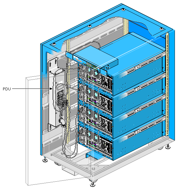
Attach the node's power cable to the rack's PDU; see Figure 4-18.
For a tall rack, place the node's power cable into the harness.

Caution: Do not turn on the node power at this time. Attach the node's daisy-chain (external) SGI ImageSync cable to the adjacent node. See Figure 4-19.
If you are replacing a master node, do the following:
Connect the keyboard and mouse.
Connect the Ethernet cable; plug the other end into a port on the rack's switch.
Connect the fiber optic cabling for the optional gigabit Ethernet switch, if applicable.
Connect the HD15 video cable to the system as shown in Figure 4-20.
Connect the monitor to the power source if it is not already connected.
Connect other peripherals as appropriate.
Note: Audio ports on the SGI Graphics Cluster motherboard are disabled.
USB port functionality is not supported in the SGI Graphics Cluster.
The S-VHS port on the graphics card is not supported.
Plug in the rack and turn it on with the circuit breaker on the PDU. Push in the anti-tip shelf.
Turn on the master node by pressing the power button on the front panel (see Figure 4-2). Turn on each channel node.
Follow the instructions in Chapter 3, “SGI Graphics Cluster Administration” and also in system software manuals, as needed, to configure the node and reconfigure the system.

The system switch and the optional gigabit Ethernet switch must be inserted into the rack at an angle to get past the rack rear door. Therefore, if the rack has the full complement of channel nodes, you must remove the top node to make room to insert the switch(es). An alternative is to remove the door; see “Removing the Rack Rear Door ”.
| Note: To install an optional gigabit Ethernet switch, an additional person is required. |
To replace or add a network switch, follow these steps:
Make sure all users have logged off the affected systems. Power off the nodes. Power off the rack with its circuit breaker.
Pull out the anti-tip shelf; see Figure 4-15.
Warning: Be sure to pull out the anti-tip shelf before pulling out a node. Failure to do so can result in the rack tipping over. If the rack has the full complement of channel nodes, remove the top node to make room to insert the switch; follow steps in “Removing a Node from a Rack ”. This step is necessary because the Ethernet switch included with the system must be inserted at an angle. An alternative is to remove the door; see “Removing the Rack Rear Door ”.
If you are replacing the system Ethernet switch and an optional gigabit Ethernet switch is present, you might need to remove optical cables to access the system Ethernet switch.
If you are adding or replacing an optional gigabit Ethernet switch, remove the Ethernet switch included with the system. This step is necessary because the gigabit Ethernet switch must be inserted at an angle. Follow these steps:
Disconnect the cables from the system Ethernet switch. Disconnect the switch power cable, which is routed around the side of the rack, between the rack rails and the rack chassis wall. You can leave these cables in place and connected at their other ends.
Unscrew the rack mount screws that hold the system Ethernet switch to the rack rails.
Remove the switch from the rack.
Route the power cord for the new switch between the rack rails and the rack chassis wall, and plug it into the PDU.
If you are adding a gigabit Ethernet switch, install it in the rack:
Remove the two 2U panels at the front of the rack.
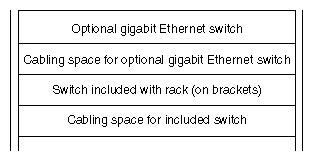
Angle the switch into the rack and place it in the top 1U space in the rack; see Figure 4-21.
With a second person holding the switch in position, bolt the mounting brackets on the rear of the gigabit Ethernet switch to the rack rails.
Reinsert the original system switch in the third 1U space from the top of the rack. Secure it to the rack rails. Recable it.
Attach the power cords to the switch(es).
Cable the nodes to the new switch.
If the top node was removed, replace it and cable it.
Replace the two 2U panels on the front of the rack, if you have removed them. Replace the rear door, if you have removed it.
Power on both switches.
Power on the nodes; power on the rack. Push in the anti-tip shelf.
If you have not already done so, configure the network IP and host settings.
Follow instructions in the switch manual for switch configuration.
Removing the rear door on the short or tall rack can facilitate switch installation or replacement, especially where the door cannot be opened fully.
The rack rear door has lift-off hinges and a quick disconnect terminal on the door end of the ground wire. To remove the door, follow these steps:
Open the door to the 90 degree position.
Disconnect ground wire from door.
Lift the door straight up off the hinges.
For a tall rack, you can lift up on the bottom of the door with the top of your foot.
When you reinstall the door, do not forget to reattach the ground wire.