The HD I/O Board supports the Video Library (VL). This API is described in the Digital Media Programming Guide (007-1799-060 or later; hereafter referred to as the DMPG).
This chapter consists of the following sections:
To build programs that run under VL, you must
install the dmedia_dev and dmedia_eoe options
link with libvl
include dmedia/vl.h and dmedia/vl_xthd.h for device-dependent functionality
The client library for VL is /usr/lib32/libvl.so. The header files for the VL are in /usr/include/dmedia; the main file is vl.h. This file contains the main definition for the VL API and has controls that are shared by all hardware. You can find several useful digital media programming examples in /usr/share/src/dmedia/video/XTHD.
For more information on the Video Library and using the API, see the latest version of the DMPG.
The following topics are covered in this section:
The Video Library defines a basic set of primitives and mechanisms that specify interconnections and controls for the desired setup. The following concepts are central to VL:
path: an abstraction that describes the way data moves around
-
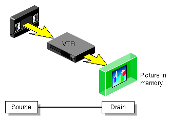
The basic nodes are a source (such as a VTR) and a drain (such as memory). The example in Figure 2-1 shows one source node and one drain node, which illustrates the simplest VL path.
The HD I/O Board has a video source node (the video input), a video drain node (the video output), a memory source node (for output from application), and a memory drain node (for input to application). For transfers, each path must contain exactly one video node and one memory node. HD I/O nodes are further discussed in “VL Nodes for the HD I/O Board ”.
VL syntax elements are as follows:
The VL recognizes these classes of objects:
nodes, which are sources, drains, and internal nodes (as discussed in the preceding section)
paths, connecting sources and drains (as discussed in the preceding section)
buffers, for sending and receiving field/frame data to and from host memory
The HD I/O Board requires the use of DMbuffers (digital media buffers). DMbuffers, an abstraction of main memory, allow efficient and API-independent interchange of data between the different digital media libraries. For example, video fields can be captured into DMbuffers via VL and then displayed in graphics using OpenGL. They can also be passed between two processes without the data having to be copied explicitly. For details, refer to Chapter 5, “Digital Media Buffers,” in the DMPG.
events, for monitoring video I/O status
controls, or parameters that modify how data flows through nodes; for example:
video device parameters, such as sync source
video data parameters such as packing, size, and color space
Following are the two types of VL controls:
Using the HD I/O Board with both types of VL controls is explained later in this chapter.
Use vlGetNode() to specify nodes. This call returns the node's handle, which is used when setting controls or setting up paths. Its function prototype is:
VLNode vlGetNode(VLServer svr, int type, int kind, int number) |
In this prototype, variables are as follows:
VL_ANY can also be used as a value for number to reference the first available node of the specified type and kind.
In general, a path for the HD I/O Board has a memory node and a video node. The following fragment creates a digital video input source node and a memory drain node, and creates the path:
VLServer svr;
VLPath path;
VLNode src;
VLNode drn;
                     /*Set up video source node */
src = vlGetNode(svr, VL_SRC, VL_VIDEO, VL_ANY);
                     /*Set up memory drain node */
drn = vlGetNode(svr, VL_DRN, VL_MEM, VL_ANY);
                     /* Create source-to-drain path */
if((path = vlCreatePath(svr, VL_ANY, src, drn)) < 0){
     fprintf(stderr,”%s\n”,vlStrError(vlGetErrno()));
     exit(1);
}
                     /* Set up path with shared src and drn node */
vlSetupPaths(svr, (VLPathList)&path, 1, VL_SHARE, VL_SHARE);
|
After you specify the nodes, use vlSetControl() to specify the parameters as follows:
For memory nodes, you must set packing, color space, size, and capture type
For video nodes, if desired, set video timing, format (for example digital component), and color space; otherwise, the default values displayed in the video control panel (vcp) are applied
Controls for each node are defined in “HD I/O Controls”, and are summarized in Table 2-2. You can set controls in any order.
This section summarizes VL data transfer categories, and provides basic instructions for creating an application. For the HD I/O Board, VL data transfers always involve memory (video to memory, memory to video), which requires a DMbuffer pool setup.
Follow these steps to create a VL application using the VL programming model:
Open a connection to the video daemon (vlOpenVideo()).
Specify nodes on the data path (vlGetNode()).
Create the path (vlCreatePath()).
Optional step: add more nodes to a path (vlAddNode()).
Set up the hardware for the path (vlSetupPaths()).
Specify path-related events to be captured (vlSelectEvents(), vlAddCallback()).
Set input and output parameters (controls) for the nodes on the path (vlSetControl()).
Video format and timing set in the vcp are persistent and default to reasonable values.
Create a dmBuffer pool to hold data for memory transfers (vlDMGetParams(), dmBufferSetPoolDefaults(), dmBufferCreatePool(), vlGetTransferSize()).
Register the buffer (vlDMPoolRegister(),vlDMPoolDeregister()).
Start the data transfer (vlBeginTransfer()).
Get the data (vlDMBufferGetValid(), vlDMBufferPutValid(), dmBufferAllocate(), dmBufferAllocateSize(), dmBufferGetPoolState(), dmBufferGetPoolFD(), dmBufferSetPoolSelectSize(), dmBufferMapData(), dmBufferFree()) to manipulate frame data.
Handle data stream events (vlSelectEvents(), vlNextEvent(), vlPending()).
Clean up (vlEndTransfer(), vlDMPoolDeregister(), vlDestroyPath(), vlCloseVideo()).

Note: Error handling (vlPerror()) is accomplished throughout.
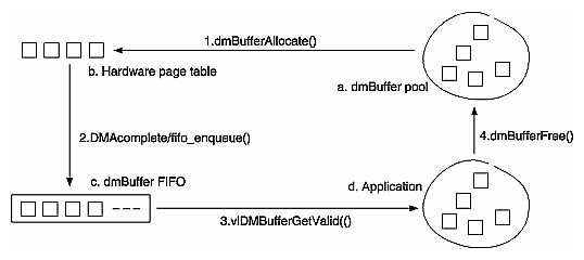
The diagram in Figure 2-2 shows the input data flow.
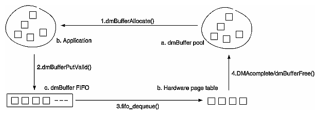
The diagram in Figure 2-2 shows the output data flow.
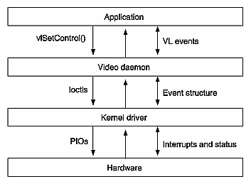
The diagram in Figure 2-4 shows the control flow.
This section covers the following topics:
After you set up a path, and before you start a transfer, you must configure the memory and video nodes appropriately. Controls on the video node are persistent; that is, they retain their values between path destruction and creation. Memory node controls, however, are reset at each path creation. Because the video node controls are persistent, they need not be set by an application that can deal with arbitrary settings.
For a memory node, you must set the following controls because the default values are likely to be inappropriate:
VL_PACKING
VL_COLORSPACE
VL_CAP_TYPE
VL_SIZE
The recommended way to set VL_SIZE is to query VL_SIZE on the video node (after setting VL_TIMING appropriately) and use the returned value to set VL_SIZE on the memory node.
On the video node, applications will probably need to set some controls as well. Most of them can also be set with the video control panel application (vcp).
To determine the available devices (that is, video options in the workstation, such as the HD I/O Board) and the nodes available on them, run vlinfo. To determine possible controls for each device, enter
vlinfo -l |
| Note: VL controls specified as true with vlSetControl() are executed immediately. However, they do not necessarily occur at a specific time. |
To set controls for HD I/O nodes, use vlSetControl(). The following example sets video format and timing on a node:
For details on vlSetControl() and vlGetControl(), see the latest version of the DMPG.
Table 2-1 summarizes node controls for the HD I/O Board.
Table 2-1. HD I/O Node Controls
Control | Video Source | Memory Source | Video Drain | Memory Drain |
|---|---|---|---|---|
| X |
| X | |
X (YCrCb and RGB_H only) | X | X YCrCb and RGB_H only) | X | |
X |
| X |
| |
X |
| X |
| |
|
| X |
| |
X (read only) | X | X (read only) | X | |
| X |
| X | |
X (read only) | X | X (read only) | X | |
|
| X |
| |
X |
| X |
| |
X |
| X |
| |
|
| X |
| |
| X | X |
| |
X |
| X |
| |
X |
|
|
| |
X |
|
| X | |
| X |
| X |
| Note: Except for VL_XTHD_VITC_LINE_OFFSET, VL_H_PHASE, and VL__VPHASE, none of the controls can be changed during a transfer. |
Table 2-2 summarizes the values and uses of controls for the HD I/O Board.
Table 2-2. Controls for the HD I/O Board
Control | Values or Range | Use |
|---|---|---|
VL_CAPTURE_INTERLEAVED | Selects type of frame(s) or field(s) to capture. See “VL_CAP_TYPE ” in this chapter. | |
VL_COLORSPACE_REC601_YCRCB | Specifies color space of video data in memory or for input/output. See “VL_COLORSPACE ” in this chapter. | |
VL_F1_IS_DOMINANT
Note: Output frames are deinterlaced differently depending on the choice of output field dominance. Deinterlacing is specified in the application. | Identifies frame boundaries in a field sequence (interlaced formats); ignored by progressive timings. in this chapter. | |
VL_FORMAT_DIGITAL_COMPONENT_DUAL | Specifies sampling format of data in or
out:
4:2:2:4 or 4:2:2, depending on packing. in this chapter. | |
[-1000,1000] pixels (increment of 1) | Sets horizontal phase. | |
Sets the position within the video raster to (0,0). | ||
Sets packing format for memory source or drain node. See “VL_PACKI NG ” and Appendix C, “Pixel Packings and Color Spaces ” . | ||
Memory: Sets size of the desired region of the video raster, which must be the same as the default active region. Video: Returns size of video raster (frame); dependent on timing. | ||
Sets sync mode for video output; see “VL_SYNC ” . | ||
VL_SYNC_HOUSE | Selects the genlock source if VL_SYNC_GENLOCK is used. VL_SYNC_HOUSE is analog reference. VL_XTHD_SYNC_DIGITAL_INPUT | |
VL_TIMING_1125_1920x1080_5994p | Sets or gets timing; see “VL_TIMING ” . | |
[-600,600] lines (increment of 1) | Sets vertical phase. | |
VL_XTHD_EE_MODE_OFF | Causes digital output to transmit a copy of digital input data; output must be genlocked. | |
VL_XTHD_INTERFACE_PRECISION_8 | Specifies whether external video interface is 8 bits or 10 bits wide. | |
TRUE | For video source only, sets video input to the output pipe rather than the input jack (TRUE). | |
VL_XTHD_OUTPUT_REPEAT_DISABLED | Controls whether system repeats DMbuffers output is underflowing; see “Automatically Correcting for Output Underflow ” . | |
1, -1 | Sets position of top video line in the buffer; see “VL_ ZOOM ” . |
The VL_TIMING control sets timing type, which expresses the timing of video presented to a source or drain.
| Note: For the HD I/O Board, VL_TIMING is specified on the video node only, and not on the memory mode, as with other Silicon Graphics video options. |
Table 2-3 lists output timings for various inputs.
Table 2-3. Supported Output Timings for Inputs or Reference Sources
Input/Reference Source (Sync Source) | Output Timing | VL_TIMING |
|---|---|---|
525_NTSC | [email protected] | 1920x1080_5994i |
625_PAL | 1920x1080i@50Hz | 1920x1080_50i |
[email protected] | 1920x1080_5994i | |
[email protected] | 1920x1080_2398p | |
[email protected] | 1920x1080_2398p | |
1920x1080p24Hz | 1920x1080p24Hz | 1920x1080_24p |
1920x1080PsF24Hz | 1920x1080p24Hz | 1920x1080_24p |
1920x1080i@50Hz | 1920x1080i@50Hz | 1920x1080_50i |
[email protected] | 1920x1035_5994i | |
[email protected] | 1920x1080_5994i | |
1920x1080p25Hz | 1920x1080p25Hz | 1920x1080_25p |
1920x1080PsF25Hz | 1920x1080p25Hz | 1920x1080_25p |
Each value for VL_TIMING indicates the raster configuration of a particular SMPTE specification, such as SMPTE 274M-1995 system 3. The values are named according to the raster format:
The first field is the number of total lines, such as 1125, 750, 525, or 625.
The second field is the size of the active region, in pixels by lines.
The third field is the vertical refresh rate and the scanning format; the scanning format is
For example, VL_TIMING_1125_1920x1080_5994i specifies 1125 total lines, an active region of 1920 pixels by 1080 lines, 59.94 fields per second, and 2:1interlacing.
| Note: Although the VL defines timings with sampling rates up through 148.5 MHz, the HD I/O Board supports only those through 74.25 MHz. |
The HD I/O Board has flexible sync and genlock controls. You can select sync for the outputs only; inputs sync only to the sync and clock information embedded in the digital input stream.
You can configure the video output to lock to an external sync source (genlock) or to free run (stand-alone). The VL_SYNC control allows you to select stand-alone mode or one of the genlock modes. If the setting is genlock, the following sync sources are available:
Bilevel sync sources: external 525 NTSC, 625 PAL
These choices select the analog composite video signal present on the connector labeled GEN IN. Be sure to terminate the loop-through connector (GEN OUT). For more information, see “Setting Up External Sync” in Appendix B in Appendix B, “Setting Up the HD I/O Board for Your Video Hardware”.
Trilevel sync sources: external 1920x1080_5994i, 1920x1080_50i, 1920x1080_25p, 1920x1080_24p, 1920x1080_2398p, 1920x1035_5994i, 1920x1080_24PsF, 1920x1080_2398PsF, 1920x1080_25PsF
These choices select the analog composite or component (Y or G) video signal present on the connector labeled GEN IN. Be sure to terminate the loop-through connector (GEN OUT). For more information, see “Setting Up External Sync” in Appendix B in Appendix B, “Setting Up the HD I/O Board for Your Video Hardware”.
For valid sync source/timing genlock combinations, see Table 2-3. Only these combinations are supported.
The VL_FORMAT control is used on video nodes only. It specifies the sampling format of data on the wire, specifically, dual-link (4:4:4 or 4:4:4:4) or single-link (4:2:2).
VL_FORMAT_DIGITAL_COMPONENT_DUAL: either 4:4:4 or 4:4:4:4, depending on the specified packing
VL_FORMAT_DIGITAL_COMPONENT: Standard YCrCb color space sampled at 4:2:2.
The memory packing mode VL_PACKING determines how components are actually sampled.
VL_FORMAT does not imply color space, nor does it imply whether the second link is used. The second link is used whenever alpha/key channel is used, which depends on the VL_PACKING setting, or when color is sampled at 4:4:4.
A video packing describes how a video signal is stored in memory, in contrast to a video format, which describes the characteristics of the video signal. For example, the memory source node accepts packed video from a DMbuffer and outputs video in a given format. Packings are specified through the VL_PACKING control on the memory nodes.
| Note: Because of HDTV's multiple color spaces, “old style” packings, such as VL_PACKING_Y_8_P, are ambiguous and therefore no longer supported for the HD I/O Board. You must specify the packing and color space explicitly. |
The HD I/O Board supports common packings up through 32 bits per pixel, including 4:4:4, 4:2:2, and 4:4:4:4, at 8, 10, and 12 bits per component. Specifically, it supports packings compatible with OpenGL and IRIS GL, and those in common use from other video products. Appendix C, “Pixel Packings and Color Spaces ” shows the layout of each packing for the HD I/O Board. It also provides the corresponding names for these packings that are used by other libraries.
An application must set both VL_PACKING and VL_COLORSPACE. Note that changes in one parameter may change the values of other parameters set earlier; for example, clipped size may change if VL_PACKING is set after VL_SIZE. For example:
VLControlValue val; val.intVal = VL_PACKING_444_8; vlSetControl(vlSvr, path, memdrn, VL_PACKING, &val); |
| Note: At the beginning of a data transfer, it takes several seconds to activate a change in this control. |
The VL_COLORSPACE control specifies the color space of video data in memory or for input and output. A color space is a color component encoding format, for example, RGB and YUV. Because video equipment uses more than one color space, the HD I/O video nodes, in addition to the memory nodes, support the VL_COLORSPACE control.
Each component of an image has
a color that it represents
a canonical minimum value
a canonical maximum value
Normally, a component stays within the minimum and maximum values. For example, for a luma signal such as Y, you can think of these limits as the black level and the peak white level, respectively. For an unsigned component with n bits, there are two possibilities for [minimum value, maximum value]:
Various HDTV specifications define color models differently from those defined in Recommendation 601 ( ITU-R BT.601), which is used by most standard-definition digital video equipment. For HDTV, the VL defines three color models:
Within each color model, four different color spaces exist:
-
Headroom range means that black is at, for example, code 64 rather than 0, and white is at, for example, code 940 rather than 1023. Headroom-range color spaces can accommodate overshoot (superwhite) and undershoot (superblack) colors. Full-range color spaces clamp these out-of-range colors to black and white.
For memory nodes, these four color spaces are defined for each of three color models, resulting in 12 color spaces. Note that all 12 are supported on memory nodes, but only YCrCb and RGB_H color spaces are supported on video nodes.
Table 2-4 summarizes currently supported combinations of VL_FORMAT and VL_COLORSPACE; future releases will support more combinations. For detailed information on supported combinations, refer to the XTHD MAN pages and release notes regarding “Color Representations.”
Table 2-4. VL_FORMAT and VL_COLORSPACE Combinations Supported
Video Node | Memory Node |
|---|---|
4:2:2 YCrCb | 4:4:4 RGB_F |
4:2:2 YCrCb | 4:4:4 RGB_H |
4:2:2 YCrCb | 4:2:2 YCrCb |
4:4:4YCrCb | 4:4:4 YCrCb |
4:4:4 RGB_H | 4:4:4 RGB_H |
Color-space conversion is performed within a color model if the color spaces are different on the memory and video nodes. Conversion between the color models is not supported.
| Note: Changing this control at the beginning of data transfer takes several seconds to go into effect. |
Typically, two sets of colors are used together, RGB ( RGBA) and YCrCb /YUV ( VYUA). YCrCb ( YUV), the most common representation of color from the video world, represents each color by a luma component called Y and two components of chroma, called Cr (or V), and Cb (or U). The luma component is loosely related to brightness or luminance, and the chroma components make up a quantity loosely related to hue. These components are defined in ITU-R BT.601 (also known as Rec. 601 and CCIR 601), ITU-R BT.709-2, and SMPTE 240M.
The alpha channel is not a real color. For that channel, the minimum value means completely transparent, and the maximum value means completely opaque.
For OpenGL, IRIS GL, and DM:
the library constant indicates whether the data is RGBA or VYUA
RGBA data is full-range by default
VYUA data in DM can be full-range or compressed-range; you must determine this from context
For more information about color spaces, see A Technical Introduction to Digital Video, by Charles A. Poynton (New York: Wiley, 1996).
Along with memory node color space, VL_COLORSPACE determines the color-conversion matrix values. In addition, this control affects the type of blanking output by the board during horizontal and vertical blanking, and during active video area when not transferring data. On a video drain node, VL_COLORSPACE affects the type of blanking that the board outputs, in accordance with SMPTE 274M:
YCrCb: blanking is Y = 64, Cr/Cb = 512, A = 64
RGB_H: blanking is R = 64, G = 64, B = 64, A = 64
The HD I/O Board supports lookup tables (LUTs) on input and output for gamma correction or decorrection. To successfully run an application with linear components, you can use LUTs to convert between linear and nonlinear spaces.
The HD I/O hardware includes a separate LUT for each RGB color component. Each of the three LUTs is a table of 8192 entries; each entry stores 13 bits. The application programs the entries in each table. The LUTs produce offsets, if they are required by the memory storage format.
The LUTs perform rounding as follows:
If the LUT is not explicitly programmed by the application, the output LUT is in pass-through mode, all rounding is performed in the color-space converter and the input LUT performs both rounding and offset.
If the LUT is programmed explicitly by the application, the application can control rounding as part of the lookup table function. The packer (hardware that reads the LUT and formats data for the host memory; see Figure 1-2) performs a final conversion from 13-bit LUT format to host memory format.
It is also possible for an application to use the LUT to convert between video node RGB_H and memory node RGB_F. Because each component is independent of the others for this conversion, a matrix multiplication is not needed (pass through mode). The required component scaling and rounding can be placed into each LUT.
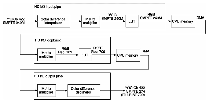
Figure 2-5 and Figure 2-6 show examples of color-space conversions.
In the examples, RGB are values in linear space and R'G'B' are values in nonlinear space after the optoelectric transfer function is applied as specified in ITU-R BT.709. You can use the LUTs to apply this function or its inverse to convert between RGB and R'G'B'.
The example in Figure 2-5 shows a typical video capture path. In this example, the input jack is YCrCb 4:2:2 and the desired result in system memory is RGB. First, an appropriate filter interpolates YCrCb 4:2:2 to YCrCb 4:4:4 to fill in the missing CrCb samples. Then a 3x3 matrix multiplier with appropriate offsets and coefficients obtains RGB values for each pixel. At this point, you can use the LUT option to convert gamma pre-corrected RGB values to linear RGB values. Finally, the packer swizzles the bits into the desired memory packing format and DMA places the result in system memory.

Figure 2-6 summarizes a complicated conversion between color spaces for 4:2:2 sampling rates and different primary colors. The example shows the conversion of material produced using SMPTE 240M colorimetry to material in SMPTE 274M format (ITU-R BT.709.2 colors).
An application can request that the HD I/O Board capture or play back a video stream in a number of ways. For example, the application can request that each field be placed in its own buffer, or that each buffer contain an interleaved frame. This section describes the capture types supported by the HD I/O Board.
Supported capture types are as follows:
VL_CAPTURE_NONINTERLEAVED
VL_CAPTURE_INTERLEAVED
VL_CAPTURE_FIELDS is equivalent to VL_CAPTURE_NONINTERLEAVED. The HD I/O Board does not support VL_CAPTURE_EVEN_FIELDS and VL_CAPTURE_ODD_FIELDS.
| Note: VL_SIZE refers to the size of each frame, rather than the size of the buffer in memory, so it is independent of VL_CAP_TYPE; the VL_CAP_TYPE setting does not change VL_SIZE. |
The VL_CAPTURE_NONINTERLEAVED capture type specifies that frame-size units are captured noninterleaved. Each field is placed in its own buffer, with the dominant field in the first buffer. If one of the fields of a frame is dropped, all fields are dropped. Consequently, an application is guaranteed that the field order is maintained; no special synchronization is necessary to ensure that fields from different frames are mixed.
If you specify VL_CAPTURE_NONINTERLEAVED for playback, similar guarantees apply as for capture. If one field is lost during playback, it is not possible to “take back” the field. The HD I/O Board resynchronizes on the next frame boundary, although black or “garbage” video might be present between the erring field and the frame boundary.
Interleaved capture interleaves the two fields of a frame and places them in a single buffer; the order of the fields depends on the value set for VL_DOMINANCE_FIELD. The HD I/O Board guarantees that the interleaved fields are from the same frame: if one field of a frame is dropped, then both are dropped.
During playback, a frame is deinterleaved and output as two consecutive fields, with the dominant field output first. If one of the fields is lost, the HD I/O Board resynchronizes to a frame boundary before playing the next frame. During the resynchronization period, black or “garbage” data may be displayed.
VL_SIZE refers to the size of each frame, rather than the size of the buffer in memory, so it is independent of VL_CAP_TYPE; the VL_CAP_TYPE setting does not change VL_SIZE.
For memory nodes, VL_SIZE specifies the desired region of the video raster, which must be the same as the default active region. There is no default; this control must be set. On video nodes, this control is read-only and cannot be set.
For memory nodes, VL_OFFSET is related to VL_SIZE; it specifies the origin of the video region to be captured at (0,0), the standard beginning of active video. The recommended way to set VL_SIZE for the memory node is to query it on the video node (after setting VL_TIMING appropriately) and use the returned value to set VL_SIZE on the memory node.
The VL_ZOOM control specifies the site of the top video line in memory; it does not scale (zoom and decimate) a video image as for some other Silicon Graphics video options. The VL_ZOOM value can be 1 or -1:
1: Normal line order; the top video line is at the lowest address in the buffer.
-1: Inverted line order; as in OpenGL, the top video line is at the highest address in the buffer.
Field dominance identifies the frame boundaries in a field sequence; that is, it specifies which pair of fields in a field sequence constitute a frame. The control VL_FIELD_DOMINANCE allows you to specify whether an edit occurs on the nominal video field boundary (Field 1, or F1) or on the intervening field boundary (Field 2, or F2).
F1 dominant: The edit occurs on the nominal video field boundary.
F2 dominant: The edit occurs on the intervening field boundary.
Whether a field is Field 1 or Field 2 is determined by the setting of bit 9, the F bit, in the XYZ word of the EAV and SAV sequences. This setting is defined as follows:
For Field 1 (also called the odd field), the F bit is 0.
For Field 2 (also called the even field), the F bit is 1.
Note: Field dominance has no effect on progressive timings.
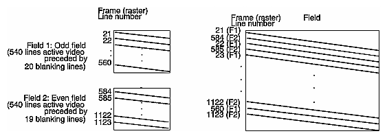
Figure 2-7 shows fields and frames as defined for digital 1080-line formats for the HD I/O Board.
Editing is usually on Field 1 boundaries, where Field 1 is defined as the first field in the video standard's two-field output sequence. However, some users may want to edit on F2 boundaries, which fall on the field in between the video standard's frame boundary. To do so, use this control, then program your deck to select F2 edits.
A set of frames to be output must be deinterlaced into fields differently, depending on the choice of output field dominance: for SMPTE 274M, the top line is in F1, as shown in Figure 2-7; for SMPTE 240M, the top line is in F2. For example, when F1 dominance is selected, the field with the topmost line must be the first field to be transferred; when F2 dominance is selected, the field with the topmost line must be the second field to be transferred.
If the application is not sending buffers fast enough for the receiving equipment's video frame rate, you can set VL_XTHD_OUTPUT_REPEAT to repeat DMbuffers automatically. The values for this control vary, depending on whether the transfer is progressive or interlaced.
For interlaced noninterleaved transfers, choices are as follows:
VL_XTHD_OUTPUT_REPEAT_LAST_FIELD
This setting repeats the last buffer twice. This setting is spacially imperfect, but does not cause flicker.
VL_XTHD_OUTPUT_REPEAT_LAST_FRAME (the default)
This setting repeats the last pair of buffers. This setting is spacially better than VL_XTHD_OUTPUT_REPEAT_LAST_FIELD, but causes flicker.
VL_XTHD_OUTPUT_REPEAT_DISABLED
This setting, which does not resend any data, is the most useful for debugging, since underflow is then quite visible on output.
For progressive or interleaved transfers, choices are as follows:
VL_XTHD_OUTPUT_REPEAT_LAST_FRAME (the default)
This setting repeats the last buffer.
VL_XTHD_OUTPUT_REPEAT_DISABLED
To capture graphics to video, you can use OpenGL to read pixels into memory. However, the coordinate system differs between video and Open GL; under OpenGL, the origin is at the lower left corner and in video, origin is in the upper left corner. To adjust for this difference, set VL_ZOOM to -1; see “VL_ ZOOM ”.
The VL provides several ways of handling data stream events, such as completion or failure of data transfer, vertical retrace event, loss of the path to another client, lack of detectable sync, or dropped fields or frames. The method you use depends on the type of application you are writing:
For a strictly VL application, use
vlSelectEvents() to choose the events to which you want the application to respond
vlCallback() to specify the function called when the event occurs
your own event loop or a main loop (vlMainLoop()) to dispatch the events
For an application that also accesses another program or device driver, or if you are adding video capability to an existing X or OpenGL application, set up an event loop in the main part of the application and use the IRIX file descriptor (FD) of the event(s) you want to add.
For more information on these functions, see Chapter 4 in the DMPG.
Table 2-5 summarizes events for the HD I/O Board. For these options, this table supersedes the table of events in Chapter 14, “VL Event Handling,” in the DMPG; the HD I/O Board supports only the events listed in Table 2-5.
Event | Use |
|---|---|
VLSyncLost | Sync is not detected |
VLStreamStarted | Stream started delivery |
VLStreamStopped | Stream stopped delivery |
VLSequenceLost | A field/frame was dropped |
VLControlChanged | A control on the path has changed |
VLTransferComplete | A field/frame transfer has completed |
VLTransferFailed | A transfer has failed and DMA is aborted |
VLTransferError | A transfer error was discovered; field may be invalid |
The DMediaInfo structure reports the Unadjusted System Time (UST).
The HD I/O Board makes use of the error events noted in Chapter 4 of the DMPG, as well as VLTransferErrorEvent, which reports nonfatal video transfer errors. The VLTransferComplete and VLSequenceLost events also report the Media Stream Count ( MSC) of the field or frame transferred or failed.
This section contains three examples:
This example shows an application that simply captures video data and records it to disk, for later playout. The video is left in its original 4:2:2 sampling and color space. Because 10 bits are required, the R242_10 packing mode is chosen. Frames start on F1 boundaries. After creating the VL path, the application sets up the video node, mostly as a result of user input, since it depends on external equipment.
videoSource.VL_TIMING = VL_TIMING_1125_1920x1080_5994i videoSource.VL_COLORSPACE = VL_COLORSPACE_REC709_YCRCB videoSource.VL_FIELD_DOMINANCE = VL_F1_IS_DOMINANT videoSource.VL_FORMAT = VL_FORMAT_DIGITAL_COMPONENT videoSource.VL_XTHD_LOOPBACK = VL_XTHD_LOOPBACK_OFF videoSource.VL_XTHD_INTERFACE_PRECISION = VL_XTHD_INTERFACE_PRECISION_10 |
Next, the application configures memory node:
memoryDrain.VL_SIZE = videoSource.VL_SIZE memoryDrain.VL_COLORSPACE = videoSource.VL_COLORSPACE memoryDrain.VL_CAP_TYPE = VL_CAPTURE_NONINTERLEAVED memoryDrain.VL_PACKING = VL_PACKING_R242_1 |
Next, the application calls vlGetTransferSize() to get the required buffer size to hold each field. Using that size, it creates and registers a DMS buffer pool and starts the transfer.
This example shows an application that plays back data captured in the previous example.
The application in the previous example stored various attributes along with the data, including color space, frame rate, dominance, and size. These attributes, along with some user-specified options, are used to derive the control values. After creating the VL path, the application sets up the video node:
videoDrain.VL_TIMING = VL_TIMING_1125_1920x1080_5994i videoDrain.VL_COLORSPACE = VL_COLORSPACE_REC709_YCRCB videoDrain.VL_FIELD_DOMINANCE = VL_F1_IS_DOMINANT videoDrain.VL_FORMAT = VL_FORMAT_DIGITAL_COMPONENT videoDrain.VL_XTHD_INTERFACE_PRECISION = VL_XTHD_INTERFACE_PRECISION_10 videoDrain.VL_SYNC = VL_SYNC_GENLOCK videoDrain.VL_SYNC_SOURCE = VL_XTHD_SYNC_HOUSE |
Next, the application configures the memory node:
memorySource.VL_SIZE = videoDrain.VL_SIZE memorySource.VL_COLORSPACE = videoDrain.VL_COLORSPACE memorySource.VL_CAP_TYPE = VL_CAPTURE_NONINTERLEAVED memorySource.VL_PACKING = VL_PACKING_R242_10 |
Next, the application calls vlGetTransferSize() to get the required buffer size to hold each field. Using that size, it creates a DMS buffer pool, allocates, fills, and prequeues some buffers, and starts the transfer.
In this example, the application captures video and draws it on the graphics screen using OpenGL. This example resembles the videoin application.
The incoming video is converted to 10-bit 4:4:4 full-range RGB in an OpenGL-compatible packing format. The 4444_10_10_10_2 packing is chosen; it is compatible with OpenGL using packed-pixel extension GL_UNSIGNED_INT_10_10_10_2_EXT pixel format. Video is interleaved in memory into frames, and is written upside down to be compatible with OpenGL's default coordinate system (glPixelZoom of (1.0, 1.0)).
First, the video node is configured:
videoSource.VL_TIMING = VL_TIMING_1125_1920x1080_5994i videoSource.VL_COLORSPACE = VL_COLORSPACE_REC709_YCRCB videoSource.VL_FIELD_DOMINANCE = VL_F1_IS_DOMINANT videoSource.VL_FORMAT = VL_FORMAT_DIGITAL_COMPONENT videoSource.VL_XTHD_LOOPBACK = VL_XTHD_LOOPBACK_OFF videoSource.VL_XTHD_INTERFACE_PRECISION = VL_XTHD_INTERFACE_PRECISION_10 |
Next, the application configures memory node:
memoryDrain.VL_SIZE = videoSource.VL_SIZE memoryDrain.VL_COLORSPACE = VL_COLORSPACE_REC709_RGB_F memoryDrain.VL_CAP_TYPE = VL_CAPTURE_INTERLEAVED memoryDrain.VL_PACKING = VL_PACKING_4444_10_10_10_2 memoryDrain.VL_ZOOM = -1/1 |
Next, the application calls vlGetTransferSize() to get the required buffer size to hold each field. Using that size, it creates and registers a DMS buffer pool and starts the transfer.