This appendix shows you how to attach video equipment to the HD I/O Board front panel connectors and how to use the video control panel vcp to set the board to match your installation.
This appendix covers the following topics:
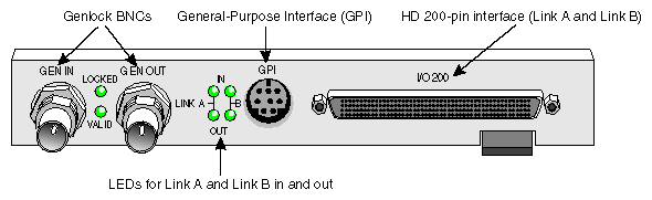
Figure B-1 shows the HD I/O front panel connectors.
The cables supplied with the HD I/O Board each have four 50-in connectors for attaching to equipment that complies with the SMPTE 274M standard. With the HD I/O Board, you can use these cables for 4:4:4:4 d ual-link mode or 4:2:2 s ingle-link mode. For 4:2:2 s ingle-link mode, ignore the alpha:
To set up the board for a digital video source, follow these steps:
Using the Panasonic-standard or Philips-standard cable included with the
HD I/O Board, attach the connector with the green label SGI <--- PANASONIC P1 or SGI <--- PHILIPS P1 to a device outputting data.Depending on the equipment to be connected to, use the Panasonic or Philips cable. If necessary, see “Cable Connectors” in Appendix A in Appendix A, “HD I/O Board Specifications” for an explanation of the labeling and color coding.
If you are using a device for alpha key data, also attach the connector with the red label SGI <--- PANASONIC P2 or SGI <--- PHILIPS P2 to a device outputting alpha.
-
/usr/sbin/vcp
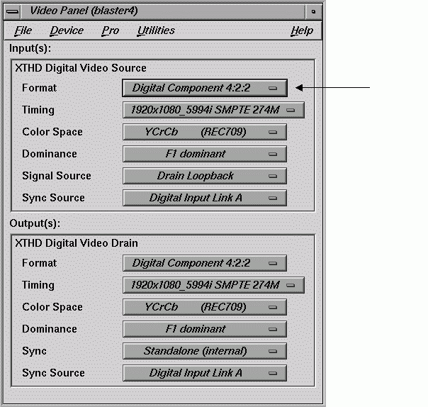
In the Inputs(s): HD I/O Digital Video Source section of the control panel vcp (pointed out in Figure B-3) for the channel(s) you are using, select the format that matches your equipment: Digital Component 4:2:2 (the default) or Digital Component 4:4:4:4.
In the Digital Video Source portion of the panel for the channel(s) you are using, select the timing that matches your equipment.

To set up the digital video output, follow these steps:
Using the Panasonic-standard or Philips-standard cable included with the HD I/O Board, attach the connector with the green label SGI ---> PANASONIC P3 or SGI ---> PHILIPS P3 to a device to which you want to send data.
If you use only one output, you must use this connector.
Depending on the equipment to be connected to, use the Panasonic or Philips cable. If necessary, see “Cable Connectors” in Appendix A in Appendix A, “HD I/O Board Specifications” for an explanation of the labeling and color coding.
If you are using a device for alpha key data, also attach the connector with the red label SGI ---> PANASONIC P4 or SGI ---> PHILIPS P4 to a device receiving alpha key data.
If necessary, call up the panel (/usr/sbin/vcp).
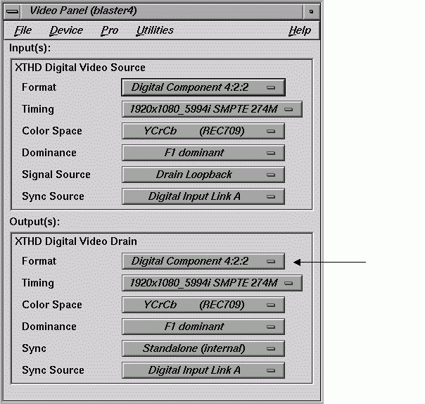
In the Output(s): Video Drain section of the control panel (pointed out in Figure B-4), select the format that matches your equipment: Digital Component 4:2:2 (the default) or Digital Component 4:4:4:4.
Select the timing that matches your equipment.
To set field dominance, in the “Input Timing” menu, select “F1 dominant” for the edit to occur on the nominal video field boundary, or “F2 dominant” for the edit to occur on the intervening field boundary.
For more information on field dominance, see “Field Dominance ” in Chapter 2 in Chapter 2, “Programming the HD I/O Board”.
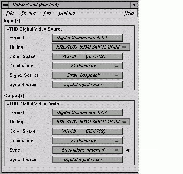
In the Output(s): Digital Video Drain section of the control panel, select the Sync format that matches your equipment:
stand-alone (not synced to another device): select Stand-alone (internal)
output sync to an external source connected to the genlock in: select Genlock
These two choices toggle; Figure B-5 shows the default.
To set up the HD I/O Board for an external sync source, follow these steps:
Select the appropriate external sync source in Output(s): Sync Source:
For a device connected to GEN IN, select External 1920x1080_5994_i or External 525 NTSC depending on your sync source.
If you are syncing to the device attached to SGI <--- PANASONIC/PHILIPS P1, select Digital Input Link A.
If you are syncing to the device attached to SGI <--- PANASONIC/PHILIPS P2, select Digital Input Link B.
If a genlock source has not yet been cabled to the HD I/O panel, any application in progress might generate an error message.
Connect the sync source equipment to one of the following connectors:
the GEN IN BNC on the I/O panel (see Figure B-1 if necessary)
or
the cable connector SGI <--- PANASONIC/PHILIPS P1 or SGI <--- PANASONIC/PHILIPS P2 (if this cable connector is not already attached to the device supplying sync)
If you are using the same signal for other equipment, attach a BNC cable to the GEN OUT BNC to loop the signal through the board.
Make sure the final element in the chain is terminated.
If the HD I/O Board is the last element in the sync chain, attach a terminator to the GEN OUT BNC.
-
If the yellow VALID LED is lit, an acceptable sync source is attached to the genlock input.
If the green LOCKED LED is lit, genlock is enabled (via vcp or an application), the reference is adequate, and the board is ready to use.
After you set the values in vcp to match your installation, save them; they are written to /usr/etc/video/videod.defaults. Select “Restore Settings” in the video control panel File menu to load the values in this file to vcp.
The last settings saved are automatically loaded every time the system is reinitialized. If the panel is running, current settings are in effect.
 | Note: You do not need to open the panel to activate its settings. |
You can also use File menu choices to restore the factory defaults and close the panel.