This chapter describes the panel plates for both SGI GSN products:
For the single-board product (XT-GSN-C-1XIO), see “Main SGI GSN Board Panel Plate”
For the two-board product (XT-GSN-C-2XIO), see “Main SGI GSN Board Panel Plate” and “XTOWN Board Panel Plate”
The panel plate on the main SGI GSN board has two ports (a GSN port and a XTOWN port) and six LEDs, as illustrated in Figure 1-1.
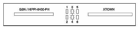
This section describes the port labeled GSN / HIPPI–6400–PH.
The GSN port connects the SGI GSN subsystem to the GSN fabric. The port can be attached to a switch, to another GSN endpoint, or to itself via a loopback device. The IRIX GSN subsystem (software and hardware together) cannot function unless this port is connected to a GSN node (which can be itself) with an appropriate cable or loopback device. For cable information, see “GSN (HIPPI-6400) Cables” in Chapter 2.
The GSN port's 100-position receptacle complies with the ANSI standard Information Technology - High-performance Parallel Interface - 6400 Mbit/s Physical Layer (HIPPI-6400-PH). This document can be viewed at this Web site: http://www.hippi.org/cDOCS.html .
The GSN port's receptacle is keyed (illustrated in Figure 1-2) to ensure correct mating with a GSN cable. The key consists of two slots/notches (one long/wide and one short/narrow) inside the receptacle that mate with two metal bars inside the cable connector.
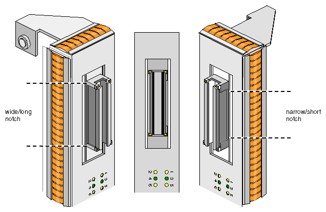
The XTOWN port is a 100-pin receptacle that complies with an SGI proprietary standard.
The XTOWN port connects the main SGI GSN board to an additional SGI GSN board called the XTOWN board. The link between these two boards provides an additional data path for supplying higher bandwidth to the GSN connection. The XTOWN port does not have to be connected for the SGI GSN subsystem to function. The cable for this link is described in “XTOWN Cable” in Chapter 2.
The behavior of the LEDs on the main SGI GSN board is controlled by firmware running on the board's HIPPI–6400-PH (SuMAC) component.
“LED Behavior During Normal Power On” describes the LEDs during normal power on.
“LED Behavior During Normal Operation” describes the LEDs during normal operation.
“Abnormal LED Behavior” describes the LED patterns that indicate problems.
Figure 1-3 illustrates normal LED patterns during power-on. Table 1-1 describes each LED during power-on.
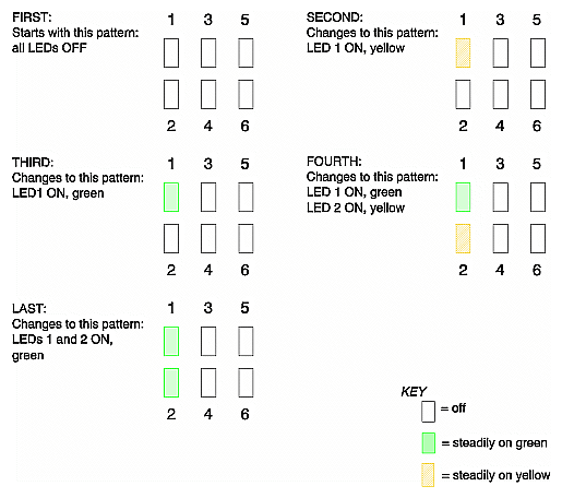
Table 1-1. Main SGI GSN Panel Plate LEDs During Power-on
LED | Color During Power-on | Description of Pattern |
|---|---|---|
1 | off or yellow | Power/Deskew LED |
|
| When OFF, indicates that the board is not powered on, that there is a problem with the physical link (that is, the cable), or that the GSN board has not yet transitioned out of reset. |
|
| When steadily yellow, indicates that the CLK2 signal on the physical link is detected by the local Destination (receiving) hardware. This is a normal pattern only during power-on or hardware reset, and should quickly transition to green. |
2 | off or yellow | CLK2/Credit_Ready LED |
|
| When OFF, indicates that the physical link has not yet been verified (as indicated by LED 1). |
|
| When steadily yellow, indicates that the HIPPI–6400-PH initialization and link reset protocol sequences have successfully completed and that the physical link is operational. This is a normal pattern only during power-on or reset, and should quickly transition to green. |
3 + 4 | off or green | Receive + Send LEDs |
|
| These LEDs have no meaning during power-on. |
5 + 6 | off or yellow | Lost Incoming/Outgoing Packet LEDs |
|
| These LEDs have no meaning during power-on. |
Figure 1-4 illustrates the normal LED pattern when operational firmware is running. Table 1-2 describes each LED during normal operation.
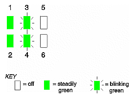
Table 1-2. Main SGI GSN Panel Plate LEDs During Normal Operation
LED | Color | Normal Pattern | Description of Pattern |
|---|---|---|---|
1 | green | steadily on green | Power/Deskew LED |
|
|
| When steadily green, indicates that the local Destination hardware's HIPPI–6400-PH signal skew compensation circuit is successfully deskewing the signals on this physical link. |
|
|
| In addition, green indicates that all the conditions required for the power-on yellow are true. |
|
|
| When blinking or when steadily yellow long after power-on, this indicates an error. See Table 3-1 . |
2 | green | steadily on green | CLK2/Credit_Ready LED |
|
|
| When steadily green, indicates that the link is not in a shutdown state and that the local Source hardware has at least one credit for at least one virtual channel with which to transmit data. |
|
|
| In addition, green indicates that all the conditions required for the power-on yellow are true. |
|
|
| When blinking or when steadily yellow long after power-on, this indicates an error. See Table 3-1 . |
3 | green | off or blinking | Receive LED |
|
|
| Each blink indicates reception of one HIPPI–6400 micropacket. |
4 | green | off or blinking | Send LED |
|
|
| Each blink indicates transmission of one HIPPI–6400 micropacket. |
5 | yellow | off | Lost Incoming Packet LED |
|
|
| When ON, this LED indicates an error. See Table 1-3 . |
6 | yellow | off | Lost Outgoing Packet LED |
|
|
| When ON, this LED indicates an error. See Table 1-3 . |
Table 1-3 describes the error LEDs on the main SGI GSN board's panel plate.
See “Troubleshooting With LEDs” in Chapter 3 for troubleshooting suggestions and for descriptions of abnormal combinations of LEDs.
Table 1-3. Error LEDs on Main SGI GSN Panel Plate
LED | Color | Normal Pattern | Description of Pattern |
|---|---|---|---|
5 | yellow | OFF | Lost Incoming Packet LED |
|
|
| An incoming micropacket has been lost. Each blink indicates that the local Destination hardware received an unexpected acknowledgment (that is, the received RSEQ value does not equal or fall between the last_valid+received_RSEQ and the local_Source's_last_TSEQ). The local endpoint has logged an RSEQ_Out_of_Range error. This pattern indicates a problem with the hardware at the remote endpoint or the cable between the endpoints. |
6 | yellow | OFF | Lost Outgoing Packet LED |
|
|
| An outgoing micropacket has been lost. Each blink indicates that the local Source hardware did not receive an acknowledgment (RSEQ) for one of its transmitted micropackets (TSEQ) within the worst-case round–trip timeout period. The local endpoint has retransmitted at least one micropacket and logged an RSEQ_Missing error. This pattern indicates a problem in the GSN fabric that is causing delays or loss: for example, a problem with the hardware at either the local or remote endpoint, or a problem with an intermediate switch or cable. |
The additional SGI GSN board has one XTOWN port and three LEDs, as illustrated in Figure 1-5. This board is known as the XTOWN board. It is a component of the two-board SGI GSN product.
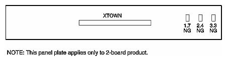
This port is identical to the port labeled XTOWN on the main board. See “XTOWN Port” for details.
