The OCTANE Channel Option (OCO) board allows you to transmit video output to multiple monitors from a single OCTANE system. Each monitor is assigned a different portion of the OCTANE frame buffer so that each monitor displays a unique image. You can use OCO to drive up to four monitors with RS170, VGA, or SVGA timing. Also, you can use the OCO board to produce timing formats not supported by OCTANE graphics alone. For example, while the standard field parallel formats, such as VGA, transmit data to a monitor on red, green, and blue wires, OCO can produce field-sequential formats that transmit all data on a single wire. These formats provide two channels of information needed to produce stereoscopic displays on many common head-mounted displays. Also, you can use OCO to “minify” a high resolution image, and produce a softened, lower resolution image.
Before continuing to configure the OCO, make sure that you also have installed the following:
the OCO board (see “Checking the OCTANE Channel Option Board Package Components” for installation information)
the breakout box (see “Connecting the Breakout Box Cable” for instructions)
the monitor(s) to the breakout box (see “Connecting the Monitors or Head-Mounted Display”)
You can install one OCO board for each OCTANE system. The OCO board can drive up to four independent channels from a single workstation.
This chapter describes how to configure the video formats that the OCO outputs. Specifically, this chapter covers the following topics:
If you have a dual-head system and want to move windows from one head to another, see the OCTANE Dual Head Installation Guide.
The OCO video output is easy to configure. Just specify the number of channels and the size of the video image. You can use the system command, setmon, to specify the output format (see “Using the setmon Command” for more information). If you are writing code for an application, use XSGIvc() to control the video output formats.
This section explains the following topics:
Figure 3-1 shows how the OCTANE Channel Option board is integrated into the graphics subsystem. The OCO subsystem interprets your video output specifications and converts the incoming digital information according to your specifications. Video comes in to the OCO subsystem where it is scaled and/or partitioned into the number and size of screens you have specified. Next, it goes to the framebuffer and then to the crossbar, which acts as a switch. Lastly, the crossbar routes the analog video signals to the appropriate monitors.
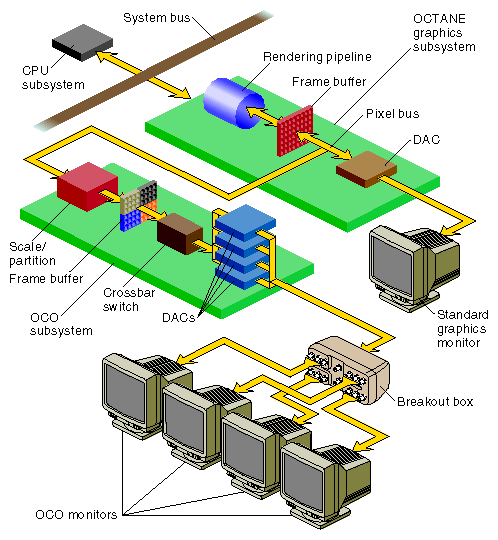
The number of screens into which the OCTANE Channel Option board divides the display surface is determined by several factors, including the OCO configuration that you specify and the graphics bandwidth of the OCTANE graphics system.
Table 3-1 lists the number of OCO channels, format resolution, and timing.
Table 3-1. OCO Video Output Channels, Format, and Timing
Number of Channels |
|
| External Sync |
|---|---|---|---|
4 | 640 x 486 Interlaced | RS-170 (NTSC RGB) |
|
4 | 640 x 480 Non-interlaced | VGA | Yes |
4a | 800 x 600 Non-interlaced | SVGA | Yes |
2 | 640 x 480 Non-interlaced | Field sequential |
|
1 | 640 x 480 Non-interlaced | VGA (filtered minify mode) | Yes |
2 | 800 x 486 Interlaced | RS-170 Field sequential |
|
2 | 800 x 486 Interlaced | RS-170 Field parallel component |
|
2a | 800 x 600 Non-interlaced | SVGA | Yes |
2[a] | 880 x 808 Interlaced | Field sequential |
|
2a | 1024 x 946 Interlaced | Field sequential |
|
2a | 1160 x 960 Interlaced | Field sequential |
|
[a] These modes are supported only on systems with OCTANE/MXI/SSI graphics. | |||
 | Note: VGA-to-NTSC converters produce composite NTSC. |
For information on external sync, see “Using OCO With External HSYNC or VSYNC Connectors”. For details on cable connections between the OCO board and OCO output monitors, see “Connecting the Monitors or Head-Mounted Display”. For information on the breakout box connection to a head-mounted device, see “Connecting the Head-Mounted Display”. For details on the breakout box connection for minify mode, see “Connecting to a Single Monitor: The Minify Mode”.
Video output format specifications are listed in Table 3-2.
Table 3-2. Video Output Format Specifications
Format Specification | Active Area |
|---|---|
4@640x486_30i | Four screens, each 640 x 486, at 30 Hz, interlaced RS-170 (NTSC RGB) |
4@640x480_60 | Four screens, each 640 x 480, at 60 Hz, non-interlaced (VGA) |
4@800x600_60a | Four screens, each 800 x 600, at 60 Hz, non-interlaced (SVGA) |
2@640x480_60q | Two screens, each 640 x 480, at 60 Hz, non-interlaced, field sequential |
1@640x480_60 | One screen, 1281 x 961 minified to 640 x 480, at 60 Hz, non-interlaced (VGA) |
2@800x486_30qi | Two screens, each 800 x 486, at 30 Hz, interlaced, field sequential |
2@800x486_30i | Two screens, each 800 x 486, at 30 Hz, interlaced, field parallel |
2@800x600_60a | Two screens, each 800 x 600, at 60 Hz, non-interlaced (SVGA) |
2@880x808_30qi[a] | Two screens, each 880 x 808, at 30 Hz, interlaced, field sequential |
2@1024x946_30qia | Two screens, each 1024 x 946, at 30 Hz, interlaced, field sequential |
2@1160x960_30qia | Two screens, each 1160 x 960, at 30 Hz, interlaced, field sequential |
[a] These modes are supported only on systems with OCTANE/MXI/SSI graphics. | |
| Note: OCO does not support an external genlock source. However, when OCO is in multi-screen mode, the outputs are synchronized with each other. |
Table 3-3 lists where you can find information about OCO cable connections.
Table 3-3. Information on OCO Cable Connections
Connection Type | See This Section |
|---|---|
Cable connections between the OCO board and the OCO output monitors | |
Breakout box connection to a head-mounted display | |
Breakout box connection for minify mode | |
HSYNC AND VSYNC connectors |
You can set the OCTANE Channel Option board's output video formats by using the setmon command, the same command you use to select the formats of OCTANE graphics.
This section covers the following topics:
For information on moving the cursor from screen to screen, see “Using the Four-Screen Mode”.
To configure and turn on the OCTANE Channel Option board, follow these steps:
If your Silicon Graphics system is powered off, follow the steps in the OCTANE Owner's Guide to plug in the system and power it on.
Log in to your account on the system.
Open a shell window, if necessary, by selecting “Unix Shell” from the Desktop Toolchest. Move the cursor inside the shell window.
Execute the setmon command and with the –S option. The format is
/usr/gfx/setmon -S formatThe option –S is required; note that it is uppercase. The format is the specification of the desired video output format. For example, suppose you want two screens at an 800 x 486 resolution; the format specification is 2@800x486_30i. So, to display this video format, enter
/usr/gfx/setmon -S 2@800x486_30iThis specification sets up OCO multichannel mode for two monitors, each at 800 x 486 pixels. The timing is 30 Hz and is interlaced (more than one vertical scan is used to reproduce a complete image).
To turn on OCO multichannel mode, see “Turning On the OCO”. Output formats are listed in “OCO Video Output Format Specifications”.
| Note: OCO does not support an external genlock source. However, when OCO is in multi-screen mode, the outputs are synchronized with each other. |
You can delay loading the video format by using the –x option to setmon. Note that you must be the superuser (su) to use the –x option. For example:
su
/usr/gfx/setmon -x -S 2@800x486_30i
|
The –x option saves the specified format to be used the next time the X server is started. This format does not take effect immediately; it is loaded the next time you restart graphics or reboot the system. For information on starting the X server and graphics mode, see “Turning On the OCO”.
For details on the setmon command and its options, see the setmon(3) reference page.
Loggging in remotely over the network or use a dumb terminal allows you to switch the OCO video modes without logging out and logging in again.
To switch to OCO multichannel mode when remotely logged in or on a dumb terminal, stop and restart the graphics subsystem:
/usr/gfx/setmon -x -S format ((/usr/gfx/stopgfx ; /usr/gfx/startgfx) >& /dev/null &) |
To switch to OCO multichannel mode when logged in on the graphics console, use setmon to select the format, and then log out and log in; you do not need to stop and restart the graphics.
| Note: It may be possible to switch to or from OCO multichannel mode without stopping and restarting the graphics subsystem if the new framebuffer screen size is less than or equal to the old screen size. |
If you wish, you can confirm that the OCO is active; for more information, refer to the section “Using gfxinfo to List Graphics Information”.
| Note: When the OCO is active, OCTANE graphics do not output to the standard OCTANE monitor (1280 x 1024). |
The HSYNC and VSYNC connectors provide external horizontal and vertical sync signals. These signals are locked to all active OCO outputs for a given mode, and can be used with monitors requiring separate sync inputs. Connect only one monitor to these outputs at a time. Use monitors that have sync-on-green as a built-in feature rather than monitors that require external inputs. If you must connect more than one monitor requiring external inputs to the HSYNC and VSYNC connectors, use a customer-supplied distribution amplifier. To use the HSYNC and VSYNC connectors, choose one of the following options:
Connect a single monitor to the HSYNC and VSYNC connectors on the breakout box.
Connect two or more monitors to a distribution amplifier that is connected to HSYNC and VSYNC connectors.
To enable the HSYNC and VSYNC connectors on the breakout box, you must use a video format combination that ends in _ext, for example, 4@460x480_60_ext. Table 3-1 lists the video formats that have external sync capabilities.
After a power-off, system reset, or reboot, the system remains in multichannel mode. To turn off OCO and return to standard graphics mode, when logged in remotely or on a dumb terminal, enter
/usr/gfx/setmon -x format ((/usr/gfx/stopgfx ; /usr/gfx/startgfx) >& /dev/null &) |
If you are logged in on the graphics console, run setmon, and then log out and log in.
The format is the output format of the screen when not in multichannel mode, for example, 1280x1024_60.
You can use the gfxinfo command to display information about the graphics subsystems installed in your system. Enter the following:
setenv DISPLAY :0 /usr/gfx/gfxinfo -v |
The first command sets up your environment so that the information is displayed on the screen from which you are typing the gfxinfo command. The –v option to gfxinfo specifies verbose output. An example of gfxinfo output for the format, 2@800x486_30i, looks like this:
Graphics board 0 is “IMPACTSR” graphics.
        Managed (“:0.0”) 800x972
        Product ID 0x3, 2 GEs, 2 REs, 4 TRAMs
        MGRAS revision 1, RA revision 0
        HQ rev B, GE11 rev B, RE4 rev C, PP1 rev A,
        VC3 rev A, CMAP rev E, Heart rev D
        19” monitor (id 0x1)
        OCO board present (rev 2)

        Channel 1:
         Origin = (0,0)
         Video Output: 800 pixels, 486 lines, 30.00Hz (2@800x486_30i)
        Channel 2:
         Origin = (0,486)
         Video Output: 800 pixels, 486 lines, 30.00Hz (2@800x486_30i)
|
The output tells you that the OCO board is installed and what its revision number is: OCO board present (rev 2). You also see statistics for each channel: the origin of each viewport (0,0 for Channel 1 and 0,486 for Channel 2) and the video output size, timing, and format (800 pixels, 486 lines, 30.00Hz (2@800x486_30i)).
The X display surface for OCTANE Channel Option board video formats is determined by the mode in which OCO is operating. The OCO places the origin of the first viewport starting at 0,0 in the upper left corner of the window.
This section provides examples of the screen origins for various output formats:
| Note: For more information on origins and display surface sizes, see “Using gfxinfo to List Graphics Information” and the gfxinfo(3G) reference page. Consult the gfxinfo output before using any formats. Silicon Graphics reserves the right to change origins as needed. |
For video output channels, formats, and timing information, see Table 3-1.
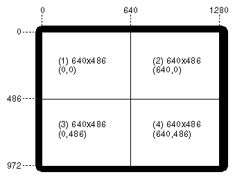
Figure 3-2 shows the maximum single display surface and origins for the viewports for the output format 4@640x486_30i. The actual display surface is the largest rectangular area that encloses the viewports. Its size is 1280 x 972 pixels.
This format divides the frame buffer into four independent channels. The size and location of each channel are shown in the figure. Each channel is 640 x 486 pixels and is output on the R, G, and B connectors on the breakout box. The timing for these signals is compatible with RS-170. If you require a composite signal, you must use an external encoder.
The output of gfxinfo -v for this format is
Graphics board 0 is “IMPACTSR” graphics.
        Managed (“:0.0”) 1280x972
        Product ID 0x3, 2 GEs, 2 REs, 4 TRAMs
        MGRAS revision 1, RA revision 0
        HQ rev B, GE11 rev B, RE4 rev C, PP1 rev A,
        VC3 rev A, CMAP rev E, Heart rev D
        19” monitor (id 0x1)
        OCO board present (rev 2)

        Channel 1:
         Origin = (0,0)
         Video Output: 640 pixels, 486 lines, 30.00Hz (4@640x486_30i)
        Channel 2:
         Origin = (640,0)
         Video Output: 640 pixels, 486 lines, 30.00Hz (4@640x486_30i)
        Channel 3:
         Origin = (0,486)
         Video Output: 640 pixels, 486 lines, 30.00Hz (4@640x486_30i)
        Channel 4:
         Origin = (640,486)
         Video Output: 640 pixels, 486 lines, 30.00Hz (4@640x486_30i)
|
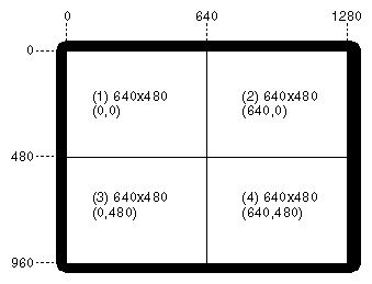
Figure 3-3 shows the maximum single display surface and origins for the viewports for the output format 4@640x480_60. The actual display surface is the largest rectangular area that encloses the viewports. Its size is 1280 x 960 pixels.
This format divides the frame buffer into four independent channels. The size and location of each channel are shown in the figure. Each channel is 640 x 480 pixels and is output on the R, G, and B connectors on the breakout box. This format is non-interlaced with a 60 Hz frame update rate. The timing for these signals is compatible with VGA resolution. Typically, this mode is used with sync-on-green. The monitors that are used with this format must be able to accept sync-on-green rather than external H and V sync. OCO can produce one channel of separate H and V sync, which is timed correctly for any of the OCO channels. See Table 3-1 for a listing of formats that you can use with H and V sync and “Using OCO With External HSYNC or VSYNC Connectors”.
The output of gfxinfo -v for this format is
Graphics board 0 is “IMPACTSR” graphics.
        Managed (“:0.0”) 1280x960
        Product ID 0x3, 2 GEs, 2 REs, 4 TRAMs
        MGRAS revision 1, RA revision 0
        HQ rev B, GE11 rev B, RE4 rev C, PP1 rev A,
        VC3 rev A, CMAP rev E, Heart rev D
        19” monitor (id 0x1)
        OCO board present (rev 2)

        Channel 1:
         Origin = (0,0)
         Video Output: 640 pixels, 480 lines, 60.00Hz (4@640x480_60)
        Channel 2:
         Origin = (640,0)
         Video Output: 640 pixels, 480 lines, 60.00Hz (4@640x480_60)
        Channel 3:
         Origin = (0,480)
         Video Output: 640 pixels, 480 lines, 60.00Hz (4@640x480_60)
        Channel 4:
         Origin = (640,480)
         Video Output: 640 pixels, 480 lines, 60.00Hz (4@640x480_60)
|
| Note: External sync is supported in this format; see “Using OCO With External HSYNC or VSYNC Connectors” for more information. |
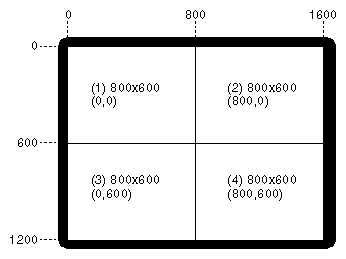
Figure 3-4 shows the maximum single display surface and origins for the viewports for the output format 4@800x600_60. The actual display surface is the largest rectangular area that encloses the viewports. Its size is 1600 x 1200 pixels.
This format divides the frame buffer into four independent channels. The size and location of each channel are shown in the figure. Each channel is 800 x 600 pixels and is output on the R, G, and B connectors on the breakout box. This non-interlaced format has a 60 Hz frame update rate. The timing for these signals is compatible with SVGA resolution. Typically, this mode is used with sync-on-green. The monitors that are used with this format must be able to accept sync-on-green rather than external H and V sync. OCO can produce one channel of separate H and V sync, which is timed correctly for any of the OCO channels.
The output of gfxinfo -v for this format is
Graphics board 0 is “IMPACTSR” graphics.
        Managed (“:0.0”) 1600x1200
        Product ID 0x3, 2 GEs, 2 REs, 4 TRAMs
        MGRAS revision 1, RA revision 0
        HQ rev B, GE11 rev B, RE4 rev C, PP1 rev A,
        VC3 rev A, CMAP rev E, Heart rev D
        19” monitor (id 0x1)
        OCO board present (rev 2)

        Channel 1:
         Origin = (0,0)
         Video Output: 800 pixels, 600 lines, 60.10Hz (4@800x600_60)
        Channel 2:
         Origin = (800,0)
         Video Output: 800 pixels, 600 lines, 60.10Hz (4@800x600_60)
        Channel 3:
         Origin = (0,600)
         Video Output: 800 pixels, 600 lines, 60.00Hz (4@800x600_60)
        Channel 4:
         Origin = (800,600)
         Video Output: 800 pixels, 600 lines, 60.00Hz (4@800x600_60)
|
| Note: External sync is supported in this format; see “Using OCO With External HSYNC or VSYNC Connectors” for more information. |
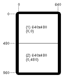
Figure 3-5 shows the maximum single display surface and origins for the viewports for the output format 2@640x480_60q. The actual display surface is the largest rectangular area that encloses the viewports. Its size is 640 x 960 pixels.
This format divides the frame buffer into two independent channels. The size and location of each channel are shown in the figure. Each channel is 640 x 480 pixels and is output on the R and G connectors for Channel 1 of the breakout box. This format is a non-interlaced, field-sequential format with a 60 Hz update rate.
The output of gfxinfo -v for this format is
Graphics board 0 is “IMPACTSR” graphics.
        Managed (“:0.0”) 640x960
        Product ID 0x3, 2 GEs, 2 REs, 4 TRAMs
        MGRAS revision 1, RA revision 0
        HQ rev B, GE11 rev B, RE4 rev C, PP1 rev A,
        VC3 rev A, CMAP rev E, Heart rev D
        19” monitor (id 0x1)
        OCO board present (rev 2)

        Channel 1:
         Origin = (0,0)
         Video Output: 640 pixels, 480 lines, 60.00Hz (2@640x480_60q)
        Channel 2:
         Origin = (0,480)
         Video Output: 640 pixels, 480 lines, 60.00Hz (2@640x480_60q)
|
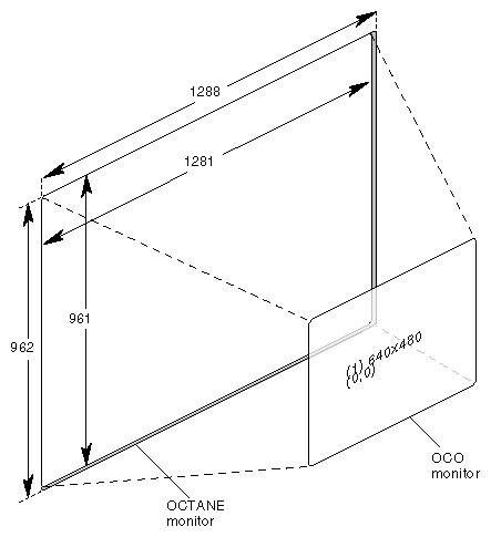
Minify mode produces a smooth image, without jagged or broken surfaces. This mode uses a rendering technique that takes a portion of a group of pixels and “minifies” them to produce a clear, smooth representation of the original image. For example, a video game developer can create a video game on an OCTANE system and output the game in OCO minify mode to see what it looks like on a typical VGA or TV screen.
Figure 3-6 shows the maximum single display surface (shaded area, 1288 x 962) and origins for the viewport (unshaded area, 1281 x 962) for the output format 1@640x480_60. The OCTANE viewport (1281 x 961) displays as 640 x 480 on the OCO monitor. Note that seven pixels at the end of each line and the bottom line on the screen are not displayed (as shown in the shaded area in Figure 3-6).
The output of gfxinfo -v for this format is
Graphics board 0 is “IMPACTSR” graphics.
        Managed (“:0.0”) 1288x962
        Product ID 0x3, 2 GEs, 2 REs, 4 TRAMs
        MGRAS revision 1, RA revision 0
        HQ rev B, GE11 rev B, RE4 rev C, PP1 rev A,
        VC3 rev A, CMAP rev E, Heart rev D
        19” monitor (id 0x1)
        OCO board present (rev 2)

        Channel 4:
         Origin = (0,0)
         Video Output: 640 pixels, 480 lines, 60.00Hz (1@640x480_60)
|
| Note: External sync is supported in this format; see “Using OCO With External HSYNC or VSYNC Connectors” for more information. |
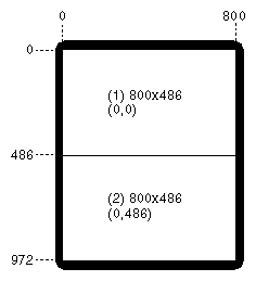
Figure 3-7 shows the maximum single display surface and origins for the viewports for the output format 2@800x486_30qi. The actual display surface is the largest rectangular area that encloses the viewports. Its size is 800 x 972 pixels.
This format divides the frame buffer into two independent channels. The size and location of each channel are shown in the figure. Each channel is 800 x 486 pixels and is output on the R and G connectors for Channel 1 of the breakout box. This format is an interlaced, field-sequential format with a 30 Hz update rate.
The output of gfxinfo -v for this format is
Graphics board 0 is “IMPACTSR” graphics.
        Managed (“:0.0”) 800x968
        Product ID 0x3, 2 GEs, 2 REs, 4 TRAMs
        MGRAS revision 1, RA revision 0
        HQ rev B, GE11 rev B, RE4 rev C, PP1 rev A,
        VC3 rev A, CMAP rev E, Heart rev D
        19” monitor (id 0x1)
        OCO board present (rev 2)

        Channel 1:
         Origin = (0,0)
         Video Output: 800 pixels, 484 lines, 30.00Hz (2@800x486_30qi)
        Channel 2:
         Origin = (0,484)
         Video Output: 800 pixels, 484 lines, 30.00Hz (2@800x486_30qi)
|
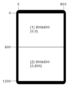
Figure 3-8 shows the maximum single display surface and origins for the viewports for the output format 2@800x600_60. The actual display surface is the largest rectangular area that encloses the viewports. Its size is 800 x 1200 pixels.
This format divides the frame buffer into two independent channels. The size and location of each channel are shown in the figure. Each channel is 800 x 600 pixels and is output on the R, G, and B connectors on the breakout box. This non-interlaced format has a 60 Hz frame update rate. The timing for these signals is compatible with SVGA resolution. Typically, this mode is used with sync-on-green. The monitors that are used with this format must be able to accept sync-on-green rather than external H and V sync.
The output of gfxinfo -v for this format is
Graphics board 0 is “IMPACTSR” graphics.
        Managed (“:0.0”) 800x1200
        Product ID 0x3, 2 GEs, 2 REs, 4 TRAMs
        MGRAS revision 1, RA revision 0
        HQ rev B, GE11 rev B, RE4 rev C, PP1 rev A,
        VC3 rev A, CMAP rev E, Heart rev D
        19” monitor (id 0x1)
        OCO board present (rev 2)

        Channel 1:
         Origin = (0,0)
         Video Output: 800 pixels, 600 lines, 60.10Hz (2@800x600_60)
        Channel 2:
         Origin = (0,600)
         Video Output: 800 pixels, 600 lines, 60.10Hz (2@800x600_60)
|
| Note: External sync is supported in this format; see “Using OCO With External HSYNC or VSYNC Connectors” for more information. |
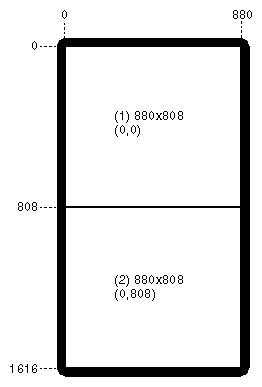
Figure 3-9 shows the maximum single display surface and origins for the viewports for the output format 2@880x808_30qi. The actual display surface is the largest rectangular area that encloses the viewports. Its size is 880 x 1616 pixels.
This format divides the frame buffer into two independent channels. The size and location of each channel are shown in the figure. Each channel is 880 x 808 pixels and is output on the R and G connectors for Channel 1 of the breakout box. This format is an interlaced, field-sequential format with a 30 Hz update rate.
The output of gfxinfo -v for this format is
Graphics board 0 is “IMPACTSR” graphics.
        Managed (“:0.0”) 880x1616
        Product ID 0x3, 2 GEs, 2 REs, 4 TRAMs
        MGRAS revision 1, RA revision 0
        HQ rev B, GE11 rev B, RE4 rev C, PP1 rev A,
        VC3 rev A, CMAP rev E, Heart rev D
        19” monitor (id 0x1)
        OCO board present (rev 2)

        Channel 1:
         Origin = (0,0)
         Video Output: 880 pixels, 808 lines, 30.00Hz (2@880x808_30qi)
        Channel 2:
         Origin = (0,808)
         Video Output: 880 pixels, 808 lines, 30.00Hz (2@880x808_30qi)
|
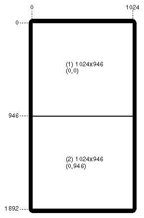
Figure 3-10 shows the maximum single display surface and origins for the viewports for the output format 2@1024x946_30qi. The actual display surface is the largest rectangular area that encloses the viewports. Its size is 1024 x 1892 pixels.
This format divides the frame buffer into two independent channels. The size and location of each channel are shown in the figure. Each channel is 1024 x 946 pixels and is output on the R and G connectors for Channel 1 of the breakout box. This format is an interlaced, field-sequential format with a 30 Hz update rate.
The output of gfxinfo -v for this format is
Graphics board 0 is “IMPACTSR” graphics.
      Managed (“:0.0”) 1024x1892
      Product ID 0x3, 2 GEs, 2 REs, 4 TRAMs
      MGRAS revision 1, RA revision 0
      HQ rev B, GE11 rev B, RE4 rev C, PP1 rev A,
      VC3 rev A, CMAP rev E, Heart rev D
      19” monitor (id 0x1)
      OCO board present (rev 2)

      Channel 1:
       Origin = (0,0)
       Video Output: 1024 pixels, 946 lines, 30.00Hz (2@1024x946_30qi)
      Channel 2:
       Origin = (0,946)
       Video Output: 1024 pixels, 946 lines, 30.00Hz (2@1024x946_30qi)
|
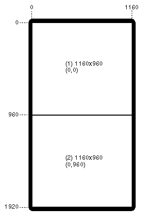
Figure 3-11 shows the maximum single display surface and origins for the viewports for the output format 2@1160x960_30qi. The actual display surface is the largest rectangular area that encloses the viewports. Its size is 1160 x 1920 pixels.
This format divides the frame buffer into two independent channels. The size and location of each channel are shown in the figure. Each channel is 1160 x 960 pixels and is output on the R and G connectors for Channel 1 of the breakout box. This format is an interlaced, field-sequential format with a 30 Hz update rate.
The output of gfxinfo -v for this format is
Graphics board 0 is “IMPACTSR” graphics.
      Managed (“:0.0”) 1160x1920
      Product ID 0x3, 2 GEs, 2 REs, 4 TRAMs
      MGRAS revision 1, RA revision 0
      HQ rev B, GE11 rev B, RE4 rev C, PP1 rev A,
      VC3 rev A, CMAP rev E, Heart rev D
      19” monitor (id 0x1)
      OCO board present (rev 2)

      Channel 1:
       Origin = (0,0)
       Video Output: 1160 pixels, 960 lines, 30.00Hz (2@1160x960_30qi)
      Channel 2:
       Origin = (0,960)
       Video Output: 1160 pixels, 960 lines, 30.00Hz (2@1160x960_30qi)
|