This chapter covers installing and removing the OCTANE Channel Option (OCO) board in your OCTANE workstation.
The following topics are covered in this chapter:
Before shutting down your system and installing the OCO board, be sure you have the current version of the IRIX™ operating system installed on your system. Install the operating system that came with your OCO board before installing the hardware.
Read the flier on software that comes with this package. Also read any release notes and the notes in the CD booklet for detailed information about the software. To review release notes, choose Toolchest > Help > Release Notes. Release notes are available here after the software has been installed.
To display ASCII text in an IRIX shell, at the prompt, type cdrelnotes.
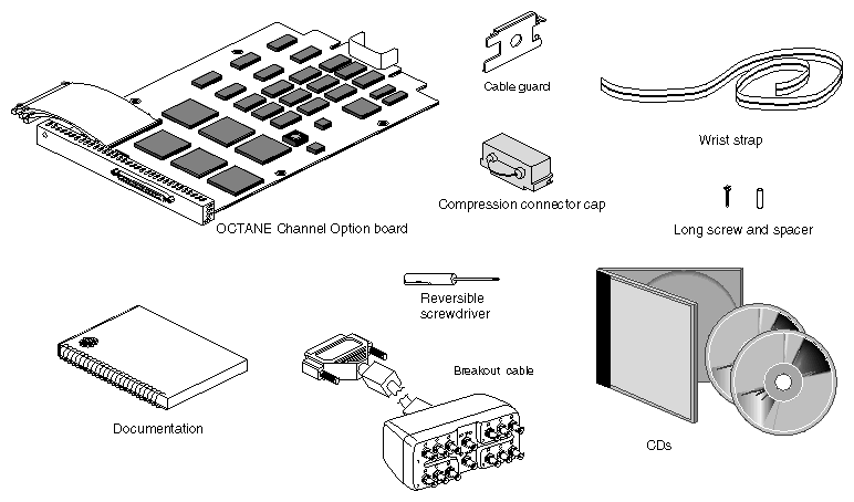
It's a good idea to check your shipment when you receive it. You should receive the supplies shown in Figure 1-1.
This section contains instructions on installing the OCTANE Channel Option board.
Installing an OCTANE Channel Option board requires following a series of steps that lead up to the board installation, through the steps that complete the task. These detailed steps begin on the following page.
A wrist strap.
Documentation.
A reversible screwdriver.
A cable guard.
A spacer and long screw.
The OCTANE Channel Option board with three flex cables attached.
The breakout box cable.
An XIO compression connector cap to protect the graphics board XIO compression connector when it is out of the workstation. (An extra cap comes with this shipment. Caps came with the OCTANE workstation.)
A blank panel, if you are removing the OCTANE Channel Option board and are not replacing it. (A blank panel came with the workstation and was in the slot filled by the OCTANE Channel Option board.)
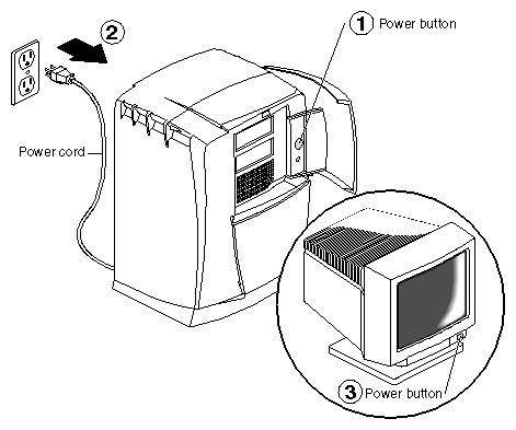
Open the cover and push the power button to power off the OCTANE workstation.
Unplug the power cord.
Push the power button on the monitor to power it off. Wait five minutes.
Face the rear of the workstation.

Warning: The heat sinks on the XIO boards become very hot. Wait 5 minutes after powering off the OCTANE workstation before you remove the XIO module. Test before touching any of the XIO boards.
Remove the monitor cable or other cables from the XIO module. (For illustration purposes, only the monitor cable is shown in Figure 1-3.)
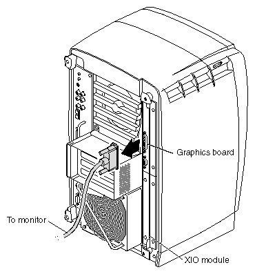
The XIO module can be thought of as a tray to which the XIO graphics boards and option boards are attached.
 | Note: The XIO module is always installed with the graphics board toward the top of the workstation, in the upper left quadrant. See Figure 1-3. |
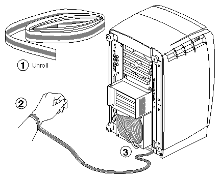
 | Caution: The components inside the OCTANE workstation are extremely sensitive to static electricity; you must wear the wrist strap while replacing parts inside the workstation. |
To attach the wrist strap, follow these steps:
Unwrap the first two folds of the band and wrap the exposed adhesive side firmly around your wrist.
Unroll the rest of the band and peel the liner from the copper foil at the opposite end.
Attach the copper foil to a convenient and exposed electrical ground, such as a metal part of the OCTANE workstation.
Before removing the XIO module, you must power off the OCTANE workstation, wait
five minutes after powering off the workstation to allow the heat sinks to cool, and attach the wrist strap. If you have not already done this, go to “Preparing the Workstation” and follow the instructions through attaching the wrist strap. Then return here and follow the directions on the next page.
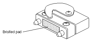
When you remove the XIO module, the compression connectors on the back of the XIO module (XIO boards) are accessible and easily damaged. All XIO graphics boards have compression connectors, and most XIO option boards do. The OCTANE Channel Option board does not.
| Caution: The compression connectors on each XIO board are very delicate and easily damaged. Do not touch or bump the gold, bristled pad. For more information on care and cleaning of compression connectors, see the OCTANE Workstation Owner's Guide. |
| Warning: The heat sinks on the XIO boards become very hot. Wait 5 minutes after powering off the OCTANE workstation before you remove the XIO module. Test before touching any of the XIO boards. |
The XIO module is the holding mechanism for XIO graphics or XIO option boards and holds up to four boards. It can be thought of as a tray to which boards are attached.
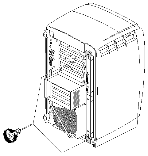
Loosen the two captive screws in the XIO module handles until the handles move free from the workstation.
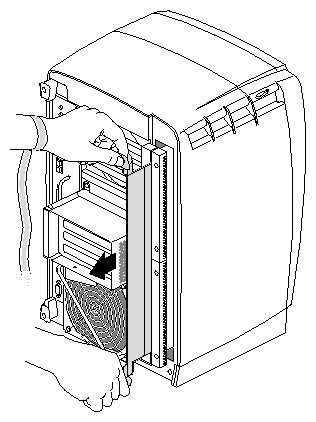
Grasp the handles and pull until the XIO module protrudes a few inches from the chassis.
The handles and the XIO module move out about two inches before the I/O panels move.
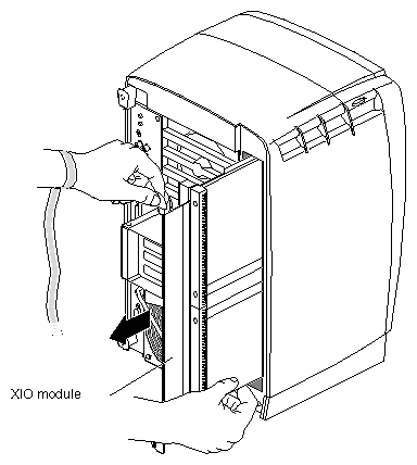
Continue to pull on the handles until the XIO module releases from the workstation.
Grasp the XIO module along its length, and support the module and XIO boards with your hands as you remove them from the chassis.
The handles protrude from beneath the XIO boards when the XIO module is out of the chassis. When protruding, the identification slots for the XIO boards (D and A, B and C) are visible. Slots B and C are on the opposite side of the XIO module from slots D and A.
Note: Do not push on the handle area after you have removed the XIO module. The XIO module locks to the workstation only if the handle area is protruding. Place the XIO module on a flat, antistatic surface. An empty antistatic bag on your desk works well.
Note: Figure 1-9 above shows an OCTANE/SI graphics board in slot A and a blank panel in slot D. OCTANE/SSI or /MXI graphics are twice the width of the OCTANE/SI board and reside in slots D and A. See Appendix A for illustrations of different graphics boards and the OCTANE Channel Option board.
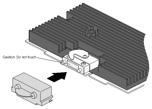
Place a cap on the XIO graphics board compression connector.
Note: The cap prevents damage to the gold (front) surface when the XIO boards are removed from OCTANE. These caps are placed on any XIO compression connector as soon as the XIO module is removed from the chassis, and then removed before placing the XIO module back in the chassis.
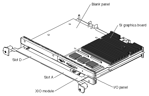
The XIO module is the holding mechanism for XIO graphics or XIO option boards and holds up to four boards. It can be thought of as a tray to which boards are attached. The four quadrants of the XIO module are slots A, B, C, and D. Slots D and A are on one side, Slots B and C on the other. A graphics board, option board, or blank panel attaches to each slot on the XIO module.
The XIO module must be placed so that the graphics board in slot A is in the upper left corner, or the graphics board may overheat and be damaged.
The graphics board is always in slot A or slot A and (covering) slot D.
Option boards occupy slots B and C and possibly D.
The OCTANE Channel Option board only installs in slot B.
Graphics and option boards may be linked by flex cables.
A baffle must be attached to two side-by-side blank panels to ensure proper air flow.
The XIO compression connector is always covered by a protective cap when an XIO board is out of the OCTANE workstation.
Extra caps for the compression connectors are shipped with the workstation.
Attaching the OCTANE Channel Option board is a lengthy process. Here is a quick overview of the preliminary steps.
Before installing the OCTANE Channel Option board, you must follow a series of steps detailed in the preceding sections of this chapter, beginning on page 1. If you have not already done so, go to page 1 and follow the instructions through removing the XIO module. If you have already removed the XIO module, go to step 1 on the next page. (Be sure you also read “About the XIO Module and XIO Boards” before beginning your task.)
| Caution: Do not touch the gold (front) surface of the XIO compression connector. Touching it could damage the connector. Place a protective cap on the XIO compression connector, to prevent damage when the XIO boards are removed from the OCTANE workstation. |
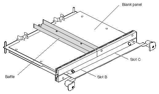
Turn the XIO module so that slots B and C are facing you. Select your next step from Table 1-1.
Table 1-1. Choosing the Next Instruction
If You Have
Go to
An option board in slot B
The option board installation guide for instructions on removing the board
A blank panel in slot B and an option board in slot C
Step 3
Blank panels in slots B and C
Step 2
Remove the baffle attached to the two blank panels:
Using a Phillips screwdriver, remove the four screws holding the baffle to the two blank panels.
Remove the baffle.
Replace the two screws into the blank panel in slot C.
Remove the blank panel. Keep it in case you remove an option board. A blank panel or board must be in place in each slot on the XIO module.
Keep the baffle. The baffle must be in place over two blank panels to ensure proper air flow, if you ever replace the blank panels at a later date.
Note: The baffle is never used with an option board, only with two side-by-side blank panels.
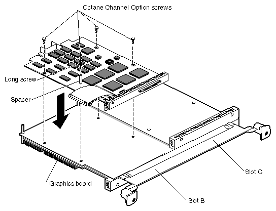
Place the OCTANE Channel Option board in slot B on the XIO module, aligning the holes in the board to the standoffs on the XIO module.
Note: The OCTANE Channel Option board can only be installed in slot B because it must attach to the graphics board in slot A. Insert and tighten the four screws through the OCO board and into the standoffs on the XIO module.
Insert the long screw into spacer, through the hole on the OCO board, and into the standoff on the XIO module.
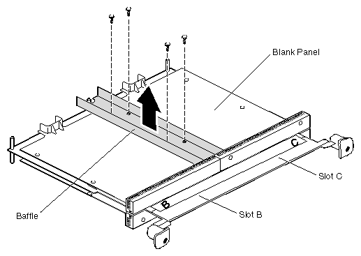
| Caution: Do not install the baffle. The baffle is used only with two side-by-side blank panels. |
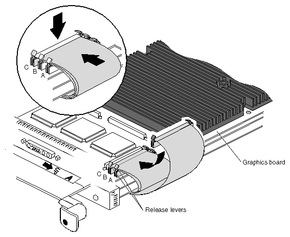
Turn over the XIO module so that you are facing the graphics board in slot A or A and D.
Attach the flex cables from the OCTANE Channel Option board in slot B to the graphics board in slot A.
Attach the connector with the shortest flex cable (from the OCTANE Channel Option board) to connector A on the graphics board. Press down on the middle of the connector to ensure proper seating.
Lay the middle flex cable through the release levers of connector A, then attach the connector. Press down on the middle of the connector to seat it.
Lay the longest flex cable through the release levers of connectors A and B. Attach the connector and press down on the middle of the connector to seat it.
This section describes how to install the cable guard on the OCTANE Channel Option board.
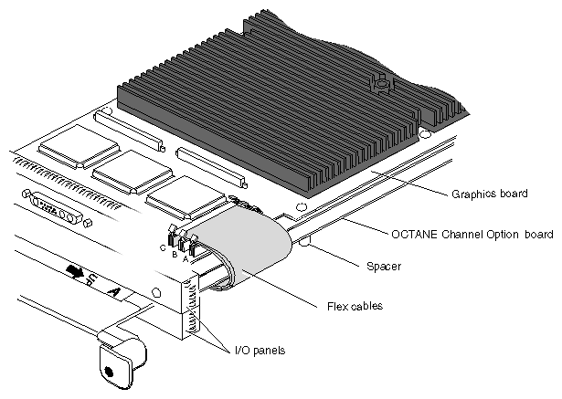
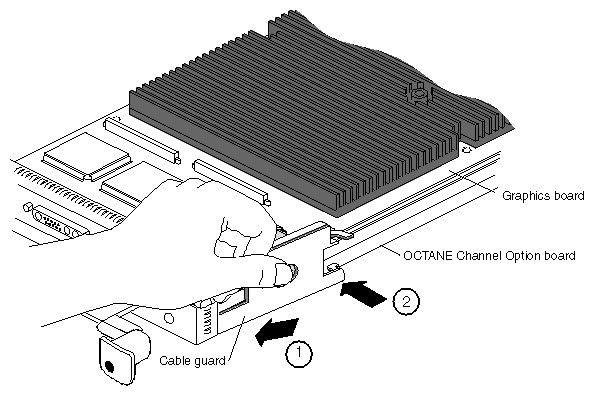
The flex cable guard protects the flex cables from being scratched or caught on the chassis when the XIO module is inserted or removed from the workstation.
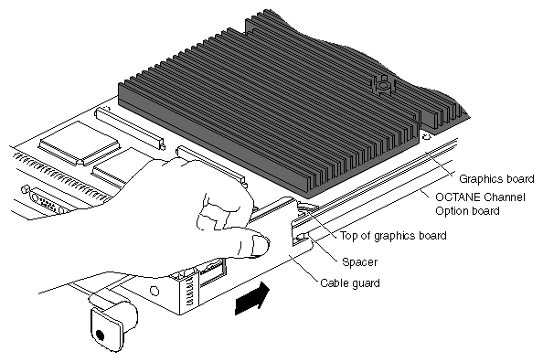
The flex cable guard slides under the I/O panels and attaches beneath the screw on the graphics board, and behind the spacer on the OCO board.
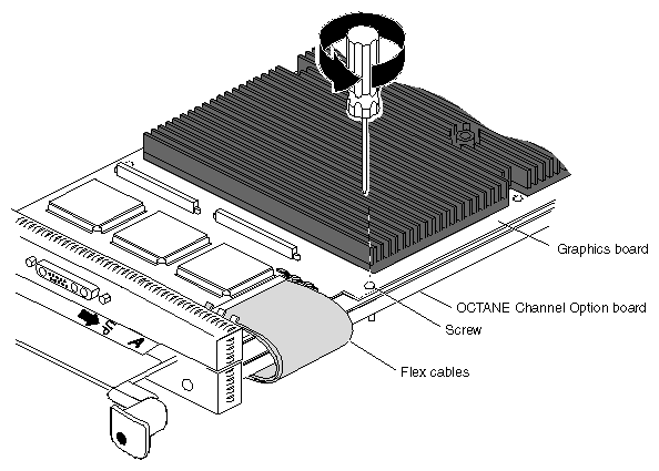
Remove the screw from the graphics board as shown in Figure 1-17.
Slide the two prongs under the I/O panels.
Push the cable protector toward the flex cables, laying the top hook on the top of the graphics board. Continue placing pressure on the flex cables.
Press down on the center hole of the cable guard and slide it toward the back of the XIO module until its half-hook rests behind the spacer on the OCO board.
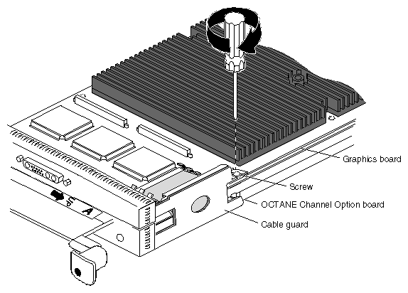
Place the screw from the graphics board through the hook on the cable guard and the graphics board, and into the standoff on the XIO module.
Note: If you receive a screw with the cable guard, use this longer screw instead of the screw you just removed from the graphics board. You have finished installing the flex cables and cable guard.
Remove the cap from the XIO compression connector on the graphics board. Keep the cap to protect the compression connector should you ever remove this board.
Go to page 24 for instructions on replacing the XIO module.
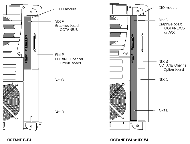
| Caution: The XIO module must be replaced with the graphics board toward the interior of the workstation to prevent overheating and damage to the boards. If the XIO module with the OCTANE/SSI or OCTANE/MXI graphics board is inserted incorrectly, a notifier appears during power on telling you to insert the XIO module with the graphics boards toward the interior of the workstation, and power-on stops. Power off the system and correctly insert the XIO module as shown in Figure 1-21. |
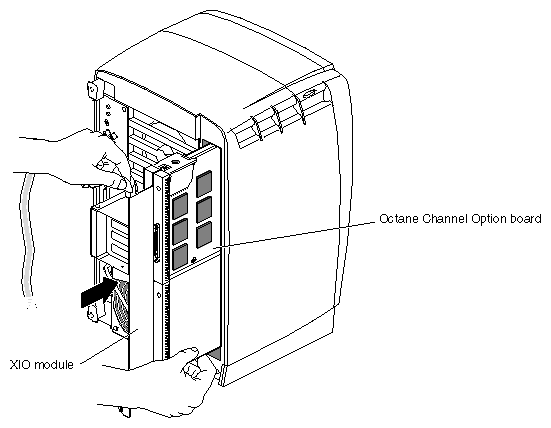
Follow these steps to install the XIO module:
Replace the XIO module in the OCTANE workstation. Slide the XIO module into guides on the top and bottom of the workstation.
Before you insert the XIO module, make sure the handle portion protrudes in a locked position from the I/O panels, as shown in Figure 1-22.
If the handles are flush with the I/O panels, the XIO module will stop during insertion. Pull out the handles until the sliding portion of the XIO module looks like that shown in Figure 1-22, and then continue inserting the XIO module into the chassis.
Use the handles to push the XIO module into a locked position.
Note: The I/O panels are not completely flush with each other or the chassis; there is some slight variation in the depth of the individual boards.
Tighten the screws in the handles so that the XIO module is attached to the chassis.
Remove the wrist strap.
Attach any other option board cables.
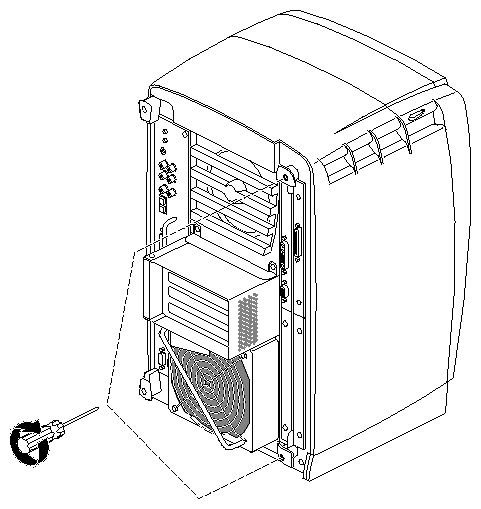
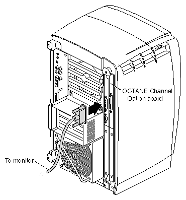
You have finished replacing the XIO module and are ready for the next step. Go to “Powering On the OCTANE Workstation”.
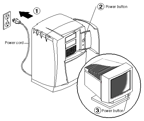
Plug the power cord into an electrical outlet.
Push the power button on the front of the OCTANE workstation.
Push the power button on your monitor.
Go to the next section for instructions on placing any upgrade label, and then go to Chapter 2, “Connecting to the Breakout Box.”
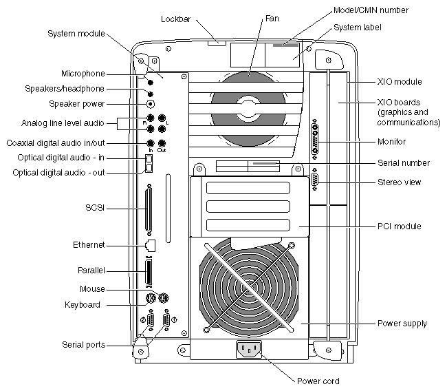
If you received a system upgrade label, place it on the system label (top of workstation).
Face the back of the OCTANE workstation. The system label (containing the model and CMN number) is located at the top center of the back of the workstation.
Place the label over the VCCI and CISPR 22 information.
Silicon Graphics, Inc. provides a comprehensive range of product support for its products. If you are in North America and would like support for your Silicon Graphics supported products, contact the Technical Assistance Center at 1-800-800-4SGI or your authorized service provider. If you are outside North America, contact the Silicon Graphics subsidiary or authorized distributor in your country.