This chapter describes how to set up a one or two module Origin200 system. It includes information about:
choosing a proper location for the server (tower configuration)
putting together the pieces of the system
attaching an Ethernet networking cable
attaching a serial (ASCII) terminal or other system console
attaching a second Origin200 module
attaching an optional Origin Vault expansion chassis
turning on the system
logging in for the first time
Specific information about mounting an Origin200 module in an equipment rack is provided in Chapter 3, “Installing an Origin200 System in a Rack.”
When choosing a location for your Origin200 server, follow these guidelines:
Proper electrical grounding is critical. With a two-module system, both modules must be on the same, grounded power supply. Otherwise, the Origin200 system board will be damaged. Modules may be connected to different electrical circuits, but those circuits must originate at the same power supply (electrical service entrance or breaker box).
For a tower (free-standing) system, make sure the surface on which you place the server is capable of supporting at least 40 pounds (18 kg) per module. Be aware that a fully-configured Origin200 module can weigh up to 75 pounds (34 kg) per module.
Be sure to provide adequate space for proper airflow and cooling. Refer to Table 1-4 in Chapter 1, “Overview of the Origin200 System” for a complete list of environmental specifications. Figure 2-1 below shows the minimum distances required around the chassis.
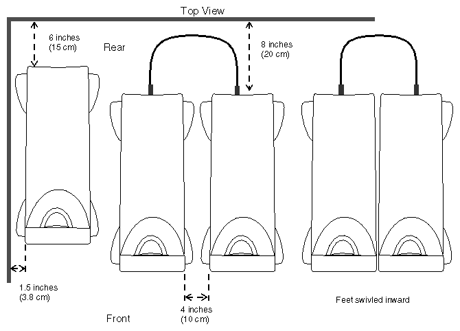
Figure 2-2 shows the various items that are packed with a basic Origin200 server in a tower configuration. (Low-profile blanking plates are packed inside the peripheral carrier). Your shipment may include additional options.
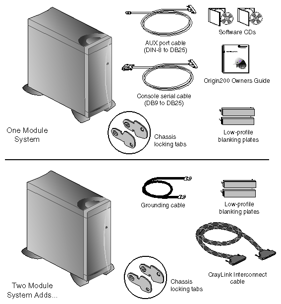
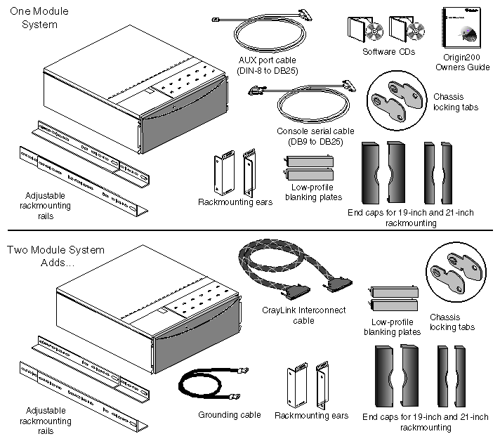
Figure 2-3 shows the various items shipped with an Origin200 server in a rack-mountable configuration. (Low-profile blanking plates are packed inside the peripheral carrier).
When you assemble as Origin200 server you attach various cables (system console, power, Ethernet network, ground, and CrayLink Interconnect) to the rear of the system. Figure 2-4 provides an overview of the various connectors that are available.
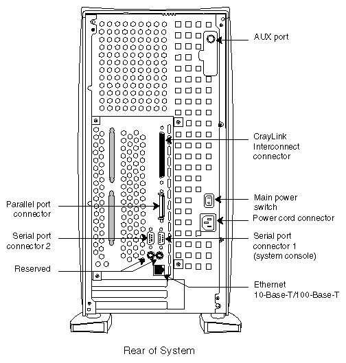
For a complete description of these connectors, see Chapter 1, “Overview of the Origin200 System.”
When working on a Origin200 server, follow these safety precautions:
Place the chassis on a surface capable of supporting a minimum of 40 lbs (about
18 kg) per module. A fully-configured Origin200 module can weigh up to 75 lbs (34 kg).Before opening the chassis, turn off the master power switch at the rear of the system. This disconnects power to the power supply. The software-power switch at the front of the chassis shuts off the server, but does not disconnect the power supply.
When opening the chassis, for example to install and remove additional peripherals and memory, always observe proper electrostatic discharge (ESD) procedures. Make sure you are properly grounded with a wrist or heel strap before handling sensitive boards and drives. All Silicon Graphics peripheral, memory, and upgrade options are shipped with wrist straps.
Follow these steps to assemble the Origin200 module.
Unpack each module that was shipped as part of your complete Origin200 system.
Make sure you have all the parts. See Figure 2-2 and Figure 2-3.
If you have additional memory or PCI option boards that you wish to install in the modules, do so now.
For instructions on removing the system cover, see “Removing the System Cover and Chassis Access Door” in Chapter 4.
For instructions on installing memory, see Chapter 5, “Installing and Removing Memory.”
For instructions on installing PCI option boards, see Chapter 6, “Installing and Removing PCI Option Boards.”
Do not install disk drives yet. These make the modules heavier and more difficult to move as you continue to set up the system.
If you are installing the Origin200 modules in an equipment rack, turn now to Chapter 3, “Installing an Origin200 System in a Rack.”
Follow the instructions for installing the Origin200 module in an equipment rack.
When you are finished installing the module in the equipment rack, return to the next section, “Attaching an Ethernet Networking Cable.”
If you are installing a tower (free-standing) Origin200 server, place it in the location you determined earlier (see “Choosing a Location For the Server.”)
After you have placed the server in the desired location (either in a free-standing, tower configuration, or mounted in an equipment rack), install any option drives.
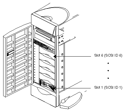
All 3.5 inch drives shipped from Silicon Graphics for use in Origin200 systems are attached to mounting sleds. The SCSI ID of the drive is set automatically when it is installed in the system. The bottom 3.5-inch drive slot (right-most slot in a rack system) is drive ID 1, and the top 3.5-inch drive slot (left-most slot in a rack system) is drive ID 6. See Figure 2-5.
Install any 3.5-inch drives as shown in Figure 2-6.
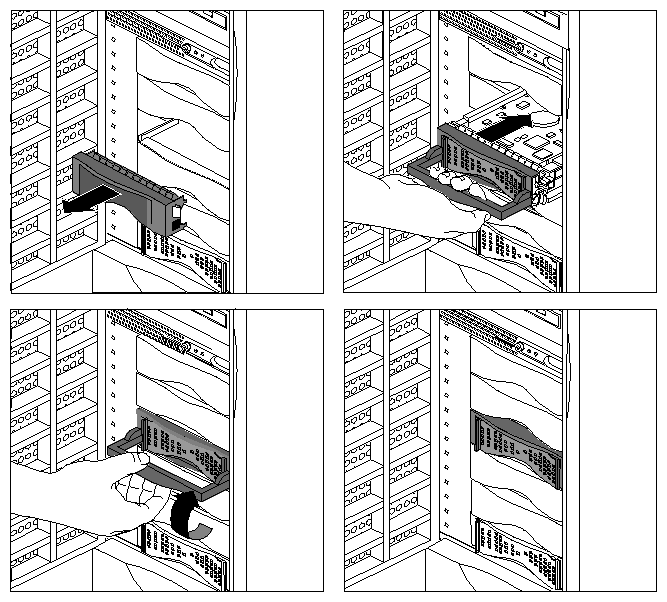
Save any blanking plates you remove in case you remove the drives later. For more information about using 3.5-inch drives, see Chapter 7, “Installing and Configuring Peripherals.”
 | Note: If you are installing a non-Silicon Graphics 5.25-inch drive, see “Configuring a 5.25-Inch Peripheral” in Chapter 7. |
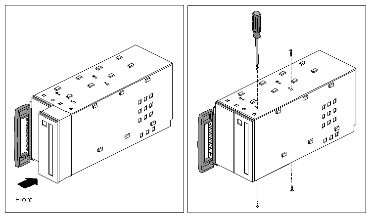
5.25-inch drives are installed in a removable carrier. Follow these step to remove the carrier:
See Figure 2-7.
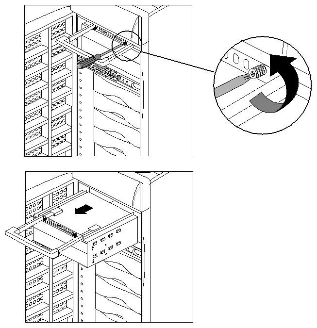
Install the 5.25-inch drive in the carrier. The carrier can hold one full-height drive or two half-height drives. Follow these steps to install the drive in the carrier:
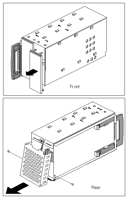
Remove one or two of the blanking plates from the front of the carrier, depending upon whether you are installing a half-height or a full-height drive.
Using a #2 Phillips screwdriver, remove the screws that hold the access plate to the rear of the carrier, then remove the access plate. See Figure 2-8.
Slide the drive into the peripheral carrier and attach it with four screws through the side of the carrier, as shown in Figure 2-9.
If the drive you are installing is a 1-inch high peripheral, there will be a gap in the front of the carrier not covered by the face of the drive. Cover this gap with one of the low-profile plates shipped with the server.
When installing the drive, be careful to keep track of its orientation in the carrier so that you do not install the drive upside down.
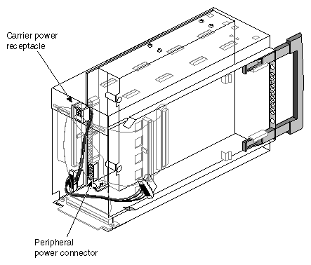
Attach one of the power connectors at the rear of the carrier to the drive. Use whichever connector fits conveniently for the position of the drive's power receptacle. See Figure 2-10.
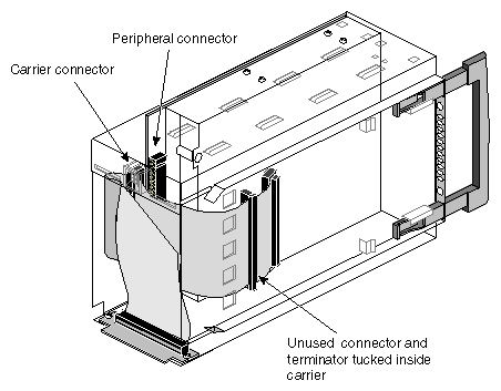
Attach one of the connectors on the SCSI cable to the drive. Use whichever connector fits conveniently for the position of the drive's SCSI connector. See Figure 2-11.
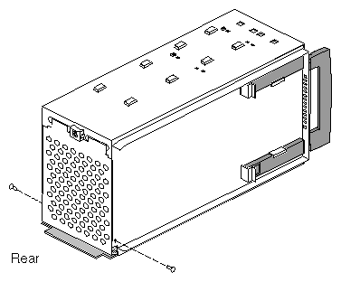
Replace the access plate. See Figure 2-12.
The plate should cover all of the loose wires (power and SCSI) at the rear of the carrier.
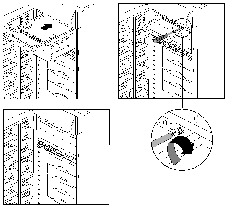
Note: Be sure to reinstall the access plate on the rear of the carrier. The plate protects the power and SCSI cables from damage when you slide the carrier into the system. Slide the carrier into the system, secure it with the captive screws, and push in the retractable handle. See Figure 2-13.
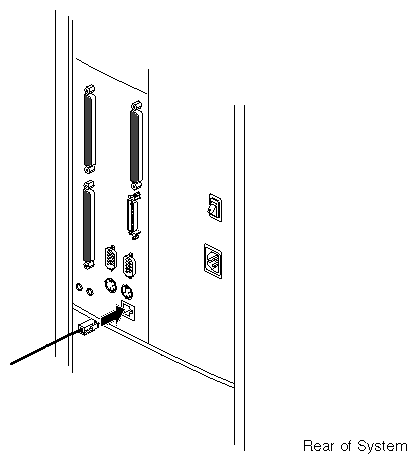
Connect the RS-232 serial cable (provided) to an ASCII terminal. The cable is approximately 10 feet (3 meters) long. Plug the D-shaped, 9-pin connector into serial port 1 on the back of the system, as shown in Figure 2-15.
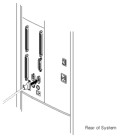
Connect the other end of the serial cable, which has a D-shaped, 25-pin connector, to a serial (ASCII) terminal.
You can use a computer, such as an IBM®-compatible or Macintosh®, or a workstation, such as a Silicon Graphics O2™ or Indy™, as the system console instead of an ASCII terminal. For more information, see “Using Another Computer or Workstation as the System Console” in Chapter 4.
When you connect two Origin200 modules together using a CrayLink Interconnect cable, one module becomes the master and the other becomes the slave. This relationship is set by a DIP switch located on the module system controllers (MSC) of the each machine, and has the following features:
Only the master module can have a system console.
The master module controls the power-on and power-off sequence.
You can communicate with the module system controller (through the AUX port) in the master, but not the slave module.
Both master and slave modules must have memory (DIMMs) installed in them.
The slave module does not require any disk drives.
When connecting power to the two modules, you may use different electrical circuits (circuits protected by individual fuses or breakers). However, both circuits must be connected to the same grounded power source (service entrance or breaker box).
 | Warning: If the chassis are not connected to the same, grounded power supply, resulting differences in ground potential (current) can damage components on the Origin200 main system board. |
Follow these steps to connect two Origin200 modules:
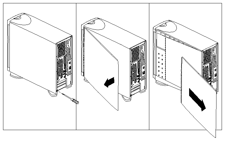
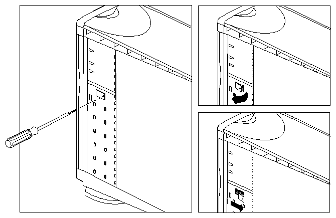
If the slave system is in a tower configuration, remove the side panel as shown in Figure 2-16.
Remove the module system controller (MSC) access plate, as shown in Figure 2-17
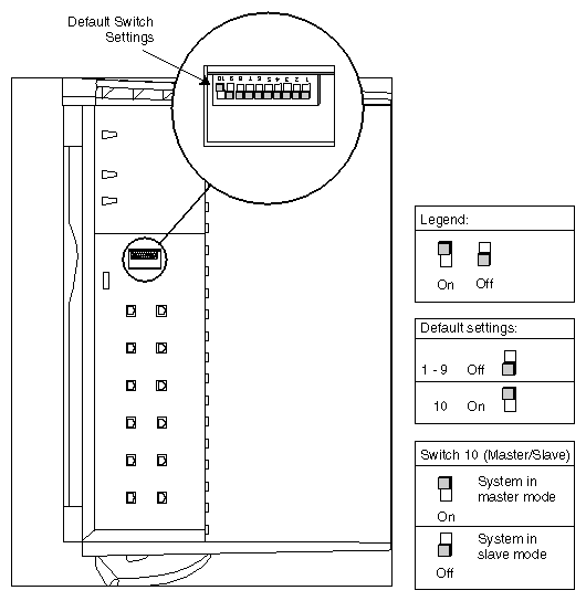
Locate the MSC DIP switch, as shown in Figure 2-18.
Using a ballpoint pen or similar, change switch 10 to “off” to place this module in slave mode. See Figure 2-18.
Replace the MSC access plate and, if this is a tower system, replace the side panel.
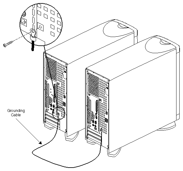
Connect the grounding cable between the two chassis, as shown in Figure 2-19. Do this first, before you connect the CrayLink Interconnect cable.
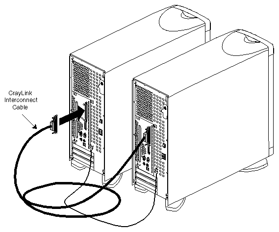
Connect the two modules with the CrayLink Interconnect cable, as shown in Figure 2-20. Be sure to tighten the thumbscrews on the connectors for proper Craylink operation.
-
Warning: You must connect the power cables to the same, grounded power supply or the system will be damaged.
You are finished connecting the modules. You can now turn on the system.
Follow these steps to turn on the system:
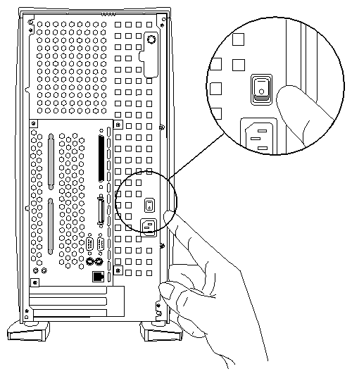
At the rear of the system, turn the master power switch on, as shown in Figure 2-21.
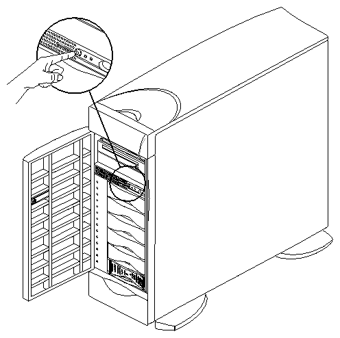
At the front of the system, press the power button, as shown in Chapter 2, “Setting Up an Origin200 System.”
In a two-module system, press the front power switch on the master.
Press the button far enough to feel a slight “click.”
After you press the button, the status LED blinks green, then turns solid green as the system boots.
As the system boots, power is applied to the 3.5-inch drives in order, starting with the drive in slot 1 (the system disk) and proceeding to slot 6. After the 3.5-inch drives, power is applied to the 5.25-inch drives.
When you log into the system for the first time, you perform the following tasks:
Assign an internet protocol (IP) address to the system (so that it can communicate on the network)
Optional: Assign passwords to critical system accounts (such as root and httpd).
Optional: Allow or deny access to network services available on your Origin200 server (such as finger, ftp, telnet, and so forth.)
You can perform these basic tasks from the system console (for example, an ASCII terminal) that you attached to serial port 1. Once the server is available on the network, you can access various system administration features from other computers and workstations on your network using a World-Wide Web browser.
After the system boots, you see the following prompt on the console:
IRIS login: |
Follow these steps:
This starts the Internet Gateway setup program, which allows you to configure the system for network access. You see a series of screens with various prompts and information. Make whatever changes you wish to your system configuration.
Part of the process of making those changes includes rebooting the system. After the system has rebooted, you can modify your system's configuration over the network using a World-Wide Web browser. See “Accessing Your Server Over the Web” in Chapter 4.