The Origin200 server is a multiprocessor server that consists of one or two chassis or modules. Figure 1-1 shows a two-module system.
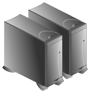
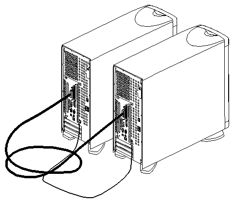
Figure 1-2 shows a rear view of a two-module Origin200 system.
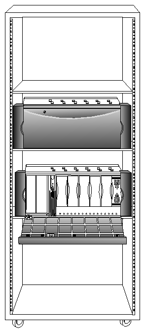
The Origin200 server can also be mounted in a 21-inch Silicon Graphics rack or a standard 19-inch rack. Figure 1-3 shows an example.
Each Origin200 system ships from Silicon Graphics in either a tower (free-standing) or rackmountable configuration. The tower configuration provides extra cosmetic “skins” (side panels and top-cap) and feet. The rackmountable configuration does not have these cosmetic features and feet, but does provide rackmounting slides, mounting ears, a different front bezel, and two pairs of end-caps (for use in 19-inch and 21-inch equipment racks).
If you wish to change your system from a tower configuration to a rack-mountable configuration, or vice versa, contact Silicon Graphics or your local support provider for information about obtaining a conversion kit.
Table 1-1 summarizes the general features of Origin200:
Table 1-1. General Features of Origin200
Feature | One-module System | Two-module System |
|---|---|---|
R10000 processors and cache | 1 or 2 processors each with
separate on-chip instruction and
data caches (32 KB, two-way
set-associative) | 2 to 4 processors |
Memory | 32 MB to 2 GB | 64 MB to 4 GB |
Module system controller | 1 | (Second controller inactive in a two-module system.) |
SCSI channels (internal) | 1, single-ended, Ultra SCSI 1, single-ended, Fast, narrow | 2, single-ended, Ultra SCSI 2, single-ended, Fast, narrow |
5.25-inch drives | 1 full-height, or | 2 full-height, or |
3.5-inch drives | 6, 3.5-inch, Fast-20, wide | 12, 3.5-inch, Fast-20, wide |
Serial ports | 2, RS-232 or RS-422 | 4, RS-232 or RS-422 |
Parallel port | 1 | 2 |
Ethernet | 1, 10-Base-T and 100-Base-TX | 2, 10-Base-T and 100-Base-TX |
AUX port | Serial interface to the module system controller | (Second AUX port inactive in a two-module system.) |
PCI expansion slots | 3, 32 or 64-bit, full-size | 6, 32 or 64-bit, full-size |
Power supply | 1 (480 watt) | 2 (480 watts each) |
For additional information about power requirements, see “Power Supply”. For environmental specifications, including operating and nonoperating conditions, see “Physical and Environmental Specifications”.
The Origin200 logic carrier is a sheet-metal tray that holds:
Together, the logic carrier sheet metal, the main system board, and the PCI backplane form a single, field-replaceable unit.
The logic carrier may be serviced only by Silicon Graphics-trained personnel.
Figure 1-4 shows the complete logic carrier assembly.
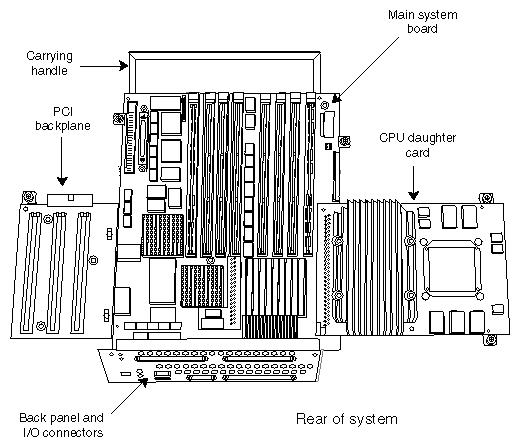
The main system board contains
two SCSI controllers for internal drives
Ethernet controller
two serial port interfaces (UARTs)
parallel port interface
three PCI expansion slots
four banks of two dual-inline memory module (DIMM) sockets (eight total DIMM sockets)
CrayLink Interconnect connector
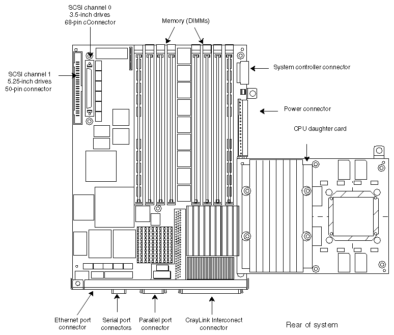
External connectors for the serial, Ethernet, and parallel interfaces, and the CrayLink Interconnect are all mounted directly to the main system board. See Figure 1-5.
Figure 1-5 shows the main system board, the CPU daughter card, and points out the locations of various components.
The module system controller (MSC), located behind the front power switch and status LED, performs the following functions:
holds the system serial number
provides power on, power off, reset, and other low-level functions
displays system status information using a tricolor LED
Power-on, power-off, reset, and nonmaskable interrupts are performed by pressing buttons on the front panel. You can also perform these and other functions by issuing commands to the MSC via a terminal or modem connected to the AUX port at the rear of the system.
See “Front Panel Functions: Status LED, Power, Reset, NMI” in Chapter 4 for a description of the front panel. See “Using the AUX Port and Module System Controller Commands” in Chapter 4 for a description of the commands that the MSC can accept.
There are three expansion slots available for peripheral component interconnect (PCI) bus cards. The slots provide PCI IDs 5, 6, and 7. See Figure 1-6.
Boards can be full-size, 32-bit and 64-bit. In addition to providing 5V, the PCI backplane also accomodates 3.3V PCI cards with up to a total of 30 watts of 3.3V power.
Figure 1-6 shows the location and slot numbers of the PCI backplane.

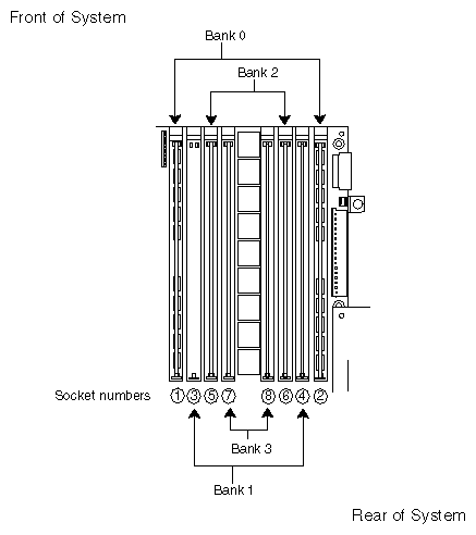
Each Origin200 module can have between 32 MB and 2 GB of memory, depending upon the type of dual in-line memory module (DIMM) that you install. DIMMs are installed in sockets that are grouped into two banks of four sockets each. Figure 1-7 shows the layout of the DIMM sockets on the main system board.
Note the following about installing DIMMs in an Origin200 module:
DIMM sockets are numbered, left to right in Figure 1-7: 1, 3, 5, 7, 8, 6, 4, 2.
DIMMs in each bank must be of the same type, but each bank may have a different type of DIMM.
Interleaving between banks and DIMMs is designed into the memory architecture; you cannot alter the interleaving factors. Maximum interleaving is achieved with a single bank.
The Origin200 server provides bays for two sizes of internal drive options: 5.25-inch drives and 3.5-inch drives.
The 5.25-inch drive bay can be used for two combinations of drive form-factor:
one full-height drive
two half-height drives or two 1-inch drives
The 5.25-inch drives are controlled by SCSI channel 1, and drive IDs are set by jumpers on the drives. Drives are mounted in a removable peripheral carrier, shown in Figure 1-8.

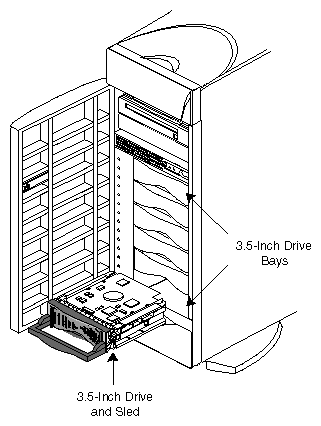
The 3.5-inch drive bay has room for six drives, mounted individually on sleds. The 3.5-inch drives are attached to SCSI channel 0.
Each sled attaches to the 3.5-inch SCSI midplane with SCA connectors. Drive IDs are set by the position of the drive in the drive bay, with ID 1 at the bottom of the drive bay and ID 6 at the top of the drive bay. Figure 1-9 shows a 3.5-inch drive, sled, and drive bay.
There are two SCSI channels in each Origin200 module. Table 1-2 lists the channels in each module and their characteristics.
Table 1-2. SCSI Channel Numbers and Characteristics
First module | Second module | Drives | Description |
|---|---|---|---|
0 | 2 | 3.5-inch | Fast-20 SCSI-II, 16-bit (wide), running at 20 MHz, and capable of transferring 40 MB per second. |
1 | 3 | 5.25-inch | Fast SCSI-II, 8-bit (narrow), running at 10 MHz, and capable of transferring 10 MB per second. |
 | Note: SCSI channels in a one module system are fixed at 0 and 1. The master module in a two-module server also uses channels 0 and 1. However, the slave module channel numbers may vary depending upon the order in which they are detected the first time the system is powered on. See “Determining What Devices are Installed On Your Server” in Chapter 4 for an explanation of device detection and numbering. |
Each Origin200 module provides two serial ports capable of transferring data at speeds ranging from 50 baud to 460 Kbaud. The default serial port configuration is RS-232, but the serial ports can be opened programmatically in RS-422 mode. The serial ports can also be used to send and receive MIDI information.
The serial port connectors are DB-9, male, and are designed to be IBM-compatible. Because of this, they do not use the same pinouts as prior Silicon Graphics DB-9 serial ports.
Table 1-3 lists the serial ports and their correspondence to IRIX device files.
Table 1-3. Serial Port Numbers and Correspondence to IRIX Device Files
Serial Port | IRIX Device File | IRIX Device File | IRIX Device File |
|---|---|---|---|
First module: |
|
|
|
Second module: |
|
|
|
Serial ports in a single-module system, and in the master module are fixed at 1 and 2, with port 1 being the system console. See “Determining What Devices are Installed On Your Server” in Chapter 4 for an explanation of device detection and numbering.
The AUX port is a DIN-8 connector that provides access to the module system controller. See “Using the AUX Port and Module System Controller Commands” in Chapter 4.
Each Origin200 module contains a single RJ-45 connector for 10-Base-T or 100-Base-TX Ethernet. The connector has two integral LEDs that provide basic status. Network speed is automatically negotiated.
| Note: Category 5 wiring is required for proper 100-Base-TX operation. |
Air flow through Origin200 is from the front of the system to the rear, and is drawn by three DC fans located just behind the internal drive bays. Figure 1-10 shows the direction of air flow through Origin200.
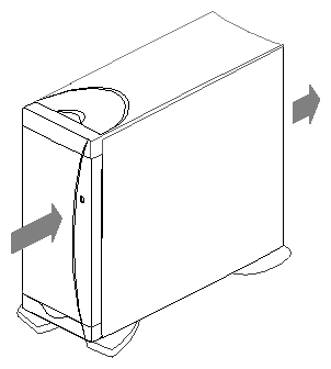
Table 1-4 lists the various physical and environmental specifications of Origin200.
Table 1-4. Origin200 Physical and Environmental Specifications
Specification | Value |
|---|---|
Dimensions |
|
Weight |
|
Environmental (Operating) |
|
Heat dissipation | 2300 BTU per hour, maximum |
If you are installing a two-module system, both modules must be connected to the same, grounded power source (for example, to the same electrical service entrance or breaker box). See “Power Supply” for the amount of current each power supply draws.
Modules may be on separate circuits, but the circuits must be connected to the same power source and ground.
