A real-time program is defined by its close relationship to external hardware. This chapter reviews the ways that IRIX gives you to access and control external devices:
“Device Drivers” summarizes the role that device drivers play in the IRIX system, and points to sources for information on how you can write a device driver.
“SCSI Devices” describes the facilities of the dslib package, with which you can write code to control SCSI devices directly.
“The VME Bus” describes two methods for accessing the most popular interface for real-time devices.
“Serial Ports” summarizes the use of serial ports for real-time input and output.
“External Interrupts” on page 186 summarizes the facilities offered by the External Interrupt device driver.
It is a basic concept in UNIX that all I/O is done by reading or writing files. All I/O devices—disks, tapes, printers, terminals, and VME cards—are represented as files in the file system. Each device is represented by an entry in the /dev file system hierarchy. The purpose of each device special file is to associate a device name with a a device driver, a module of code that is loaded into the kernel either at boot time or dynamically, and is responsible for operating that device at the kernel's request.
 | Note: This section contains an overview for readers who are not familiar with the details of the UNIX I/O system. All these points are covered in much greater detail in the IRIX Device Driver Programming Guide (see “Other Useful Books”). |
When a device special file is created in the /dev file system, it is associated with the device driver that will manage it. The connection between the device name and the device driver is made through major and minor device numbers, which are recorded with the device name in the file system. To see these numbers, try a command such as
ls -l /dev/dsk |
Device creation is documented in the system(4) reference page, the makedev(1) and mknod(1) reference pages, and in the /dev/MAKEDEV script. Device administration is covered in detail in the IRIX Advanced Site and Server Administration Guide.
The major device number selects the device driver. The minor number is passed to the device driver each time it is entered; it encodes such useful parameters as logical unit number or density. In some cases, a device is represented by more than one name in the /dev hierarchy. This associates it with more than one device driver, or else causes the device driver to treat the device differently depending on the name through which it is accessed.
For example, a disk device can appear in both the /dev/dsk and the /dev/rdsk directories, and the same disk can appear under several names in each directory, with each name standing for a different partition of the disk. (The naming of disk devices is documented in the dksc(7) reference page.) Again, a tape drive usually appears multiple times in /dev/mt, with each name receiving different treatment from the tape device driver—names containing “ns,” for example, are written with integers in non-byte-swapped order for compatibility with other systems.
To use a device, a process opens the special device file by passing its pathname to open() (see the open(2) reference page). For example, a generic SCSI device might be opened by a statement such as this.
int scsi_fd = open("/dev/scsi/sc0d11l0",O_RDWR);
|
The returned integer is the file descriptor, a number that indexes an array of control blocks maintained by IRIX in the address space of each process. With a file descriptor, the process can call other system functions that give access to the device. Each of these system calls is implemented in the kernel by transferring control to an entry point in the device driver.
Each device driver supports one or more of the following operations:
Not every driver supports every entry point. For example, the generic SCSI driver (see “Generic SCSI Device Driver”) supports only the open, close, and control entries.
Device drivers in general are documented with the device special files they support, in volume 7 of the reference pages. For a sampling, review:
dsk(7m), documenting the standard IRIX SCSI disk device driver
smfd(7m), documenting the diskette and optical diskette driver
tps(7m), documenting the SCSI tape drive device driver
plp(7), documenting the parallel line printer device driver
klog(7), documenting a “device” driver that is not a device at all, but a special interface to the kernel
If you review a sample of entries in volume 7, as well as other reference pages that are called out in the topics in this chapter, you will understand the wide variety of functions performed by device drivers.
Here is a typical device operation scenario:
A process, running on any CPU, calls read(), write(), or ioctl() requesting a device operation.
After switching to kernel mode and the kernel's address space, the system call enters the device driver's read, write, or control entry point. The system is still executing on behalf of the user process, on the CPU where the call was made.
The device driver initiates an I/O or control action at the device.
Some operations can be completed immediately (in which case go to step 10). Others require a delay while the device operates. The device driver suspends itself with a device driver service routine such as sleep() or psema(). (See the sleep(d3) or psema(d3x) reference pages in IRIX Device Driver Reference Pages.)
Since the current process is suspended, the kernel selects another process to run on the calling CPU.
The I/O action ends with a hardware interrupt, causing the interrupt-handling CPU—which is not necessarily the same CPU that initiated the operation—to enter the device driver's interrupt handler.
The interrupt handler awakens the waiting process with a device driver service routine such as wakeup() or vsema(). (See the IRIX Device Driver Reference Pages.)
The interrupt handler possibly initiates another I/O action.
The process that requested the operation is now dispatchable, and the kernel schedules it to run, based on its priority, affinity, and other factors (“Scheduling Concepts”).
The process executes the final instructions in the device driver code and switches mode back to the user address space, the function complete.
When your program needs direct control of a device, you have the following choices:
If it is a device for which IRIX or the device manufacturer distributes a device driver, find the device driver reference page in volume 7 to learn the device driver's support for read(), write(), mmap(), and ioctl(). Use these functions to control the device.
If it is a VME device without bus master capability, you can control it directly from your program using programmed I/O or user-initiated DMA. Both options are discussed under “The VME Bus”.
If it is a VME device with bus master (on-board DMA) capability, you should receive an IRIX device driver from the OEM. Consult the IRIX Advanced Site and Server Administrator Guide to install the device and its driver. Read the OEM reference page to learn the device driver's support for read(), write(), and ioctl().
If it is a SCSI device that does not have built-in IRIX support, you can control it from your own program using the generic SCSI device driver. See “Generic SCSI Device Driver” on page 175.
In the remaining case, you have a device with no driver. In this case you must create a device driver. This process is documented in the IRIX Device Driver Programmer's Guide, which contains extensive information and sample code.
A device driver operates in the kernel domain and uses a large number of kernel functions that are not available to normal processes—for example, the device driver has to be able to map a buffer in the user process address space into the kernel address space and then into real memory so that it can be used for I/O. The IRIX Device Driver Reference Pages document these kefunctions.
The SCSI interface is the principal way of attaching disk, cartridge tape, CD-ROM, and digital audio tape (DAT) devices to the system. It can be used for other kinds of devices, such as scanners and printers.
IRIX contains device drivers for disk and tape. Other SCSI devices are controlled through a generic device driver that must be extended with programming for a specific device.
Two SCSI-2 controllers are incorporated in each POWER Channel-2 board. Additional controllers can be added in two groups of 3 on HIO modules, for a maximum of 8 controllers per channel. The SCSI controllers are DMA devices that make near-optimum use of the POWER Channel-2 bus bandwidth.
Using 8-bit data transfers, a data rate of approximately 7 megabytes per second can be reached, per controller. Using 16-bit SCSI, data rates near 14 MB per second can be achieved, per controller.
| Note: These data rates can be achieved by configuring the system to perform DMA directly into the requesting process's address space without buffering. This requires the use of Direct file access for disk files (see “Synchronous Writing and Direct Writing”). The generic SCSI device driver also performs DMA directly in or out of the process's buffers (see “Generic SCSI Device Driver”). |
All controllers are capable of differential output and so can be cabled longer distances from the system cabinet.
The detailed, board-level programming of the host SCSI adapters is done by an IRIX-supplied host adapter driver. The services of this driver are available to the SCSI device drivers that manage the logical devices. The host adapter drivers handle the low-level communication over the SCSI interface, such as programming the SCSI interface chip or board, negotiating synchronous or wide mode, and handling disconnect/reconnect. SCSI device drivers call on host adapter drivers using indirect calls through a table of adapter functions.
The naming conventions for disk and tape device files are documented in the intro(7) reference page. In general, devices in /dev/[r]dsk are disk drives, and devices in /dev/[r]mt are tape drives.
Disk devices in /dev/[r]dsk are operated by the SCSI disk controller, which is documented in the dks(7) reference page. It is possible for a program to open a disk device and read, write, or memory-map it, but this is almost never done. Instead, programs open, read, write, or map files; and the EFS or XFS file system interacts with the device driver.
Tape devices in /dev/[r]mt are operated by the magnetic tape device driver, which is documented in the tps(7) reference page. Users normally control tapes using such commands as tar and mt (see the tar(1) and mt(1) reference pages), but it is also common for programs to open a tape devices and then to use read(), write(), and ioctl() to interact with the device driver.
Since the tape device driver supports the read/write interface, you can schedule tape I/O through the asynchronous I/O interface (see “Asynchronous I/O Basics”). You need to take pains to ensure that asynchronous writes to a tape are executed in the proper sequence; see “Multiple Operations to One File” on page 156.
Generally, non-disk, non-tape SCSI devices are installed in the /dev/scsi directory. Devices so named are controlled by the generic SCSI device driver, which is documented in the ds(7m) reference page.
Unlike most kernel-level device drivers, the generic SCSI driver does not support interrupts, and does not support the read() and write() functions. Instead, it supports a wide variety of ioctl() functions that you can use to issue SCSI commands to a device. In order to invoke these operations you prepare a dsreq structure describing the operation and pass it to the device driver. Operations can include input and output as well as control and diagnostic commands.
The programming interface supported by the generic SCSI driver is quite primitive. A library of higher-level functions makes it easier to use. This library is documented in the dslib(3x) reference page. The most important functions in it are listed below:
dsopen(), which takes a device pathname, opens it for exclusive access, and returns a dsreq structure to be used with other functions.
fillg0cmd(), fillg1cmd(), and filldsreq(), which simplify the task of preparing the many fields of a dsreq structure for a particular command.
doscsireq(), which calls the device driver and checks status afterward.
The dsreq structure for some operations specifies a buffer in memory for data transfer. The generic SCSI driver handles the task of locking the buffer into memory (if necessary) and managing a DMA transfer of data.
When the ioctl() function is called (through doscsireq() or directly), it does not return until the SCSI command is complete. You should only request a SCSI operation from a process that can tolerate being blocked.
Upon the basic dslib functions are built several functions that execute specific SCSI commands, for example, read08() performs a read. However, there are few SCSI commands that are recognized by all devices. Even the read operation has many variations, and the read08() function as supplied is unlikely to work without modification. The dslib library functions are not complete. Instead, you must alter them and extend them with functions tailored to a specific device.
The source for dslib, and some example programs that use dslib, can be found in the 4DGifts distribution, in /usr/people/4Dgifts/examples/devices/devscsi.
A library of functions that enable you to read audio data from an audio CD in the CD-ROM drive is distributed with IRIX. This library was built upon the generic SCSI functions supplied in dslib. The CD audio library is documented in the cdintro(3) reference page.
A library of functions that enable you to read and write audio data from a digital audio tape is distributed with IRIX. This library was built upon the functions of the magnetic tape device driver. The DAT audio library is documented in the DTintro(3) reference page.
Each CHALLENGE XL, POWER CHALLENGE, or Onyx system includes full support for the VME interface, including all features of Revision C.2 of the VME specification, and the A64 and D64 modes as defined in Revision D. VME devices can access system memory addresses, and devices on the system bus can access addresses in the VME address space.
The naming of VME devices in /dev/vme, and other administrative issues, are covered in the usrvme(7) reference page.
A number of special terms are used to describe the multiprocessor CHALLENGE support for VME. The terms are described in the following list. Their relationship is shown graphically in Figure 9-1.
POWERpath-2 Bus | The primary system bus, connecting all CPUs and I/O channels to main memory. |
POWER Channel-2 | The circuit card that interfaces one or more I/O devices to the POWERpath-2 bus. |
F-HIO card | Adapter card used for cabling a VME card cage to the POWER Channel |
VMECC | VME control chip, the circuit that interfaces the VME bus to the POWER Channel. |
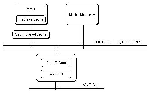
All multiprocessor CHALLENGE systems contain a 9U VME bus in the main card cage. Systems configured for rack-mount can optionally include an auxiliary 9U VME card cage, which can be configured as 1, 2, or 4 VME busses. The possible configurations of VME cards are shown in Table 9-1
Table 9-1. Multiprocessor CHALLENGE VME Cages and Slots
Model | Main Cage | Aux Cage Slots | Aux Cage Slots | Aux Cage Slots |
|---|---|---|---|---|
Challenge L | 5 | n.a. | n.a. | n.a. |
Onyx Deskside | 3 | n.a. | n.a. | n.a. |
Challenge XL | 5 | 20 | 10 and 9 | 5, 4, 4, and 4 |
Onyx Rack | 4 | 20 | 10 and 9 | 5, 4, 4, and 4 |
Each VME bus after the first requires an F cable connection from an F-HIO card on a POWER Channel-2 board, as well as a Remote VCAM board in the auxiliary VME cage. Up to three VME busses (two in the auxiliary cage) can be supported by the first POWER Channel-2 board in a system. A second POWER Channel-2 board must be added to support four or more VME busses. The relationship among VME busses, F-HIO cards, and POWER Channel-2 boards is detailed in Table 9-2.
Table 9-2. POWER Channel-2 and VME bus Configurations
Number of VME Busses | PC-2 #1 | PC-2 #1 | PC-2 #2 | PPC-2 #2 |
|---|---|---|---|---|
1 | unused | unused | n.a. | n.a. |
2 | F-HIO short | unused | n.a. | n.a. |
3 (1 PC-2) | F-HIO short | F-HIO short | n.a. | n.a. |
3 (2 PC-2) | unused | unused | F-HIO | unused |
4 | unused | unused | F-HIO | F-HIO |
5 | unused | unused | F-HIO | F-HIO |
F-HIO short cards, which are used only on the first POWER Channel-2 board, supply only one cable output. Regular F-HIO cards, used on the second POWER Channel-2 board, supply two. This explains why, although two POWER Channel-2 boards are needed with four or more VME busses, the F-HIO slots on the first POWER Channel-2 board remain unused.
A device on the VME bus has access to an address space in which it can read or write. Depending on the device, it uses 16, 32, or 64 bits to define a bus address. The resulting numbers are called the A16, A32, and A64 address spaces.
There is no direct relationship between an address in the VME address space and the set of real addresses in the Challenge/Onyx main memory. An address in the VME address space must be translated twice:
The VMECC and POWER Channel devices establish a translation from VME addresses into addresses in real memory.
The IRIX kernel assigns real memory space for this use, and establishes the translation from real memory to virtual memory in the address space of a process or the address space of the kernel.
Address space mapping is done differently for programmed I/O, in which slave VME devices respond to memory accesses by the program, and for DMA, in which master VME devices read and write directly to main memory.
In order to allow programmed I/O, the mmap() system function establishes a correspondence between a segment of a process's address space and a segment of the VME address space. The mmap() function, or the equivalent kernel functions that are available to device drivers, program registers in the VMECC to recognize fetches and stores to main memory real addresses and to translate them into reads and writes on the VME bus. The devices on the VME bus must react to these reads and writes as slaves; DMA is not supported by this mechanism.
One VMECC can map as many as 16 different segments of memory. Each segment can be as long as 8 MB. The segments can be used singly or in any combination. Thus one VMECC can support 16 unique mappings of at most 8 MB, or a single mapping of 128 MB, or combinations between.
DMA mapping is based on the use of page tables stored in system main memory. This allows DMA devices to access the virtual addresses in the address spaces of user processes. The real pages of a DMA buffer can be scattered in main memory, but this is not visible to the DMA device. DMA transfers that span multiple, scattered pages can be performed in a single operation.
The kernel functions that establish the DMA address mapping are available only to device drivers. For information on these, refer to the IRIX Device Driver Programmer's Guide.
Each DMA stream from the VME bus is assigned a virtual base address in VME address space which corresponds to a pointer to the beginning of a page table in main memory. Bits 20 through 12 of the VME virtual address are used as the virtual page number (VPN), an offset into the page table (I/O operations always use 4 KB pages, regardless of the page size of process address spaces). The page table entry is used as the page address in main memory.
The hardware of the POWER Channel-2 supports up to 8 DMA streams simultaneously active on a single VME bus without incurring a loss of performance.
Your program accesses the devices on the VME bus in one of two ways, through programmed I/O (PIO) or through DMA. Normally, VME cards with Bus Master capabilities always use DMA, while VME cards with slave capabilities are accessed using PIO.
The Challenge/Onyx architecture also contains a unique hardware feature, the DMA Engine, which can be used to move data directly between memory and a slave VME device.
You perform PIO to VME devices by mapping the devices into memory using the mmap() function (see “Mapping a VME Device”).
PIO is suitable for applications that transfer small amounts of data. It is especially suitable for polling a large number of low-bandwidth devices. The bandwidth available for PIO is limited because PIO access cannot be pipelined. The entire path from the CPU through the POWER Channel-2 and VMECC to the VME bus remains occupied from the time a PIO input starts until it completes. (In contrast, DMA transfers are expedited by data prefetching, which is done in the hardware.)
Each PIO read requires two transfers over the POWERpath-2 bus: one to send the address to be read, and one to retrieve the data. The latency of a single PIO input is approximately 4 microseconds. PIO write is somewhat faster, since the address and data are sent in one operation. Typical PIO performance is summarized in Table 9-3.
Table 9-3. VME Bus PIO Bandwidth
Data Unit Size | Read | Write |
|---|---|---|
D8 | 0.2 MB/second | 0.75 MB/second |
D16 | 0.5 MB/second | 1.5 MB/second |
D32 | 1 MB/second | 3 MB/second |
When a system has multiple VME busses, you can program concurrent PIO operations from different CPUs to different busses, effectively multiplying the bandwidth by the number of busses. It does not improve performance to program concurrent PIO to a single VME bus.
 | Tip: When transferring more than 32 bytes of data, you can obtain higher rates using the DMA Engine. See “DMA Engine Access to Slave Devices”. |
VME bus cards with Bus Master capabilities transfer data using DMA. These transfers are controlled and executed by the circuitry on the VME card. The DMA transfers are directed by the address mapping described under “DMA Mapping”.
DMA transfers from a Bus Master are always initiated by a kernel-level device driver. In order to exchange data with a VME Bus Master, you open the device and use read() and write() calls. The device driver sets up the address mapping and initiates the DMA transfers. The calling process is typically blocked until the transfer is complete and the device driver returns.
The typical performance of a single DMA transfer is summarized in Table 9-4.
Table 9-4. VME Bus Bandwidth, VME Master Controlling DMA
Data Transfer Size | Reading | Writing |
|---|---|---|
D8 | 0.4 MB/sec | 0.6 MB/sec |
D16 | 0.8 MB/sec | 1.3 MB/sec |
D32 | 1.6 MB/sec | 2.6 MB/sec |
D32 BLOCK | 22 MB/sec (256 byte block) | 24 MB/sec (256 byte block) |
D64 BLOCK | 55 MB/sec (2048 byte block) | 58 MB/sec (2048 byte block) |
Up to 8 DMA streams can run concurrently on each VME bus. However, the aggregate data rate for any one VME bus will not exceed the values in Table 9-4.
A DMA engine is included as part of each POWER Channel-2. The DMA engine is unique to the Challenge/Onyx architecture. It performs efficient, block-mode, DMA transfers between system memory and VME bus slave cards—cards that would normally be capable of only PIO transfers.
The DMA engine greatly increases the rate of data transfer compared to PIO, provided that you transfer at least 32 contiguous bytes at a time. The DMA engine can perform D8, D16, D32, D32 Block, and D64 Block data transfers in the A16, A24, and A32 bus address spaces.
All DMA engine transfers are initiated by a special device driver. However, you do not access this driver through open/read/write system functions. Instead, you program it through a library of functions. The functions are documented in the udmalib(3x) reference page. They are used in the following sequence:
Call dma_open() to initialize action to a particular VME card.
Call dma_allocbuf() to allocate storage to use for DMA buffers.
Call dma_mkparms() to create a descriptor for an operation, including the buffer, the length, and the direction of transfer.
Call dma_start() to execute a transfer. This function does not return until the transfer is complete.
The performance of the DMA engine for D32 transfers is summarized in Table 9-5. Performance with D64 Block transfers is somewhat less than twice the rate shown in Table 9-5. Transfers for larger sizes are faster because the setup time is amortized over a greater number of bytes.
Table 9-5. VME Bus Bandwidth, DMA Engine, D32 Transfer
Transfer Size | Read | Write | Block Read | Block Write |
|---|---|---|---|---|
32 | 2.8 MB/sec | 2.6 MB/sec | 2.7 MB/sec | 2.7 MB/sec |
64 | 3.8 MB/sec | 3.8 MB/sec | 4.0 MB/sec | 3.9 MB/sec |
128 | 5.0 MB/sec | 5.3 MB/sec | 5.6 MB/sec | 5.8 MB/sec |
256 | 6.0 MB/sec | 6.7 MB/sec | 6.4 MB/sec | 7.3 MB/sec |
512 | 6.4 MB/sec | 7.7 MB/sec | 7.0 MB/sec | 8.0 MB/sec |
1024 | 6.8 MB/sec | 8.0 MB/sec | 7.5 MB/sec | 8.8 MB/sec |
2048 | 7.0 MB/sec | 8.4 MB/sec | 7.8 MB/sec | 9.2 MB/sec |
4096 | 7.1 MB/sec | 8.7 MB/sec | 7.9 MB/sec | 9.4 MB/sec |
The dma_start() function operates in user space; it is not a kernel-level device driver. This has two important effects. First, overhead is reduced, since there are no mode switches between user and kernel, as there are for read() and write(). This is important since the DMA engine is often used for frequent, small inputs and outputs.
Second, dma_start() does not block the calling process, in the sense of suspending it and possibly allowing another process to use the CPU. It waits in a test loop until the operation is complete. As you can infer from Table 9-5, typical transfer times range from 50 to 250 microseconds. You can calculate the approximate duration of a call to dma_start() based on the amount of data and the operational mode.
You can use the udmalib functions to access a VME Bus Master device, if the device can respond in slave mode. However, this would normally be less efficient than using the Master device's own DMA circuitry.
While you can initiate only one DMA engine transfer per bus, it is possible to program a DMA engine transfer from each bus in the system, concurrently.
Occasionally a real-time program has to use an input device that interfaces through a serial port. This is not a recommended practice for several reasons: the serial device drivers and the STREAMS modules that process serial input are not optimized for deterministic, real-time performance; and at high data rates, serial devices generate many interrupts.
When there is no alternative, a real-time program will typically open one of the files named /dev/tty*. The names, and some hardware details, for these devices are documented in the serial(7) reference page. Information specific to two serial adapter boards is in the duart(7) reference page and the cdsio(7) reference page.
When a process opens a serial device, a line discipline STREAMS module is pushed on the stream by default. If the real-time device is not a terminal and doesn't support the usual line controls, this module can be removed. Use the I_POP ioctl (see the streamio(7) reference page) until no modules are left on the stream. This minimizes the overhead of serial input, at the cost of receiving completely raw, unprocessed input.
An important feature of current device drivers for serial ports is that they try to minimize the overhead of handling the many interrupts that result from high character data rates. The serial I/O boards interrupt at least every 4 bytes received, and in some cases on every character (at least 480 interrupts a second, and possibly 1920, at 19,200 bps). Rather than sending each input byte up the stream as it arrives, the drivers buffer a few characters and send multiple characters up the stream.
When the line discipline module is present on the stream, this behavior is controlled by the termio settings, as described in the termio(7) reference page for non-canonical input. However, a real-time program will probably not use the line-discipline module. The hardware device drivers support the SIOC_ITIMER ioctl that is mentioned in the serial(7) reference page, for the same purpose.
The SIOC_ITIMER function specifies the number of clock ticks (see “Tick Interrupts”) over which it should accumulate input characters before sending a batch of characters up the input stream. A value of 0 requests that each character be sent as it arrives (do this only for devices with very low data rates, or when it is absolutely necessary to know the arrival time of each input byte). A value of 5 tells the driver to collect input for 5 ticks (50 milliseconds, or as many as 24 bytes at 19,200 bps) before passing the data along.
The Challenge/Onyx hardware includes support for generating and receiving external interrupt signals. Four jacks for outgoing signals are available on the master IO4 board. Your program can change the level of these lines individually. Two jacks for incoming interrupt signals are also provided. The input lines are logically OR'd together and presented as a single interrupt; your program cannot distinguish one input line from another.
The electrical interface to the external interrupt lines is documented at the end of the ei(7) reference page.
Your program controls and receives external interrupts by interacting with the external interrupt device driver. This driver is associated with the special device file /dev/ei, and is documented in the ei(7) reference page. (External interrupt support and the ei(7) page are first available in IRIX 5.3.)
Your program can generate an outgoing signal on any one of the four external interrupt lines. To do so, it first opens /dev/ei. Then it can use ioctl() on the file descriptor to switch the outgoing lines. The principal functions are summarized in Table 9-6.
Table 9-6. Generating Outgoing External Signals
Operation | Typical ioctl() Call |
|---|---|
Set pulse width to N microseconds | ioctl(eifd, EIIOCSETOPW, N); |
Send a pulse on line L (L is 0, 1, 2, or 3) | ioctl(eifd, EIIOCSTROBE, 1<<L) |
Set line L high (active, asserted) | ioctl(eifd, EIIOCSETHI, 1<<L) |
Set line L low (inactive, deasserted) | ioctl(eifd, EIIOCSETLO, 1<<L) |
The external interrupt lines are controlled directly from a CPU; they are not managed by a chip or I/O controller. In order to ensure precise, repeatable pulse widths, the device driver generates a pulse by asserting the line, then spinning in a disabled loop until the specified pulse time has elapsed, and deasserting the line. Clearly, if the pulse width is set to much more than the default of 5 microseconds, pulse generation could interfere with the handling of other interrupts (see “Kernel Critical Sections”).
The calls to assert and deassert the outgoing lines do not tie up the kernel. However, it is usually not practical for even a real-time program to hope to generate repeatable pulse durations by this method—at least, not with duty cycles measured in microseconds. For one thing, the minimum guaranteed interrupt service time is 200 microseconds (see “Minimizing Interrupt Response Time”). If an interrupt occurs between the call to assert the signal and the call to deassert it, the pulse width can be stretched by 200 microseconds or more. Direct assertion of the outgoing signal should be used only when the desired signal frequency and pulse duration are measured in milliseconds.
An important feature of the external interrupt input line is that interrupts are triggered by the level of the signal, not by the transition from deasserted to asserted. This means that, whenever external interrupts are enabled and any of the input lines are in the asserted state, an external interrupt occurs. The interface between your program and the external interrupt device driver is affected by this hardware design.
The external interrupt handler maintains two important numbers:
the expected input pulse duration in microseconds
the minimum pulse-to-pulse interval, called the “stuck” pulse width because it is used to detect when an input line is “stuck” in the asserted state
When the external interrupt device driver is entered to handle an interrupt, it spins in a disabled loop until the expected input pulse duration has expired. At the end of this time the interrupt handler counts one external interrupt and returns to the kernel, which enables interrupts and returns to the interrupted process.
Normally the input line will be deasserted during the period the interrupt handler was spinning. However, if the input line is still asserted when the time expires, another external interrupt will occur immediately. The external interrupt handler notes that it has been reentered within the “stuck” pulse time since the last interrupt. It assumes that this is still the same input pulse as before. In order to prevent the stuck pulse from saturating the CPU with interrupts, the interrupt handler disables the external interrupt signal.
External interrupts remain disabled for one timer tick (“Tick Interrupts”). Then the external interrupt device driver reenables external interrupts. If an interrupt occurs immediately, the input line is still asserted. The handler disables external interrupts for another, longer delay. It continues to delay and to test the input signal in this manner until it finds the signal deasserted.
You can set the expected input pulse width and the minimum pulse-to-pulse time using ioctl(). For example, you could set the expected pulse width using a function like Example 9-1.
int setEIPulseWidth(int eifd, int newWidth)
{
   int oldWidth;
   if ( (0==ioctl(eifd, EIIOCGETIPW, &oldWidth))
   &&   (0==ioctl(eifd, EIIOCSETIPW, newWidth)) )
      return oldWidth;
   perror("setEIPulseWidth");
   return 0;
}
|
The function retrieves the original pulse width and returns it. If either ioctl() call fails, it returns 0.
The default pulse width is 5 microseconds.Pulse widths shorter than 2.5 microseconds are not recommended.
Since the interrupt handler keeps interrupts disabled for this duration, you want to specify as short an expected width as possible. However, it is very important that all legitimate input pulses terminate within the expected time. When a pulse persists past the expected time, the interrupt handler is likely to detect a “stuck” pulse, and disable external interrupts for several milliseconds. Set the expected pulse width to a few microseconds longer than the longest valid pulse.
You can set the minimum pulse-to-pulse width using code like that in Example 9-1, using constants EIIOCGETSPW and EIIOCSETSPW.
The device driver notes the time of any legitimate signal that it detects. When another interrupt occurs within the “stuck” time following, the interrupt handler assumes it represents the same pulse as before. It discards the interrupt and disables interrupts for a time.
The default stuck-pulse time is 500 microseconds. You want to set this time to the nominal pulse-to-pulse interval, minus the largest amount of “jitter” that you anticipate in the signal. In the event that external signals are not produced by a regular oscillator, set this value to the expected pulse width plus the duration of the shortest expected “off” time, with a minimum of twice the expected pulse width.
For example, suppose you expect the input signal to be a 10 microsecond pulse at 1000 Hz, both numbers plus or minus 10%. Set the expected pulse width to 11 or 12 microseconds to ensure that all pulses are seen to complete. Set the stuck pulse width to 900 microseconds, so as to permit a legitimate pulse to arrive 10% early.
The external interrupt device driver offers you three different methods of receiving notification of an interrupt. You can
have a signal of your choice delivered to your process
execute an ioctl() call that polls for an interrupt, or that blocks until one is received
call a library function that polls for an interrupt, or that spin-loops until one is received
You would use a signal when interrupts are infrequent and irregular, and when it is not important to know the precise arrival time. Signal latency can be milliseconds long in some cases (see “Signal Delivery and Latency”). For this reason, it would not be wise to use signals to handle a high rate of interrupts, nor to expect to time interrupts closely. Use a signal when, for example, the external interrupt represents a human-operated switch or some kind of out-of-range alarm condition.
The ioctl(EIIOCRECV) call tests for an interrupt, or suspends the caller until an interrupt arrives or a timeout expires (see the ei(7) reference page for details). Use this method when interrupts arrive frequently enough that it is worthwhile devoting a process to handling them.
The ioctl() call is a fairly costly method of polling, since it entails entry to and exit from the kernel. This is not significant if the polling is infrequent—for example, if one poll call is made every 60th of a second.
When the ioctl() call is used to wait for an interrupt, an unknown amount of time can pass between the moment when the interrupt handler unblocks the process, and the moment when the kernel dispatches the process. This makes it impossible to timestamp the interrupt at the microsecond level.
For minimum latency, a library function eicbusywait() is provided (see the ei(7) reference page). This function does not switch into kernel mode, so it is a very fast method of polling for an interrupt. However, if you ask it to wait until an interrupt occurs, it waits by spinning on a repeated test for an interrupt. This monopolizes the CPU, so this form of waiting can only be used reliably by a process running in an isolated, nonpreemptive CPU. (If there are other processes to run, or interrupts to handle, the polling loop in eicbusywait() shares the CPU and can be preempted for long periods.)
The benefit of eicbusywait() is that, in an isolated, nonpreemptive CPU, control returns to the calling process in negligible time after the interrupt handler has exited, so the interrupt can be handled quickly and timed precisely.