This appendix contains instructions for configuring the SMT daemon and the FDDIXPress driver with site-specific (nondefault) settings.
The SMT daemon can be configured for three kinds of parameters: SMT station, MAC, and PHY parameters.
 | Note: Only FDDI experts should change the SMT daemon configuration. Many of these parameters can have disastrous effects on the FDDI ring. It is relatively easy to make the entire FDDI ring dysfunctional if these parameters are set incorrectly. |
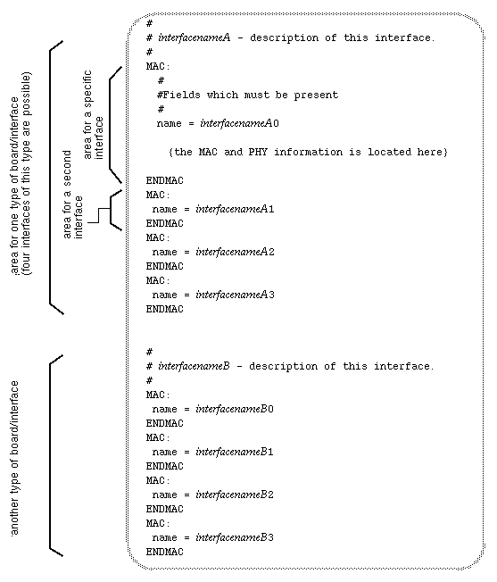
The SMT daemon configuration file is /etc/fddi/smtd.conf. The file is organized into two types of sections, as illustrated in Figure C-1 and described below:
The station section (labeled SMT_STATION ) has one area (labeled station #) for each instance of an FDDI network interface on the station, up to four.
The numerous FDDI board sections are each labeled with an FDDI interface name (for example, xpi , rns, or ipg). There is one board section for each type of FDDI board supported by Silicon Graphics. Each type-of-board section has four subareas: one subarea for each instance (network interface) of that type (for example, ipg0, ipg1, ipg2, ipg3). Each subarea can contain parameters for one MAC and, for each MAC, one or more PHYs.

The SMT_STATION section of the smtd.conf looks like Figure C-2. Before any alteration has been made to this file, the station parameters are listed only under the first instance (station 0), and they are marked with a pound sign (commented out) indicating that they are not currently used for configuration. When the file looks like this, each FDDI network interface is configured with default station settings, as summarized in Table C-1.

Once the file has been altered to contain uncommented parameters, the SMT daemon is configured to use those settings with the network interface that corresponds to that station section. The manner in which the smtd.conf sections (station 0, station 1, and so on) are matched to network interfaces is detailed below:
The network configuration script (/etc/init.d/network) uses the settings located under station 0 to configure the first FDDI network interface it sets up.
You can discover the order in which a station's network interfaces are configured with the command /usr/etc/netstat -i.
The script uses the settings under station 1 for the next FDDI network interface it configures, and so on, up to the fourth.
The default settings for station parameters are summarized in Table C-1.
Explanations for changing the settings are listed immediately after the table. Whenever a parameter matches a parameter in one of the FDDI standards, the official FDDI name is shown in parentheses (fddiname).
Table C-1. smtd.conf: Station Parameter Defaults
Parameter | Default Setting | Description |
|---|---|---|
StationId | 00-00-MAC address | Forces SMT StationID to be this value. |
StationType | read from hardware | Station type: |
srf_on | 1 | Status report protocol (SRF) on/off: |
trace_on | 1 | Trace function on/off: |
reportlimit | 5 | Maximum number of status report frames transmitted during a reset. |
pathavail | 3 | SMT paths available: |
conf_cap | 2 | Configuration capabilities: |
conf_policy | 0 | Configuration policy: |
conn_policy | 32768 | SMT connection policy: |
t_notify | 30 | Seconds for holding reset. |
pmf_on | 0 | Parameter management protocol (PMF) on/off: |
vers_op | varies | SMT operational version. |
sr_mid | 01:80:c2:00:01:10 | Status report protocol (SRF) multicast address. |
user_data | none | Text entry available for customer to use. |
To change one or more of the station parameters, follow these steps:
Open the /etc/fddi/smtd.conf file with your favorite editor.
Locate the line containing the parameter you want to alter.
If you are configuring a second, third, or fourth FDDI interface, copy the entire line into the area associated with the network interface you want to configure.
Uncomment the line by removing the leftmost pound sign (#). Do not remove the other pound sign (in the center portion of the line) that marks the parameter's description.
Alter the setting of the parameter.
Save the file.
Stop, then restart the network interface, with the commands below:
% su
Password: thepassword
# smtconfig interfacename down
# smtconfig interfacename up
StationId (fddiSMTStationId) |
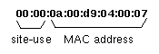
An 8-byte identification number displayed in canonical order. The least significant six bytes must be a universally administered address (that is, the MAC address). The most significant two bytes can be assigned at each site. FDDIXPress (by default) uses the MAC address of the first MAC (MAC0) for the lower six bytes and zeros for the upper two, as illustrated in Figure C-3. The entry is in hexadecimal characters where bytes are separated by colons (for example, 00:01:0a:00:d9:04:00:07).
StationType |
Identifies the type of device associated with this interface:
0=single-attachment station (SAS)
1=single-attachment concentrator (SAC)
2=single-MAC, dual-attachment station, (SM_DAS)
3=dual-MAC, dual-attachment station (DM_DAS)
srf_on (fddiSMTStatRptPolicy) |
A switch to turn Status Report Frame protocol (SRF) on and off. SRF is used by a station to periodically announce its status (for example, a change in configuration, initiation of a trace event, detection of an illegal connection). This functionality is useful to other SMTs for maintaining the ring.
0=disable
1=enable
trace_on |
A switch to turn Trace capabilities on and off. The trace function is one of the basic FDDI methods for recovering a disfunctional ring.
0=disable
1=enable
reportlimit |
The maximum number of status report frames (SRFs) that can be sent during a board reset. The entry is a decimal digit equal to or greater than 0.
pathavail (fddiSMTPathsAvailable) |
This setting defines the path (or paths) available to the SMT on this station for communicating with other SMTs. Each path consists of a communication route: one media connection, one PHY, and one MAC. The primary and secondary paths usually, but not necessarily, correspond to connections to the primary and secondary rings. The local path is a route by which the SMT can access other SMTs without using the main trunk ring. Each increase in the pathavail setting adds an additional path; for example, when the setting is 3, primary and secondary paths are available as well as an alternate, local path.
Settings 0-2 are dynamically overidable, but 3 is not. When the entry is 0, 1, or 2, the actual connection to the ring overides the file setting, and the SMT daemon is allowed to use whatever paths are identified. For example, if the entry in the smtd.conf file is 0 but two paths are found, the SMT daemon will have both a primary and secondary path available. The 3 (local) setting cannot be overidden. For example, if the setting is 2, the local path will not be made available, even if the path actually exists.
0=isolated
1=primary
2=secondary
3=local
conf_cap (fddiSMTConfigCapabilities) |
The configuration capabilities for this MAC. These items apply only to dual-attachment devices; the settings are ignored for single-attachment devices.
1=holdavail (prevents wrapping when a fault occurs)
2=wrap_ab (a dual-homed connection)
3=both
conf_policy (fddiSMTConfigPolicy) |
The configuration policy for this MAC. For this configuration to be set up, the selected items must be supported (as set in the conf_cap parameter).
0=configuration hold
conn_policy (fddiSMTConnectionPolicy) |
The connection policy for the MAC. The selections are controlled by a 16-bit register in which each bit controls one policy. One or more of the bits can be set. The entry in the configuration file must be a decimal numeral representing the value of the 16-bit binary sequence with all the desired bits set to one. For example, if you want to set bits 0 and 1 (binary 0000 0000 0000 0011), assign a 3 to conn_policy. Below are the meanings for each bit when it is set to one:
bit 0: reject AA
bit 1: reject AB
bit 2: reject AS
bit 3: reject AM
bit 4: reject BA
bit 5: reject BB
bit 6: reject BS
bit 7: reject BM
bit 8: reject SA
bit 9: reject SB
bit 10: reject SS
bit 11: reject SM
bit 12: reject MA
bit 13: reject MB
bit 14: reject MS
bit 15: reject MM
| Note: The most significant bit (bit 15) must always be set. |
pmf_on |
Switch to turn Parameter Management protocol (PMF) on and off. PMF makes it possible for SMTs to ask for and receive MIB information about other stations on the ring. The protocol also allows SMTs to alter some of the information in other stations' MIBs.
0=disable
1=enable
vers_op (fddiSMTOpVersionId) |
The SMT version to which this SMT daemon conforms. This entry should not be altered.
sr_mid |
Address used for Status Report Frame protocol (SRF) multicast group communication. The default entry is the address specified in the SMT standard and should not be altered.
user_data (fddiSMTUserData) |
User data that, if defined, is included in the SMT Info field of each SMT frame's header. The entry can be up to 32 characters (blank spaces are allowed and are counted as characters); quotation marks are not required.
The board sections of the smtd.conf file are labeled with the name of the network interface (for example, ipg , rns, or xpi) for that type of board. There is one section for each type of FDDI board supported by Silicon Graphics. Figure C-4 illustrates two type-of-board sections; however, there is no limit to these kinds of sections.
Each type-of-board section contains four specific network interface areas. The file must contain one network interface area for each MAC of that type installed into the station (for example, xpi0, xpi1, xpi2, xpi3). One MAC parameter and one or more PHY parameters can be placed into each of the specific interface areas.
The MAC section of the smtd.conf file looks like Figure C-5. Each MAC section configures one MAC.
Unlike the other sections of this file, the MAC area contains a required line. This line, identified by arrows in Figure C-5, must never be missing and must contain a valid FDDI network interface name.
Before any alteration has occurred, the MAC parameters are listed only once, under the first specific-interface area of the first type-of-board section. All but one of the parameters are marked with a pound sign (commented out), indicating that they are not currently used for configuration. The single, uncommented line (name=interfacename) must never be removed or commented out; this line is required. When the file looks like this, the SMT daemon is configured with default settings, as summarized in Table C-2.
When a board has more than one MAC, there can be one MAC section for each MAC. In these configurations, each MAC section must have a unique entry for name=interfacename.
Explanations for changing the MAC settings are listed immediately after the table. Whenever a parameter matches a parameter in one of the FDDI standards, the official FDDI name is shown in parentheses (fddiname).
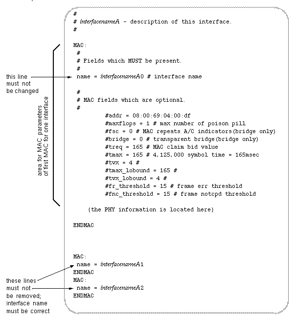
Table C-2. smtd.conf: MAC Parameter Defaults
Parameter | Default Setting | Description |
|---|---|---|
addr | read from hardware | MAC address in canonical order |
maxflops | 1 | Maximum number of times the board can be reset |
fsc | 0 | Frame Status Capabilities: (set only on bridges): |
bridge | 0 | Bridge type (set only for bridges): |
treq | 165 | MAC claim bid value: |
tmax | 165 | Maximum bid supported: |
tvx | 4 | Valid transmission timer: |
tmax_lobound | 165 | Lowest supported value for tmax. |
tvx_lobound | 4 | Lowest supported value for tvx. |
fr_threshold | 15 | Frame error threshold: |
fnc_threshold | 15 | Frames not copied threshold: |
If you wish to change one or more of the MAC parameters, follow these steps:
With your favorite editor, open the /etc/fddi/smtd.conf file.
Locate the line containing the MAC parameter you want to alter.
Locate the area labeled with the network interface you wish to configure. Be sure to locate the correct type-of-board section (interfacename) as well as the correct specific-interface area (interfacename0, interfacename1, and so on).
The netstat -ina command displays all network interfaces on the station.
Copy the entire line into the area.
Uncomment the line by removing the leftmost pound sign (#). Do not remove the other pound sign (in the center portion of the line) that marks the parameter's description.
Alter the setting of the parameter.
Save the file.
Disable, then enable the network interface, with the commands below:
% su
Password: thepassword
# smtconfig interfacename down
. . .
# smtconfig interfacename up
addr (fddiMACSMTAddress) |
The 6-byte MAC address in canonical order. This entry should not be changed because duplicate MAC addresses will cause the ring to malfunction seriously. The entry is in hexadecimal characters with bytes separated by colons.
maxflops |
The maximum number of times the board will be allowed to reset. Once this maximum has been reached, the SMT daemon removes the station from the ring. The entry is a decimal numeral greater than zero.
fsc (fddiMACFrameStatusCapabilities) |
Frame Status Capabilities determines how the station, functioning as a bridge, handles the A and C bits within frames. This parameter should be set only for a station performing as a bridge.
0=MAC only repeats A-bit and C-bit indicators
1=MAC set Abit on all frames; sets Cbit when forwarding
2=MAC inverts A and C bits
bridge (fddiMACBridgeFunction) |
Indicates how the bridge will function. This parameter should be set only for a station performing as a bridge.
0=transparent bridge, 802.1b
1=source routing bridge, 802.5
treq (fddiMACTReq) |
Defines the priority (target token rotation time: TTRT) used in the MAC's claim bids. Only one or two stations on a ring should have this value altered to a higher priority (for example, to 8).
0= highest priority
165=lowest priority
tmax (fddiMACTMax) |
Maximum token rotation time (TRT) in milliseconds supported by this station. The entry is a decimal digit greater than or equal to 165.
tvx (fddiMACTvxValue) |
Valid transmission timer in milliseconds. The entry sets the amount of time the station will wait before it initiates a claim process. The time is measured from reception of the last valid frame or token. The entry is a decimal number greater than 2.35.
tmax_lobound (fddiPATHClassT-MAXLowerBound) |
Lowest supported value for tmax parameter (above). For FDDIXPress, this entry should be the same as that for tmax.
tvx_lobound (fddiPATHClassTVXLowerBound) |
Lowest supported value for tvx parameter (above). For FDDIXPress, this entry should be the same as the entry for tvx.
fr_threshold (fddiMACFrameErrorThreshold) |
Frame error threshold. The entry is the number of frames with errors allowed in every 65,536 frames processed. When the threshold is reached, SMT removes the station from the ring. The entry is a decimal number between 0 and 65536 inclusive, in which no commas are included.
fnc_threshold (fddiMACNotCopiedThreshold) |
Frames not copied threshold. The entry is the number of uncopied frames allowed in every 65,536 frames seen. When the threshold is reached, SMT removes the station from the ring. The entry is a decimal number between 0 and 65536 inclusive, in which no commas are included.
The PHY section of the smtd.conf file looks like Figure C-6. Before any alteration has occurred, the PHY parameters are listed only once, under the first specific-interface area of the first type-of-board section. All the parameters are marked with a pound sign (commented out), indicating that they are not currently used for configuration. When the file looks like this, the SMT daemon is configured with default settings, as summarized in Table C-3.
If a MAC has two PHYs, there can be two PHY sections (PHY0 and PHY1) for one MAC.
Explanations for changing the PHY settings are listed immediately after the table. Whenever a parameter matches a parameter in one of the FDDI standards, the official FDDI name is shown in parentheses (fddiname).
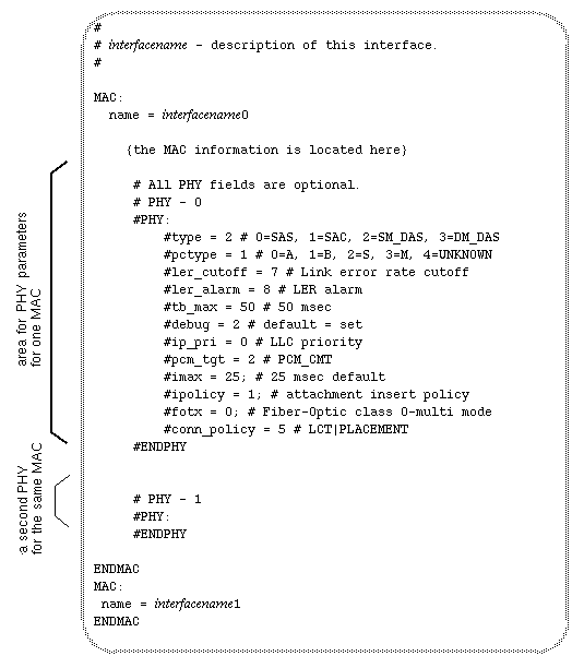
Table C-3. smtd.conf: PHY Parameter Defaults
Parameter | Default Setting | Description |
|---|---|---|
type | read from hardware | Type of device: |
pctype | read from hardware | Port type: |
ler_cutoff | 7 | Link error rate cutoff: |
ler_alarm | 8 | LER alarm: |
tb_max | 50 | Break State timer in msec. |
debug | 2 | 2 = highest debug level. |
ip_pri | 0 | LLC priority. |
pcm_tgt | 2 | PCM_CMT is enabled. |
imax | 25 | Maximum time, in msec, for an Optical bypass switch to insert into ring. |
ipolicy | 1 | Optical bypass switch insertion policy: |
fotx | 0 | Fiber-optic class: |
conn_policy | 5 | PHY connection policy: |
To change one or more of the PHY parameters, follow these steps:
Open the /etc/fddi/smtd.conf file with your favorite editor.
Locate the line containing the PHY parameter you want to alter.
Locate the area labeled with the network interface you want to configure. Be sure to locate the correct type-of-board section (interfacename) as well as the correct specific-interface area (interfacename0, interfacename1, and so on).
The netstat -ina command displays all network interfaces on the station.
Locate the correct PHY area (for example, PHY0 or PHY1) within the MAC area.
Copy the entire line into the area.
Uncomment the line by removing the leftmost pound sign (#). Do not remove the other pound sign (in the center portion of the line) that marks the parameter's description.
Alter the setting of the parameter.
Save the file.
Disable, then enable the network interface, with the commands below:
% su
Password: thepassword
# smtconfig interfacename down
. . .
# smtconfig interfacename up
type |
Type of device.
0=SAS
1=SAC
2=SM_DAS
3=DM_DAS
pctype (fddiPORTMy-Type) |
The entry defines the type of port (PC_TYPE) for this PHY.
0=A
1=B
2=S
3=M
4=unknown
ler_cutoff (fddiPORTLer-Cutoff) |
Link error rate cutoff. Expressed as the cutoff's exponent. For example, 7 means that one error in 107 is allowed before the PHY is removed from ring. The entry is a decimal digit ranging from 4 to 15 inclusive.
ler_alarm (fddiPORTLer-Alarm) |
Link error alarm. Expressed as the exponent of the threshold. For example, 8 means that the alarm occurs after the number of errors exceeds one in 108. The entry is a decimal digit ranging from 4 to 15 inclusive.
tb_max (fddiPORTTB-Max) |
Break state timer for optical bypass switches, set in milliseconds. This entry defines the amount of time that an optical bypass switch will be allowed to continue in a break state before the SMT daemon indicates that the switch is stuck in the break state (sets the BS_Flag) . The entry is a decimal number greater than 30.
debug |
Sets the debugging level, which determines the kinds of error messages displayed by the SMT daemon.
0=low debug level
2=high debug level
ip_pri |
Sets the LLC priority. IRIX does not currently support this functionality. The only valid setting is 0.
pcm_tgt |
Defines the behavior of the physical connection management (PCM). The only valid setting is 2, which enables PCM.
imax (fddiATTACHMENTI-MaxExpiration) |
Maximum time, in milliseconds, for an optical bypass switch to insert into ring. The entry is a decimal number ranging from 0 to 25 inclusive.
ipolicy (fddiATTACHMENTInsertPolicy) |
Sets the insertion policy for the optical bypass switch.
0=insert
1=don't insert
fotx (fddiPORTFotxClass) |
Fiber optic transmitter class. See fiber optic cable in the Glossary.
0=multimode
1=single mode
conn_policy (fddiPORTConnectionPolicies) |
Sets the connection policies (CMT capability flags) supported by this PHY. The entry is a decimal numeral from 0 to 6 inclusive.
Table C-4. CMT Capability Flags
Flag | Description |
|---|---|
0=none | No policy. |
1=LCT | Link confidence testing enabled. |
2=loop | MAC local loop enabled. |
3=LCT and loop | Link confidence and MAC local loop enabled. |
4=placement | MAC is connected to a port (not floating) and is available for link confidence and loop; also referred to as CF_MAC. |
5=LCT and placement |
|
6=Loop and placement |
|
FDDIXPress drivers usually have a few configurable parameters (for example, the size for the maximum transmission unit, MTU). The specific items vary from driver to driver, so they are explained fully within the driver's configuration file.
Driver configuration files reside in the /var/sysgen/master.d directory. Examples of configuration files include if_xpi for the xpi driver and if_ipg for the ipg driver.
After making changes to a configuration file, the operating system (kernel) must be rebuilt to include a driver with the new parameter settings, then the system must be rebooted. The instructions in “Build Configuration Changes Into the System” describe this procedure.