This appendix explains the individual reports that /usr/etc/smtstat -s displays on the screen.
For information on the usage of smtstat, see the smtstat(1M) man page.
The smtstat -s command generates the following reports containing SMT information. Each report is explained in a separate section of this appendix:
In each section, all the fields contained in the report are described. For each field, the following information is described:
Field name as displayed in the report. Fields that correspond to variables in the SMT management information base (MIB) use the MIB variable name.
Possible entries or range of values for that field.
Definition of the field and flags. Some items include the official ANSI name (in parentheses) for the item. For example, (fddiMAC72). More information can be obtained by reading the section on MIB structure in the ANSI SMT document.
The example in Table B-1 defines a field labeled PC withhold from an unnamed report.
Table B-1. smtstat Report Field
Field | Possible Entries | Description |
|---|---|---|
PC withhold |
| The reason for withholding a port connection. (fddiPORT63) |
| NONE | Normal entry. No connection has been withheld. |
| MM | Connection was withheld due to illegal port connection: Port M to Port M. |
| OTHER | Connection was withheld for a nonspecified reason. |
ANSI FDDI documents are the source for much of the text in this appendix. See “Additional Reading” for information about obtaining these documents.
The following user interface allows you to manipulate the reports:
To display a different report, type the report's number. For example, to view the SMT report, type 6.
To quit, press q or Ctrl+C.
To refresh the screen, press Ctrl+L.
To change the time interval for which report statistics are displayed, press one of the following keys:
r Each second, shows totals accumulated since last reboot.
d Resets fields to zero every second, and each second shows totals accumulated within that last second.
z Resets fields to zero when z is pressed, and every second displays the accumulating totals.
The MAC Status report monitors the number of packets transmitted and received and the number of frames and tokens. These numbers are continuously updated on the screen. You can also see the number of address bits (A bits) and copied bits (C bits). These numbers should be almost equal; if they are not, a MAC may have recognized an A bit but was unable to copy it. Figure B-1 shows an example of a MAC Status report.
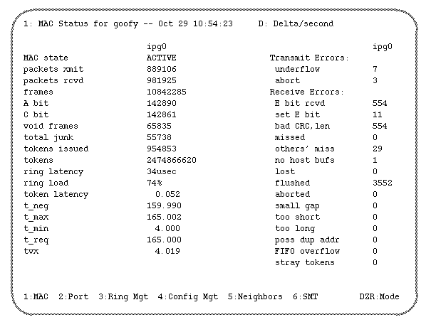
The information on the MAC Status report screen is organized into two columns: the left and the right. Table B-2 explains the left column fields, and Table B-3 describes the right column fields.
Table B-2. MAC Status, Left Column
Field | Possible Entries | Description |
|---|---|---|
MAC state |
| The state of the MAC. |
| ACTIVE | Normal state—transmitting and receiving frames normally. |
| OFF | Hardware off. Normal for initial state. Abnormal once system is configured, rebooted, and SMT daemon is running. |
| CLAIM | In process of sending claim tokens during ring recovery. |
| BEACON | In process of sending beacons after ring recovery failed. |
packets xmit | 0-n | The count of the frames transmitted by this MAC. (fddiMAC73) |
packets rcvd | 0-n | The count of the frames successfully received into this
station's buffers by this MAC. |
frames | 0-n | The number of valid frames that have been seen by this MAC, including those received by this station. This number also includes packets (not addressed to this station and so not received by it) that have passed this MAC on the ring. (fddiMAC71) |
A bit | 0-n | The count of frames received into this station's buffers with the “destination address matched” bit set by a previous station. This bit is set in the frame as it passes a station whose individual address matches the destination address in the frame. |
C bit | 0-n | The count of frames received into this station's buffers with the “frame copied” bit set by a previous station. This bit is set in the frame as it passes a station that copies the frame into the station's buffers. |
void frames | 0-n | The count of discarded frames with the void frame control value transferred into this station's buffers and then discarded. These happen most often when the hardware is in “promiscuous” mode for monitoring by NetLook. Another source is corruption of frames by noise not detected by the frame check sequence (FCS). Such infrequent problems are detected and fixed by higher layer protocols. (NetLook is described in the NetVisualyzer User's Guide.) |
total junk | 0-n | This count includes frames received into a station buffer but discarded because they were void frames, “aborted” (that is, truncated before a proper ending), or “flushed” (that is, the station was too busy to realize that a frame was not meant for it before copying the first part of the frame into a buffer). |
tokens issued | 0-n | The number of tokens sent by this station. The station issues a token after every burst of packets it sends (after grabbing the circulating token) and after winning the claim process when restoring the ring. |
tokens | 0-n | The total number of times this station has seen a token on this MAC. This count is valuable for determining network load. (fddiMAC74) |
token latency | 0-n | The current token rotation time (TRT) in milliseconds. |
ring latency | 0-n usec | The minimum token rotation time in microseconds. |
ring load | 0-n% | The load on the ring, expressed as a percentage. |
t_neg | 0-n | Negotiated target token rotation time (TTRT) in milliseconds obtained during the claim process. (fddiMAC52) |
t_max | 0-n | Maximum TTRT (in milliseconds) supported by this station. (fddiMAC53) |
t_min | 0-n | Minimum TTRT (in milliseconds) supported by this station. (fddiMAC5) |
t_req | 0-n | This station's bid for the TTRT in milliseconds. (fddiMAC51) |
tvx | 0-n | The valid transmission timer (TVX) used for ring recovery. If a valid frame or token is not received within the specified time (in milliseconds), the claim process is started. (fddiMAC54) |
Table B-3. MAC Status, Right Column
Field | Possible Entries | Description |
|---|---|---|
Transmit Errors: |
|
|
underflow | 0-n | The hardware output first-in, first-out buffer underflowed during frame transmission. A large number of these problems indicate a hardware problem. |
abort | 0-n | The line state changed during transmission or the station received a MAC frame (that is, claim or beacon) while the station was transmitting a frame, indicating that the ring is recovering itself. |
Receive Errors: |
|
|
E bit rcvd | 0-n | The number of frames copied into the station's buffers with the frame status error bit already set by a previous station. |
set E bit | 0-n | The count of frames with bad CRC or length that caused this station to set the E bit on a frame passing by this station, including those frames copied into the station's buffers. |
bad CRC, len | 0-n | The count of frames with bad CRC or length copied into station buffers. |
missed | 0-n | Frames this station should have received, but for some reason the station was too busy to copy the frames into a buffer. |
others' miss | 0-n | The count of frames missed by other stations. (This is equal to A bit count minus C bit count.) |
no host bufs | 0-n | This generally counts frames that were received into one set of buffers but discarded because of a lack of buffers at the next stage. |
lost | 0-n | Count of frames dropped by the FORMAC due to, for example, invalid symbols from the PHY. (fddiMAC82) |
flushed | 0-n | Count of flushed frames (that is, the system was too busy to realize that a frame was not meant for it before copying the first part of the frame into a buffer). |
aborted | 0-n | Count of aborted frames (that is, frames truncated before a proper ending). |
small gap | 0-n | Number of times when too small a gap between frames occurred. |
too short | 0-n | Count of frames less than the minimum size. |
too long | 0-n | Count of frames more than the maximum size. |
poss dup | 0-n | Count of frames addressed to this MAC that have the A bit set. Frames directly addressed to this station that already have the A bit set indicate that some other station has the same MAC address as this station. This may count frames with multicast addresses, and so is not a reliable indication of a duplicate address. |
FIFO | 0-n | Hardware input first-in, first-out buffer overflow count. |
stray | 0-n | Count of tokens received while in “Transmit Data” or “Issue Token” states (that is, unexpected tokens). This may indicate a dysfunctional token ring controller somewhere on the ring. |
The Port Status report shows the state of the ports (A and B, or S), including various types of errors, such as a wrap. Highlighted ratio or alarm fields indicate a problem with the port. Figure B-2 is an example of port status information for a DAS.
The Port Status report screen information is organized as two main columns (left and right) and a bottom section. Each column has two subcolumns that list entries for each port (B and A, or S). Table B-4 explains the fields for the left column, Table B-5 describes the right column fields, and Table B-6 describes the bottom section fields.
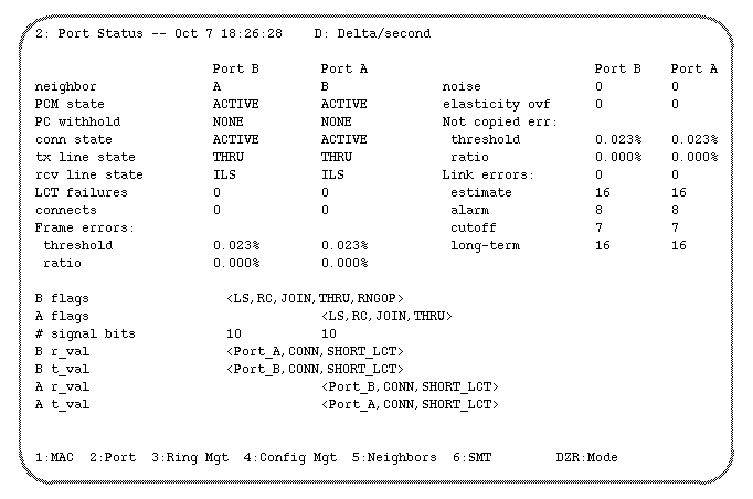
Table B-4. Port Status, Left Column
Field | Possible Entries | Description |
|---|---|---|
neighbor | A, B, M, ? | The type of the port connector (PC) at the other end of the physical connection. This should be watched to detect twisted cables. Port B's neighbor type should be A, and vice versa for a DAS, dual-ring. (fddiPORT13) |
PCM state |
| Current state of the physical connection management (PCM) state machine. (fddiPORT62 )
|
| OFF | Initial state. |
| BREAK | Start of connection. |
| TRACE | Localizing stuck beacon condition. |
| CONNECT | Synchronizing the connection for signaling. |
| NEXT | Signaling state. |
| SIGNAL | Sending/receiving signal bits. |
| JOIN | Initial state for active connection establishment. |
| VERIFY | Verifying state for connection establishment. |
| ACTIVE | Normal entry. Connection established and port is incorporated into ring. |
| MAINT | Maintenance state. |
| BYPASS | Optical bypass switch active or just passing frames or tokens. |
PC withhold |
| The reason for withholding a connection. (fddiPORT63 )
|
| NONE | Normal entry. |
| MM | When an M port is connected to another M port, the connection is withheld. |
| OTHER |
|
conn state |
| Gives a higher-level view of the connect state of the port combining the PCM state and PC withhold values. (fddiPORT61) |
| DISABLED |
|
| CONNECTING | Attempting to connect. |
| STANDBY |
|
| ACTIVE | Normal entry for functioning port. |
tx line state |
| Current transmitted line state. THRU is normal. |
| QLS | Quiet: absence of activity on the medium. |
| HLS | Halt: forced logical break in activity. |
| ILS | Idle: normal condition between transmissions. |
| MLS | Master. |
| ALS | Active. |
| ULS | Unknown (invalid). |
| NLS | Noise. |
| LSU | Cannot determine current state. |
| REP | Repeat, act as a bypass. |
| SIG | Ready to do CMT signaling. |
| THRU | Normal entry. PHY is connected to the ring. |
| WRAP | Ring is wrapped on this port. For a station with two ports where one or both ports are connected to a concentrator, this is normal. |
| LCT | Performing link confidence test. |
| LCTOFF | Link confidence test disabled. |
| BREAK | Break state entered. |
rcv line state |
| Current line state received by this port. ILS is the normal value. |
| QLS | Quiet: used as part of physical connection establishment process. May also indicate absence of a physical connection. |
| HLS | Halt. |
| ILS | Idle: establish and maintain clock synchronization. |
| MLS | Master. |
| ALS | Active: indicates reception of a MAC frame. |
| ULS | Unknown: invalid value. |
| NLS | Noise: indicates noisy physical link. |
| LSU | Cannot determine current state. |
LCT failures | 0-n | Count of total failures of the link confidence test (LCT). The LCT is used to test a link to determine if the link quality is adequate for ring operation. |
connects | 0-n | Count of times since the link was last functional that port has been through the break state without joining. |
Frame errors: |
| Frame errors occur when a frame is lost or is received with errors. |
threshold | 0.023% | The threshold for frame errors. When the ratio exceeds this value, the ratio field becomes highlighted. (fddiMAC95) |
ratio | 0-n% | Ration of current frame errors to total received frames; highlighted when ratio exceeds threshold. (fddiMAC96) |
Table B-5. Port Status, Right Column
Field | Possible Entries | Description |
|---|---|---|
noise | 0-n | Count of times when the line state is bad for a while. The SMT daemon tests the link on which such a “noise event” occurs. |
elasticity ovf | 0-n | Count of elasticity buffer overflows. |
Not copied errors: | 0-n | Not copied errors occur when a bit is seen (that is, the A bit is set) but not copied (that is, the C bit is not set) on a received frame. |
threshold | 0.023% | The threshold for not copied errors. When the ratio exceeds this value, the ratio field becomes highlighted. (fddiMAC103)
|
ratio | 0-n% | Current ratio of not copied errors to total received frames; highlighted when ratio exceeds threshold. (fddiMAC105) |
Link errors: |
| Link error values are average link error rates (LER) that range from a high rate of 4 (indicating 10e–4 or one error in every 10 4 bits) to a low of 16 (indicating 10e–16 or one error in every 1016 bits). This attribute is reported as the absolute value of the base 10 logarithm of the LER estimate value. The LER estimate is expressed as LEM CT/(T*125*10e6). Since T (time duration) is not specified in the SMT standard, the time duration during which the LER is computed is implementation-specific.
|
estimate | 16 | This is the official error rate value advertised in SMT frames for other stations. It is for the link on the indicated port. (fddiPORT51) |
alarm | 8 | The link error rate at which a link connection generates an alarm. This field becomes highlighted when the alarm condition is met. (fddiPORT59) |
cutoff | 7 | The link error rate at which the connection is broken. The SMT daemon shuts down and tests the link when the link error rate becomes more frequent than this level. (fddiPORT58) |
long-term | 4-16 | Long-term link error rate estimate based on all errors seen since the last time the link was reset (that is, the PCM state was BS, for break state). A 4 indicates a high error rate while a 16 indicates a low rate. |
Table B-6. Port Status, Bottom Section
Field | Possible Entries | Description |
|---|---|---|
A, B, and S flags: |
| PCM operational flags (from section 9.4.3.1 of ANSI SMT document). |
| BS | Break state: PCM not leaving break state at appropriate time. |
| LS | A line state has been received since entering current state. |
| RC | Receive code. |
| TC | Transmit code. |
| TD | Transmit delay. |
| JOIN | The port is ready to be incorporated in the token path. |
| HOLD | If dual attach, don't wrap when a fault occurs on a single ring. |
| THRU | The PHY is connected to the ring. |
| DISABLED | Stay in “maint” state. |
| WA | Withhold Port A as a backup link. |
| WAT | Withhold Port A in Tree mode. |
| LEMFAIL | Recently suffered LER cutoff. |
| NE | Noise Event timer expired, indicating that a “noise event” or burst of many 4-bit symbols was corrupted. The link is shut down and retested when a noise event occurs. |
| RNGOP | Ring is operational. |
| OBS | Optical bypass switch present. |
| CON_ | Undesirable physical connection such as |
| C_Illegal | Illegal connection attempted (for example, M-to-M connection). |
| TR_REQ | Trace request. |
| DRAG | Indicates one of the following conditions: taking too long with the link turned off after receiving a TRACE request, or too many consecutive failed attempts to complete PC signaling, including the link confidence test. |
# signal bits |
| The number of PCM signal bits received or transmitted
in the most recent effort to complete PC signaling. If the
most recent PC signaling was successful, then 10 bits
will have been sent and received. |
A and B r_val: |
| Received (set) PCM signal bits. |
| A, B, M, S | Type of port. |
| CONN | Current connection is compatible. |
| CON_ | Current connection is undesirable. |
| short | There is no recent history of excessive link errors. |
| medium,long | A rejection occurred, due to link errors. |
| extended | The port is being withheld from any connection due to an undesirable connection. |
| MAC available for LCT |
|
A and B t_val: | Same as for | Transmitted (set) PCM signal bits. |
The Ring Management Status report shows the status of the ring for an FDDI network interface. An actively growing number of received claims or beacons indicates a problem with the ring, except when a station is being added to the ring. Figure B-3 shows an example of the Ring Management Status report.
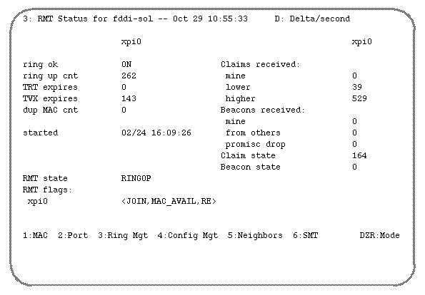
The Ring Management Status report screen information is organized as two columns (left and right) and a bottom section. Table B-7 explains the fields for the left column, Table B-8 describes the right column fields, and Table B-9 describes the bottom section fields.
Table B-7. Ring Management Status, Left Column
Field | Possible Entries | Description |
|---|---|---|
ring ok | ON | Indicates if the ring is in the operational state. This field displays ON while tokens and other frames are circulating. |
ring up cnt | 0-n | Count of times the ring has entered the operational state from the nonoperational state; number of times the token has been lost. (fddiMAC86) |
TRT expires | 0-n | Count of times that the token rotation timer (TRT) expired, indicating that the token was lost which forces ring recovery. See the t_neg and t_req values on MAC Status report. |
TVX expires | 0-n | Count of times that the valid transmission timer (TVX) expired. It can expire when there are no valid frames seen on the ring. It means that the ring must be recovered. See the tvx value on MAC Status report. (fddiMAC83) |
dup MAC cnt | 0-n | Number of indications of possible duplicate MAC address. |
started | date time | The date (month/day) and time (hour:minute:second) when the SMT module started functioning. |
Table B-8. Ring Management Status, Right Column
Field | Possible Entries | Description |
|---|---|---|
Claims received: |
| MAC claim frames containing “requested token rotation timer” (RTRT). Claim frames are used during ring recovery. |
mine | 0-n | Count of station's own claims. |
lower | 0-n | Count of frames with lower values than this station's. The value is either a lower RTRT value, or if the timer value matches this station's, a lower address value. |
higher | 0-n | Count of frames with higher values than this station's. The value is either a higher RTRT value, or if the timer value matches this station's, a higher address value. |
Beacons received: |
| MAC beacon frames are used when there is a serious ring failure, indicating that the claim process failed. |
mine | 0-n | Count of station's own beacons. |
from others | 0-n | Count of other stations' beacons. |
promisc drop | 0-n | Count of beacons received but not copied to host memory (that is, dropped). This can happen when the station is promiscuously receiving (copying into buffers) all frames in order to “snoop” on the fiber while using NetLook. |
Claim state | 0-n | Number of times this station has entered the claim state, when it will transmit MAC claim frames to recover the ring. |
Beacon state | 0-n | Number of times this station has entered the beacon state, when it will transmit MAC beacon frames to recover the ring. |
Table B-9. Ring Management Status, Bottom Section
Field | Possible Entries | Description |
|---|---|---|
RMT state |
| Current state of the Ring Management state machine. (fddiMAC111) |
| ISOLATED | Initial state. |
| NONOP | Ring recovery in progress; ring not operational. |
| RINGOP | Ring is operational. |
| DETECT | Ring not operational for a while. |
| NONOP_DUP | Ring is not operational; this MAC address is likely a duplicate. |
| RINGOP_DUP | Ring operational; however, this MAC address is likely a duplicate. |
| DIRECTED | Stuck beacon (beaconing more than 7 seconds). |
| TRACE | Trace in progress. |
RMT flags: |
| (Section 10.3.1 of ANSI SMT document) |
| JOIN | The port has been incorporated in the token path. |
| MAC_AVAIL | The MAC is available for transmitting and receiving. |
| JM | Jamming has been initialized. |
| NO | The ring has not been operational for an extended period. |
| BN | The MAC is in the beacon state. |
| CLM | The MAC is in the claim state. |
| RE | Recovery enabled. |
The Configuration Information report shows the types of connection paths available and the current paths that pass through the station (the PRiMary and SECondary paths). A CE (Connection Entity) value of INSERT_X indicates that both the primary and secondary paths are used and the ring is wrapped. The report also shows whether an optical bypass switch (OBS) is installed; in this case, an OBS is present. Figure B-4 shows an example of configuration information.
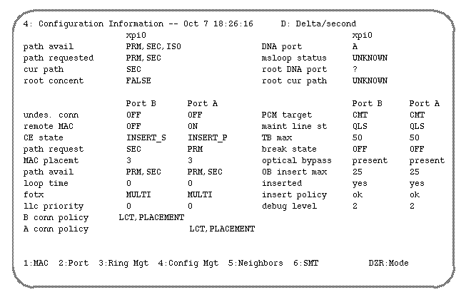
The Configuration Information report screen information is organized as a top section (with two columns), a bottom left column, and a bottom right column. Table B-10 explains the fields for the top section, Table B-11 describes the bottom left column fields, and Table B-12 describes the bottom right column fields.
Table B-10. Configuration Information, Top Section
Field | Possible Entries | Description |
|---|---|---|
path avail |
| Indicates the paths available. |
| PRM | Primary. |
| SEC | Secondary. |
| ISO | Isolated. |
| LOC | Local. |
path requested | same as above | Indicates the path requested. (fddiPATHClass.PATH11) |
cur path | same as above | Indicates the association of the MAC with a
station path. |
root concent | FALSE, TRUE | TRUE indicates a root concentrator MAC. |
DNA port | A, B, M | Downstream neighbor port connection type. |
msloop status | UNKNOWN | Master-slave loop status. |
root DNA port | ?, A, B, M | If a root MAC, indicates downstream neighbor
port type (? means unknown). |
root cur path | UNKNOWN | If a root MAC, indicates the current path. |
Table B-11. Configuration Information, Bottom Left Column
Field | Possible Entries | Description |
|---|---|---|
undes. conn | OFF | Set to ON when an undesirable connection attempt has been made. Indicates that a fiber cable is plugged into the wrong socket. (fddiPORT81) |
remote MAC | OFF | When set to ON, indicates that the remote partner intends to place a MAC in the output token path of this port. (fddiPORT15) |
CE state |
| Current connection entity's (CE) state. (fddiPORT16) |
path request | same as | Indicates the desired path for the port. (fddiPORT17) |
MAC placemt | 0-n | Indicates MAC whose transmit path exits the station through this port. Values start at “total phy count + 1” if there is MAC. (fddiPORT18) |
path avail | same as | Indicates the paths available for the M and S ports. (fddiPORT19) |
loop time | 0-n | Time (in msec) for the optional MAC local loop to prevent deadlock. (fddiPORT21) |
fotx | SINGLE | The fiber optic transmitter (cable) class: single-mode or multi-mode. (fddiPORT22) |
llc priority | 0-n | Link-level control priority. |
B and A, or S |
| The port connection policies on this node. (fddiPORT14) |
| LCT | Link confidence test is performed. |
| LOOP | MAC local loop is made active before connection. |
| PLACEMENT | MAC exists. |
Table B-12. Configuration Information, Bottom Right Column
Field | Possible Entries | Description |
|---|---|---|
PCM target | CMT | Indicates whether CMT is turned on or off. |
maint line st | QLS | Specifies the symbol stream to be transmitted when the PCM is in the maintenance state. See smtmaint(1) reference page. (fddiPORT31) |
TB max | 0-n msec | Break time before the Break State flag is set. (fddiPORT32) |
break state | ON, OFF | When ON, indicates that the PCM state machine is not leaving the break state in an expected time interval and that a problem is suspected. (fddiPORT33) |
optical bypass | none, present | Indicates if an optical bypass switch is present. (fddiATTACHMENT12) |
OB insert max | 0-n | Maximum optical bypass switch insertion/ deinsertion time for this station. (fddiATTACHMENT13) |
inserted | yes, no | Indicates whether the attachment is currently inserted in the node. (fddiATTACHMENT14) |
insert policy | ok | Indicates that it is all right to insert the port. (fddiATTACHMENT15) |
debug level | 0-6 | Current level of debugging/error message logging by the FDDI kernel. |
The Neighbor Information report shows information about a station's upstream and downstream neighbors. It shows whether or not the upstream neighbor address (UNA) and downstream neighbor address (DNA) are valid and if addresses are duplicated. In this case, no duplicate addresses are seen. The report also lists the addresses in FDDI order and canonical order. Figure B-5 shows an example of neighbor information for a station called fddi-sol.
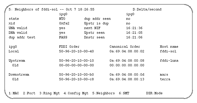
The Neighbor Information report screen information is organized as a top section (with two columns) and a bottom section. Table B-13 explains the fields for the top section, and Table B-14 describes the bottom section fields.
Table B-13. Neighbor Information, Top Section
Field | Possible Entries | Description |
|---|---|---|
state |
| Neighbor notification (NN) transmitter state. |
| NT0 | Wait. |
| NT1 | Send. |
xid | 0-n (in hex) | Current NN transaction ID. |
UNA valid | yes, no | Upstream neighbor address displayed in neighbor ID list (in bottom section) is valid. |
DNA valid | yes, no | Downstream neighbor address displayed in neighbor ID list (in bottom section) is valid. |
dup addr test |
| Current status of duplicate address detection. (fddiMAC29) |
| NONE | Test not performed. |
| PASS | No duplicate address detected. |
| FAIL | Duplicate address detected. |
dup addr seen | yes, no | This MAC has the same address as another MAC on the ring. (fddiMAC112) |
Upstr is dup | yes, no | Upstream neighbor has reported a duplicate address condition. (fddiMAC113) |
next NIF | time | The time (hour, minute, second) when the next Neighbor Information Frame will be sent. |
Upstr seen | time | The time (hour, minute, second) when Neighbor Information Frame (NIF) from upstream neighbor was last seen. |
Dnstr seen | time | The time (hour, minute, second) when Neighbor Information Frame (NIF) from downstream neighbor was last seen. |
Table B-14. Neighbor Information, Bottom Section
Field | Possible Entries | Description |
|---|---|---|
network interface name | ipg#, xpi#, rns# | Identifies the network interface for which information is being displayed. |
| Local | Information about this station. |
| Upstream | Information about the current neighbor immediately upstream. |
| Old | Information about the previous upstream neighbor. |
| Downstream | Information about the current neighbor immediately downstream. |
| Old | Information about the previous downstream neighbor. |
FDDI Order |
| MAC address in FDDI order. |
| 00-00-00-00-00-00 | No station at this location. For Upstream and Downstream, this indicates a wrap. For Old, this is the default when there has not been a change in neighbors. |
| nonzero hex addr | MAC address of a station. |
Canonical Order |
|
|
| 00:00:00:00:00:00 | Same description as for FDDI order. |
| nonzero hex addr | MAC address of a station. |
Host name |
| Network connection name from /etc/ethers file. If ethers file is not available, MAC address is displayed instead of name. |
The SMT Information report displays miscellaneous SMT information not covered in the other reports. It shows the configuration management (CFM) state; if the ring is wrapped, the CFM state field will show WRAP_AB. Figure B-6 displays an example of SMT information.
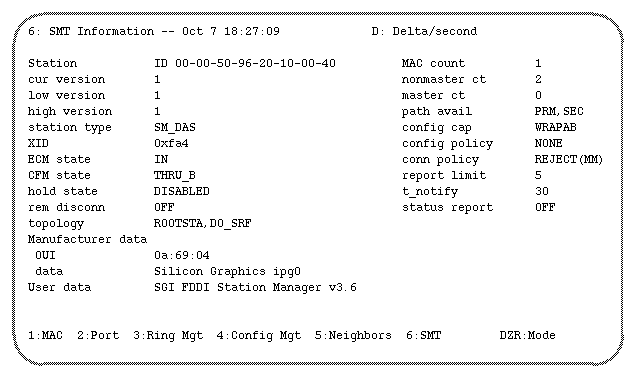
The SMT Information report screen information is divided into left and right columns. Table B-15 explains the fields for the left column, and Table B-16 describes the right column fields.
Table B-15. SMT Information Status, Left Column
Field | Possible Entries | Description |
|---|---|---|
Station ID | 64-bit | Used to uniquely identify an FDDI station. Bottom 48 bits are station's MAC address in FDDI order. (fddiSMT11) |
cur version | 0-n | The version of SMT that is used. (fddiSMT13) |
low version | 0-n hex | The lowest version of SMT that this station supports. (fddiSMT15) |
high version | 0-n hex | The highest version of SMT that this station supports. (fddiSMT14) |
station type |
| Identifies the station type. |
| SAS | Single-attachment station. |
| SAC | Single-attachment concentrator. |
| SM_DAS | Single-MAC, dual-attachment station. |
| DM_DAS | Dual-MAC, dual-attachment station. |
XID | 0-n hex | Current transaction ID. |
ECM state |
| Current entity coordination management (ECM) state. ECM controls the optical bypass switch. (fddiSMT41) |
| IN | Switch is not in bypassed state. |
| OUT | Switch is in bypassed state. |
| TRACE | Indicates stuck beacon condition. |
| LEAVE | Allows time to break connections. |
| INSERT | Allows time for switching. |
| PATHTEST | Testing state. |
| CHECK | State to confirm both switches have switched. |
CFM state |
| Current configuration management (CFM) state. CFM performs the interconnection of PHYs and MACs to configure the ports and MACs within a node. (fddiSMT42) |
| ISOLATED | No connections to PHYs. |
| WRAP_A | Frames can be transmitted on MAC attached to port A. |
| WRAP_B | Frames can be transmitted on MAC attached to port B. |
| WRAP_AB | Displayed for dual-homed DAS only. |
| THRU_A | This MAC is operating on secondary ring. |
| THRU_B | This MAC is operating on primary ring. |
| THRU_AB | Displayed for dual MAC only when it is attached to a concentrator. Both ports are being used. |
hold state | ENABLED | Current state of the hold function. (fddiSMT43) |
rem disconn | ON | Indicates if the station was remotely disconnected from the network. (fddiSMT44) |
topology |
| Flags indicating station topology conditions. (Section 7.3.1.3 of ANSI SMT document)
|
| WRAPPED | Ring is wrapped at this station. For a station with two ports where one or both ports are connected to a concentrator, this is normal. |
| AA_TWIST | A-to-A connection detected. |
| BB_TWIST | B-to-B connection detected. |
| ROOTSTA | Station is on dual ring and not on tree. |
| DO_SRF | Status Report Frames (SRF) reporting is enabled. |
Table B-16. SMT Information Status, Right Column
Field | Possible Entries | Description |
|---|---|---|
MAC count | 0-n | Number of MACs in this station. (fddiSMT21) |
nonmaster ct | 0-n | Number of nonmaster ports (A, B, or S ports) in this station. (fddiSMT22) |
master ct | 0-n | Number of master ports in this node. Nonzero only for concentrators. (fddiSMT23) |
path avail |
| Indicates the path types available in the station. (fddiSMT24) |
config cap |
| Configuration capabilities of the node. (fddiSMT25) |
| HOLDAVAIL | Supports optional hold function. |
| WRAPAB | Wrap state is forced (for example, for attachment to a concentrator). |
config policy |
| Current configuration policies. (fddiSMT26) |
conn policy |
| Current types of connections that are rejected. (fddiSMT27) |
| REJECT(MM) | Reject master-master connections. |
report limit | 0-n | Limit on the number of Status Report Frames (SRFs) to be queued for transmission after the supported condition becomes inactive or after any supported event has been detected. (fddiSMT28) |
t_notify | 0-n seconds | Interval between transmissions of Neighborhood Information Frames (NIFs) by the Neighbor Notification protocol. (fddiSMT29) |
status report | ON, OFF | Indicates whether the node implements the Status
Reporting Protocol. (fddiSMT30) |
Manufacturer data: |
| Manufacturer-defined information. (fddiSMT16) |
OUI | 24-bit value in hex format | Organization unique identification number in canonical format. This value matches the most significant 3 bytes (24 bits) of the MAC address. |
data | string | Text. |
User data |
| User-defined data. (fddiSMT17) |