This chapter discusses the configurations, controls and connectors visible from the front, rear, and inside of the Vault L storage box.
The Vault L (Figure 1-1) is available in two configurations:
a differential storage box
a mixed-channel storage box that supports both single-ended and differential drives
 | Note: You can distinguish between a differential and a mixed-channel Vault L storage box by looking at the back of the chassis. The mixed-channel Vault l has an SE TERM: A (singled-ended) label designator, and the differential Vault L does not. See also Figure 1-3 and Figure 1-4. |
The Vault L storage box supports 8-bit and 16-bit differential SCSI drives and 8-bit single-ended SCSI drives, but does not currently support 16-bit, single-ended drives.
Figure 1-1 shows the front of the Vault L storage box.
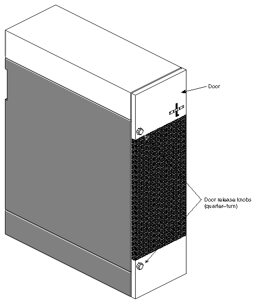
The following major components are visible on the front of the Vault L storage box:
| Drive door | opens and closes using two quarter-turn. Open the drive door by pushing the knob in and turning it counter-clockwise to open. Close the door by pushing the knob in and turning clockwise.
| |||
| On/Off switch | controls power to all drives. This green switch illuminates when turned on. | |||
| Drive shelves | house the SCSI drives and drive sled. The shelves are removable to accommodate full-height drives. See Section 3.2, "Removing a Drive Shelf to Install a Full-Height Drive," in Chapter 3, "Installation," later in this guide.
|
Figure 1-2 shows the front of the Vault L storage box with the drive door open.
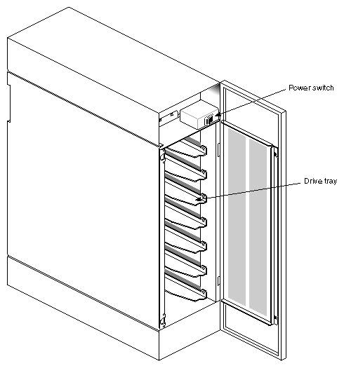
Figure 1-3 shows the back of the differential-only Vault L storage box. Figure 1-4 shows the back of the mixed-channel Vault L.
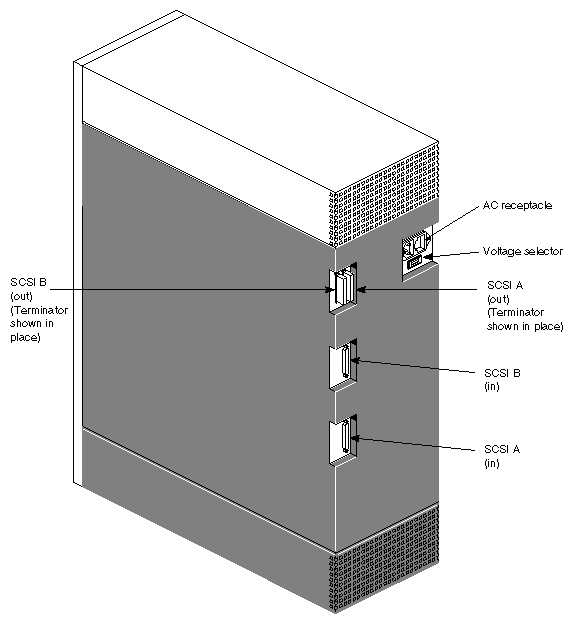
Table 1-1 describes the major components on the back of the differential Vault L storage box. Table 1-2 describes the major components on the back of the mixed-channel Vault L storage box.
Table 1-1. Differential Vault L Rear Panel Connectors and Switches
Rear Panel Connector/Switch | Function |
|---|---|
SCSI In | provides a 68-pin SCSI-2 differential connector |
SCSI Out | provides connection for SCSI termination or a daisy-chain connection to another SCSI device |
Voltage Selector | selects between 115 and 230 VAC |
 | Caution: Ensure that the voltage setting matches the power input source voltage. Damage to the Vault L storage box can result if the setting is incorrect. |
Table 1-2. Mixed-Channel Vault L Rear Panel Connectors and Switches
Rear Panel Connector/Switch | Function |
|---|---|
SCSI In | provides a 68-pin SCSI-2 differential connector |
SE TERM: A | provides single-ended SCSI termination |
DIFF Out: B | provides connection for SCSI termination or a daisy-chain connection to another differential SCSI device |
Voltage Selector | selects between 115 and 230 VAC |
| Caution: Ensure that the voltage setting matches the power input source voltage. Damage to the Vault L storage box can result if the setting is incorrect. |
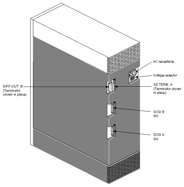
| Note: The mixed-channel Vault L storage box provides connectivity to both single-ended and differential drives. The mixed-channel Vault L has a connector called SE TERM: A; the differential Vault L does have this connector. |
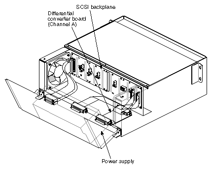
These parts are located inside the Vault L (see Figure 1-5 and Figure 1-6):
| Power supply | provides 5 and 12 volts of power to all drives and fans in the box. | |
| SCSI backplane |
Figure 1-7 shows the front view of the SCSI backplane. Note the pair of green LEDs associated with each drive bay. When illuminated, the top LED signifies that the drive is receiving 5 volts, and the lower LED signifies that the drive is receiving 12 volts. Figure 1-8 shows the rear view of the SCSI backplane and the required jumper settings. | |
| Differential converter board |
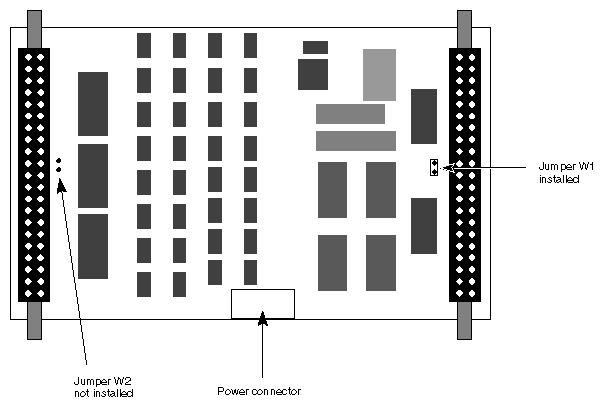
|
| Note: The differential converter board is present only in the mixed-channel Vault L. |
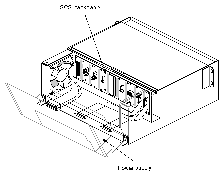
The SCSI backplane enables connection to SCSI devices. Figure 1-7 shows the front view of the SCSI backplane.
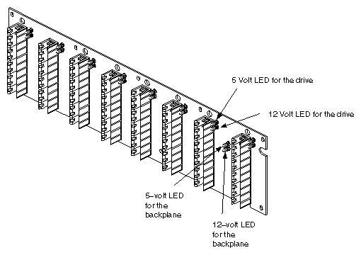
Note the pair of green LEDs associated with each drive bay. When illuminated, the top LED signifies that the drive is receiving 5 volts, and the lower LED signifies that the drive is receiving 12 volts.
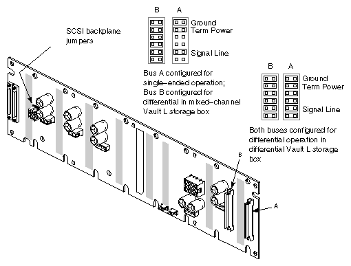
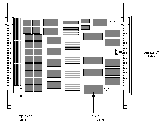
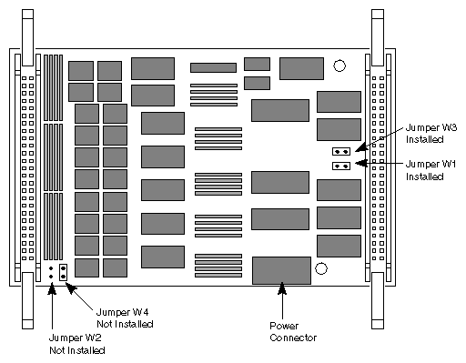
| Caution: Note the different jumper settings for mixed-channel and differential-only SCSI operation. These jumpers must be correctly set for proper drive operation. |
The mixed-channel Vault L storage box can use three versions of the converter board. Two are manufactured by Rancho and the third board is produced by NCR. If you are replacing a converter board in the Vault L, ensure that the replacement board is jumpered according to Figure 1-9 through Figure 1-11.