This chapter covers the following procedures:
installing and removing drives
removing a drive shelf to install a full-height drive
connecting the Vault L storage box to the host system
daisy-chaining Vault L storage boxes
labeling SCSI channels
Perform the following before you actually begin the installation:
Check the number of available differential SCSI ports on the host system. Do you have a sufficient number of channels to support the configuration?
Each Vault L storage box requires at least one dedicated channel, or two channels for disk striping.
Ensure that you are using only differential SCSI channels on the I/O panel.
Check that you have the required cabling. Do you have enough external SCSI cables (P/N 9290053) to handle your configuration? Are you planning to daisy-chain between Vault L storage boxes? If so, do you have enough 2-foot cables (P/N 9290055)?
The Vault L storage box uses front-loading drives mounted on drive sleds for easy installation and removal. Before you install drives into the storage box, you must
select the SCSI ID for the drives
select the correct channel (A or B) on the drive sled
ensure that the drive sled jumpers are set correctly
 | Note: A set of jumpers is also located on the SCSI backplane of the Vault L storage box; however, these jumpers should already be properly set at the factory. |
The drive and drive sled assembly are one modular unit. To install the drive and drive sled assembly in the drive box, follow these steps:
Jumper the SCSI ID for each drive to avoid addressing conflicts. For complete drive jumpering information, refer to the Peripherals Guide.
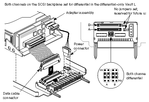
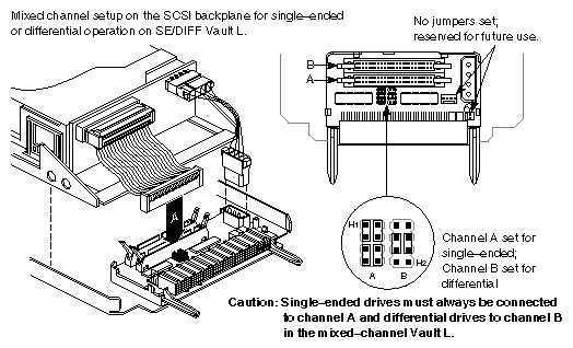
Determine which channel (A or B) you want the drive to occupy, then plug the SCSI cable from the drive into the proper channel connector (see Figure 3-1 or Figure 3-2.)
Set the drive sled for either a single-ended or differential interface. Figure 3-1 and Figure 3-2 show jumper configurations. Ensure the sled is jumpered accordingly for proper drive operation.

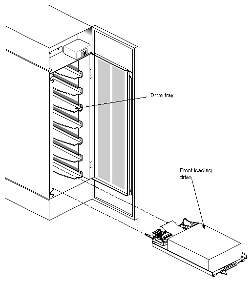
Caution: Channel A on the mixed-channel Vault L must be always be set up for single-ended operation and channel B must always be set up for differential operation. To install a drive, orient the front-loading drive relative to the Vault L so that the drive is facing up (see Figure 3-3).
| Caution: Always install drives beginning from the bottom drive bay to prevent the Vault L storage box from tipping over. |
Install the drive module into the drive shelf and slide the module all the way into place, then push the drive lever all the way to the right. The drive module should click into place, flush with the slot, and should not come out when you pull it.
Close and screw in (one quarter-turn) the Vault L door after you install all of the drives.
Caution: The front door must be closed during operation to comply with FCC regulations. To remove the drive, push the drive lever to the left and then slide the module out as shown in Figure 3-3.
| Caution: Always load drives starting from the bottom drive bay to avoid tipping the Vault L storage box over. |
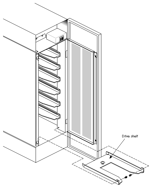
Each full-height drive requires two half-height drive slots. To accommodate the greater size of the full-height drive, remove a drive shelf from the Vault L storage box. Follow these instructions:
Open the front door of the Vault L storage box.
Select a drive shelf; remove the two Phillips screws (No. 0 or 1) that secure the drive shelf at the sides of the Vault L chassis, as shown in Figure 3-4.
Pull the drive shelf out of the chassis and store it for later possible use.
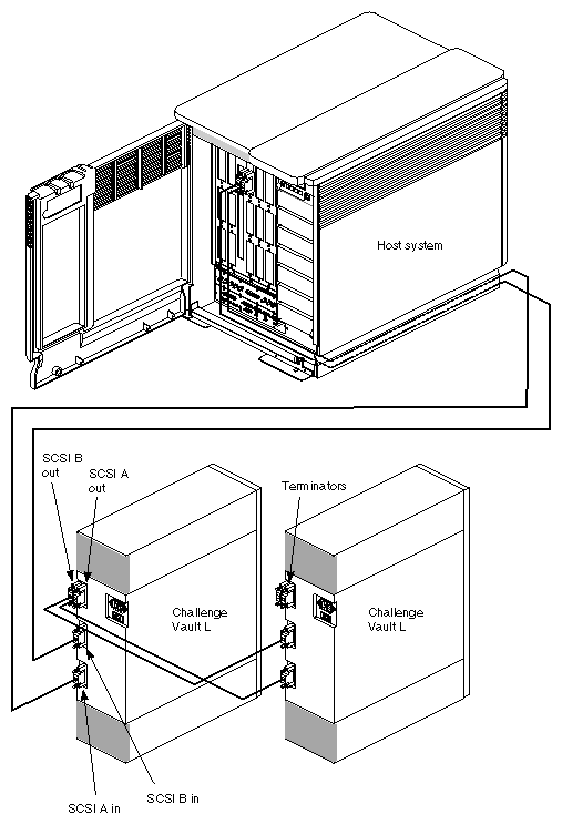
This section explains connecting the SCSI cables from the Vault L storage box to the host system
| Caution: Make sure that the system power is turned off before beginning these steps. |
The Vault L storage box has two SCSI channels (A and B) to help provide disk striping throughput capability. Select an A or B channel for each drive in the storage box, as explained in step 2 of Section 3.1, "Installing and Removing Drives," earlier in this chapter.
Facing the rear of the Vault L storage box, find the SCSI A or B connector.
Label the connectors on the SCSI cable (external 68-pin 50-foot cable SCSI cable, P/N 9290053) you're using to connect the Vault L storage box to the host. An extra set of SCSI labels (P/N 024-0640-001) is provided for this purpose.
Attach one end of the external 68-pin 50-foot cable SCSI cable (P/N 9290053) to the A or B connector, as shown in Figure 3-5.
Open the front door of the deskside host system or rear door of the rackmount host system to access the I/O door. Attach the other end of the SCSI cable to a SCSI port on the I/O panel.
Label the SCSI connector for identification.
Note: The Vault L requires a differential SCSI connection. Connect a terminator into the unused SCSI port on the Vault L storage box.
After installation, make sure all drives and SCSI cables are properly labeled. See Section 3.5, "Labeling SCSI Channels," for more information.
| Note: You can daisy-chain up to two Vault L storage boxes. |
Use a 2-foot cable to daisy-chain differential Vault L storage boxes together. You may daisy-chain up to two Vault L storage boxes. Follow these steps:
Plug one end of a 2-foot cable (P/N 9290055) into an A or B channel on one Vault L storage box.
Caution: You can only daisy-chain differential SCSI devices. Do not attempt to daisy-chain from the SE TERM:A (output) on the mixed-channel Vault L. Plug the other end of the cable into the same channel on the other Vault L storage box.
Plug a terminator into each unused A or B channel on the Vault L storage boxes.
| Note: One channel cannot accommodate more than 15 daisy-chained drives. |
This section describes the SCSI channel labels for individuals who need to determine the configuration of a SCSI channel or who need to modify the SCSI labels for a deskside, rackmount, or Vault L.
To simplify SCSI channel identification, I/O panel SCSI connectors, cables, SCSI devices, SCSI boxes, and terminators are labeled. Depending on the component in question, a label might provide
a channel number to identify the I/O board that provides the SCSI signal
a channel protocol to identify whether the channel is single-ended or differential
a bus number to identify the bus—A or B—inside a SCSI box that supplies the SCSI channel
To determine the protocol of a SCSI channel with missing or unreadable labels, check the configuration of one or more components on the channel using the information in the system's installation instructions.
The easiest component to reach is the drive adapter board. Channel adapter boards are color-coded to simplify identification:
single-ended channel adapter boards are green
differential channel adapter boards are red
The next three figures show SCSI labels:
Figure 3-6 shows CHALLENGE Vault L internal SCSI channel components.
Figure 3-7 shows the location of labels on SCSI devices.
Figure 3-8 shows the location of labels on SCSI cables.
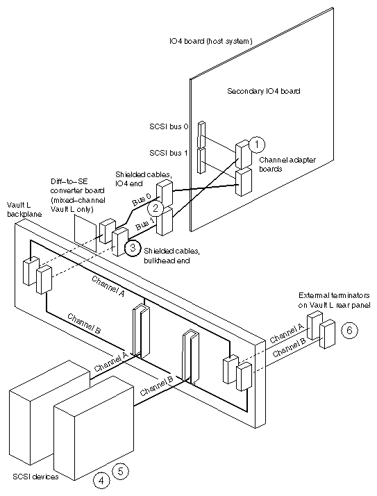
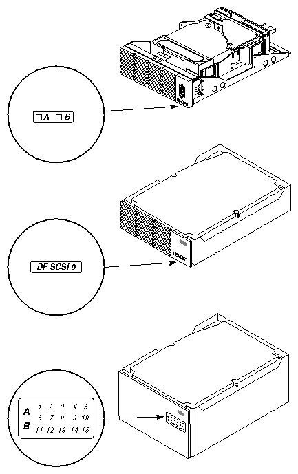
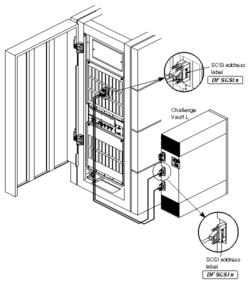
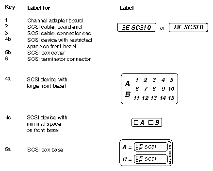
Table 3-1 summarizes the use of SCSI labels. The key numbers in the leftmost column refer to callouts in Figure 3-6 earlier in this chapter
Key | Description | Procedure |
|---|---|---|
1 | Channel adapter board label; identifies SCSI protocol—SE (single-ended) or DF (differential)—and bus number (0-7); SE SCSI 0 label is part number 024-0637-xxx; DF SCSI 1 label is part number 024-0640–xxx; secondary SCSI boxes are labeled from label set part numbers 024–0610–xxx through 024–0654–xxx. | Select label based on the slot and bus number of the IO board. For example, bus 0 on an IO4 board in slot 13 gets the label DF SCSI 130. Place label on the flat face of the cable connector, aligning the bottom of the text along the outer long edge of the connector. |
2 | SCSI cable label, board end; identifies SCSI protocol (SE or DF) and the bus number (0-7); SE SCSI 0 label is part number 024-0637-xxx; DF SCSI 1 label is part number 024-0640–xxx; secondary SCSI boxes are labeled from label set part numbers 024–0610–xxx through 024–0654–xxx. | Select label based on the slot and bus number of the IO board. For example, bus 0 on an IO4 board in slot 13 has the label DF SCSI 130. Place label on the flat face of the cable connector, aligning the bottom of the text along the inner, long edge of the connector. |
3 | SCSI cable label, bulkhead end; identifies SCSI protocol (SE or DF) and the bus number (0-7); SE SCSI 0 label is part number 024-0637-xxx; DF SCSI 1 label is part number 024-0640–xxx; secondary SCSI boxes are labeled from label set part numbers 024–0610–xxx through 024–0654–xxx. | Select label based on the slot and bus number of the IO board. For example, bus 0 on an IO4 board in slot 13 gets the label DF SCSI 130. Place label on the flat face of the cable connector, aligning the bottom of the text along the inner, long edge of the connector. |
4a | SCSI device label for devices with large front bezels; identifies the SCSI channel (A or B), and the device ID number (1-15); part number 024-0632-xxx. | Place label on the inner face of the drive door, along the hinged edge of the door and as close as possible to the corresponding drive. |
4b | SCSI device label for devices with restricted space on the front bezel; identifies the SCSI protocol (SE or DF) and bus number (0-7); SE SCSI 0 label is part number 024-0637-xxx; DF SCSI 1 label is part number 024-0640–xxx; secondary SCSI boxes are labeled from label set part numbers 024–0610–xxx (shown) through 024–0654–xxx. | Select label based on the slot and bus number of the IO board. For example, bus 0 on an IO4 board in slot 13 gets the label DF SCSI 130. Place label on the flat face of the cable connector, aligning the bottom of the text along the inner, long edge of the connector. |
4c | SCSI device label for devices with minimal space on the front bezel; identifies the SCSI channel (A or B); part number 024-0671-xxx. | Place label directly on the face of the drive, ensuring that it does not block any airflow. Indicate whether the device is configured for channel A or B. |
5a | SCSI box base label; part number 024-0655-xxx. | Place label on the inner face of the drive door, in the upper left corner. For each channel, indicate the channel protocol (SE for single-ended, DF for differential) and the SCSI bus number (0 or 1). |
5b | SCSI box cover label; identifies SCSI protocol and bus number (0-7); SE SCSI 0 label is part number 024-0637-xxx; DF SCSI 1 label is part number 024-0640–xxx; secondary SCSI boxes are labeled from label set part numbers 024–0610–xxx (shown) through 024–0654–xxx. | Select label based on the slot and bus number of the IO board. For example, bus 0 on an IO4 board in slot 13 gets the label DF SCSI 130. Place label on the flat face of the cable connector, aligning the bottom of the text along the inner, long edge of the connector. |
6 | SCSI terminator connector label; identifies SCSI protocol (SE or DF) and bus number (0-7); SE SCSI 0 label is part number 024-0637-xxx; DF SCSI 1 label is part number 024-0640–xxx. | Select label based on the slot and bus number of the IO board. For example, bus 0 on an IO4 board in slot 13 gets the label DF SCSI 130. Place label on the flat face of the cable connector, aligning the bottom of the text along the inner, long edge of the connector. |
Figure 3-9 depicts SCSI labels. The key numbers in the leftmost column refer to callouts in Figure 3-6 earlier in this chapter.